EP0818328A1 - Bohrungsverfahren für Speichenrad,Felge gebohrt nach dem Verfahren,Einsatz zur Ausrüstung der Felge und Rad insbesondere für ein Zweirad - Google Patents
Bohrungsverfahren für Speichenrad,Felge gebohrt nach dem Verfahren,Einsatz zur Ausrüstung der Felge und Rad insbesondere für ein Zweirad Download PDFInfo
- Publication number
- EP0818328A1 EP0818328A1 EP97111387A EP97111387A EP0818328A1 EP 0818328 A1 EP0818328 A1 EP 0818328A1 EP 97111387 A EP97111387 A EP 97111387A EP 97111387 A EP97111387 A EP 97111387A EP 0818328 A1 EP0818328 A1 EP 0818328A1
- Authority
- EP
- European Patent Office
- Prior art keywords
- rim
- insert
- bridge
- spoke
- wheel
- Prior art date
- Legal status (The legal status is an assumption and is not a legal conclusion. Google has not performed a legal analysis and makes no representation as to the accuracy of the status listed.)
- Granted
Links
Images


Classifications
-
- B—PERFORMING OPERATIONS; TRANSPORTING
- B60—VEHICLES IN GENERAL
- B60B—VEHICLE WHEELS; CASTORS; AXLES FOR WHEELS OR CASTORS; INCREASING WHEEL ADHESION
- B60B21/00—Rims
- B60B21/06—Rims characterised by means for attaching spokes, i.e. spoke seats
- B60B21/064—Rims characterised by means for attaching spokes, i.e. spoke seats characterised by shape of spoke mounting holes, e.g. elliptical or triangular
-
- B—PERFORMING OPERATIONS; TRANSPORTING
- B60—VEHICLES IN GENERAL
- B60B—VEHICLE WHEELS; CASTORS; AXLES FOR WHEELS OR CASTORS; INCREASING WHEEL ADHESION
- B60B1/00—Spoked wheels; Spokes thereof
- B60B1/02—Wheels with wire or other tension spokes
- B60B1/04—Attaching spokes to rim or hub
- B60B1/041—Attaching spokes to rim or hub of bicycle wheels
-
- B—PERFORMING OPERATIONS; TRANSPORTING
- B60—VEHICLES IN GENERAL
- B60B—VEHICLE WHEELS; CASTORS; AXLES FOR WHEELS OR CASTORS; INCREASING WHEEL ADHESION
- B60B1/00—Spoked wheels; Spokes thereof
- B60B1/02—Wheels with wire or other tension spokes
- B60B1/04—Attaching spokes to rim or hub
- B60B1/043—Attaching spokes to rim
- B60B1/048—Attaching spokes to rim by the use of screws
-
- B—PERFORMING OPERATIONS; TRANSPORTING
- B60—VEHICLES IN GENERAL
- B60B—VEHICLE WHEELS; CASTORS; AXLES FOR WHEELS OR CASTORS; INCREASING WHEEL ADHESION
- B60B21/00—Rims
- B60B21/02—Rims characterised by transverse section
- B60B21/025—Rims characterised by transverse section the transverse section being hollow
-
- B—PERFORMING OPERATIONS; TRANSPORTING
- B60—VEHICLES IN GENERAL
- B60B—VEHICLE WHEELS; CASTORS; AXLES FOR WHEELS OR CASTORS; INCREASING WHEEL ADHESION
- B60B21/00—Rims
- B60B21/06—Rims characterised by means for attaching spokes, i.e. spoke seats
- B60B21/062—Rims characterised by means for attaching spokes, i.e. spoke seats for bicycles
-
- B—PERFORMING OPERATIONS; TRANSPORTING
- B60—VEHICLES IN GENERAL
- B60B—VEHICLE WHEELS; CASTORS; AXLES FOR WHEELS OR CASTORS; INCREASING WHEEL ADHESION
- B60B2900/00—Purpose of invention
- B60B2900/30—Increase in
- B60B2900/311—Rigidity or stiffness
Definitions
- the invention relates to a method for drilling a spoke wheel rim.
- the invention also relates to a rim obtained by the use of the process.
- the invention also relates to a spoke, a spoke nut provided for equip the rim obtained by the process, thus a wheel obtained by the assembly of the rim with such spokes and spoke nuts.
- a wheel in particular a bicycle, comprises a hub central connected by two plies of spokes to a circular rim.
- the rim is formed of two circular bridges connected by two lateral flanks so as to form a box.
- the lateral flanks extend outwards by two wings, so to form with the upper deck an annular channel intended to receive a pneumatic.
- the channel is a simple groove formed by a subsidence of the upper bridge towards the interior.
- the spokes are connected to the rim by nuts screwed to the end of the rays. These nuts also make it possible to adjust the spoke tension.
- the two bridges of the rim are pierced with holes distributed around the circumference of the rim.
- the orifices of the lower deck are intended to serve as a seat for the nut heads.
- the orifices of the upper deck, of larger diameter, are provided to allow the installation spoke nut from the outside.
- eyelets which pass through the holes in the lower deck.
- These eyelets are assembled by crimping to the periphery of the opening of the lower deck. They also have an eyelet body bowl-shaped, the lower part of which rests on the lower deck, and the part upper has a ledge which leans against the upper deck. The bottom of eyelets is drilled for the passage of the nut body.
- a monobloc eyelet is described in patent application EP 130 449. These eyelets also exist in two separate elements assembled at the crimping.
- the holes in the bridges constitute zones local weaknesses which weaken each of the two bridges.
- these orifices must have relatively large dimensions.
- the holes of the lower deck must have a sufficient diameter to allow the passage of the body of the nut, and its free rotation.
- the openings on the upper deck must allow passage of the nut head on which the attachment of the spoke to the rim depends as well as adjustment tools.
- the lower deck which is drilled and tapped must be reinforced by thickness to withstand the stresses resulting in an undesirable increase in weight and inertia of the rim.
- the mounting mode of the shelves does not solve no plus the problem of the twisting of the spokes.
- An object of the invention is to propose a method for drilling a rim which provides a rim with improved mechanical characteristics without significant increase in weight.
- Another object of the invention is to propose a rim pierced with orifices which has improved breaking strength.
- Another object of the invention is to propose a rim whose distance between the two bridges are freed from the height limit constraint of the eyelet cups.
- Another object of the invention is to provide a wheel fitted with spokes, working conditions in traction are improved.
- the method of producing a rim pierced with orifices designed to receive connecting spokes with a hub, the rim having a box with an upper deck and a lower deck is characterized in that at minus the lower deck is pierced with an opening opening by means of a drill discharge drilling operating in the direction of the upper deck.
- the rim obtained by implementing the method is characterized by the fact that at least one of the bridges has a plurality of delimited through orifices by a discharge chimney with a height greater than the thickness of the bridge.
- the radius provided to equip the previous rim is characterized by the fact that it has a tip joined together at the end of the spoke, and a screw of tension adjustment mounted in free rotation recessed with respect to the end piece.
- the wheel according to the invention has a rim as mentioned above, a hub central and connecting spokes between the rim and the hub.
- the rim comprises at least one spoke such that cited above.
- Figure 1 is a general side view of a wheel.
- Figure 2 is a front view of the wheel of Figure 1.
- Figure 3 is a partial front view and in section through a section plane transverse of a rim in the rough.
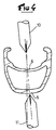
- Figure 4 illustrates the rim drilling operation according to a first mode for implementing the invention.
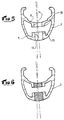
- Figure 5 shows the result of the drilling operation.
- Figure 6 illustrates the next step of tapping the rim holes.
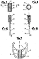
- Figure 7 shows in front view and in section through a transverse plane a insert designed to be screwed into the holes.
- FIG. 8 is a top view and in section of the insert of FIG. 7.
- Figure 9 shows the insert mounted in the rim.
- Figure 10 is a side view of a spoke intended to be assembled to the insert.
- Figure 11 is a view similar to Figure 10 where the elements located the end of the spoke are shown in section.
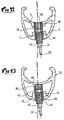
- Figure 12 shows the spoke assembled to the rim.
- Figure 13 is a view similar to Figure 12 and illustrates another mode of implementation of the invention.
- Figure 1 shows a bicycle wheel which includes a rim circular 2 connected to a central hub 3 by spokes 4. Only part of the spokes is shown in this figure.
- the hub has appropriate means to ensure liaison with the framework.
- the rays are distributed in two symmetrical layers, each attached to one end of the hub 3.
- the wheel shown in Figures 1 and 2 is a front wheel.
- one of the plies of spokes is shifted towards the middle part of the hub, so that, on this side, the hub has a tip comprising the freewheel mechanism and serving to support the gearbox gables. This is known to those skilled in the art.
- FIG. 3 shows in cross section and in partial view the rim 2 to raw.
- This rim has in known manner a box structure, with a lower deck 5, an upper deck 6 connected by side walls 7 and 8. These walls extend beyond the upper deck 6 by two wings 9 and 10 which form with bridge 6 an annular channel provided for receiving a tire and a chamber air if applicable.
- the rim shown in the figure is not, however, limiting for the invention, neither as regards the profile of the section, nor as regards the fitting a tire.
- the invention applies in fact as well to the rims provided to be fitted with a tire only rims intended to be fitted with a hose or other tread.
- the rim such as that shown in FIG. 3 is produced at from a profiled bar made of aluminum alloy or another alloy lightweight, which is bent, then assembled end to end by means of a sleeve or by welding. In the raw state, the two bridges are continuous, non-pierced walls.
- Figures 4 and 5 illustrate the drilling operation of the rim.
- This operation consists in known manner of drilling the two bridges of the rim at intervals regular, to allow the hanging of the shelves. It should be noted that the drilling holes takes into account the proper orientation of each radius, this orientation being determined by the general orientation of each layer, and by the number of rays per tablecloth.
- the rims are drilled not using a cutting forest traditional, but through a forest that operates by repression.
- the drilling technique by repression is known in itself.
- Forests used for such drilling have a generally cylindrical shape, with a point in the shape of a punch. The point is shaped with edges, which gives it overall the shape of a pointed pyramid.
- Other forms of tools may also be suitable.
- Two tools 10 and 11 are used in this case to pierce the two bridges. They are mounted coaxially, and are driven in movement from rotation and translation towards the rim by any suitable means.
- the technique of drilling by repression presents the peculiarity of not cut the material, but push it back in the direction of advancement of the forest according to a fireplace.
- the chimneys are oriented towards inside the rim box.
- Push-back drilling can create a burr on the side opposite the fireplace.
- This burr is trimmed or shaped by the drilling tool itself which has at least one deburring tooth for this purpose.
- the burr can also be deburred or shaped by a clean machining operation.
- FIG. 5 represents the rim in cross section at the level of a torque orifices, after drilling and removal of the forests.
- Each bridge 5, 6 has an orifice opening 13, 14 delimited by a chimney 15, 16 which extends towards the interior of the box.
- the two orifices 13 and 14 have the same diameter. This is not limiting, and as will be described later, they may have a different diameter.
- the wall height and its thickness depend on the characteristics of the rim material, the initial thickness of the bridge, the diameter of the forest, and drilling parameters, rotation speed, forward speed, etc.
- the drilling of the orifices by the backflow technique is advantageous in terms of the mechanical strength of the rim.
- the structure of matter no longer exhibits abrupt discontinuity as in the traditional drilling by cutting. Thanks to its peripheral wall, the chimney maintains a certain homogeneity in the structure of the bridges, so that the mechanical resistance to rupture of the rim thus pierced is higher than that of a rim pierced in the traditional way.
- Another advantage is that such discharge drilling does not generate chip, and in particular there is no chip that could break into inside the box.
- FIG. 6 illustrates the next manufacturing step which consists in tapping the two ports 13 and 14 of the bridges. After tapping, it is planned to screw in the two orifices a monobloc insert, so that the two threads are made one depending on the other. If the two holes have the same diameter, we can make the two tapping operations with a single tap in a single pass. If the holes do not have the same diameter, you can use a multi-stage tap, or all other appropriate means.
- the insert 18 intended to be screwed into the two tapped holes is shown in Figures 7 and 8. It is in the form of a portion of tube which is threaded on its outer wall to the diameter and pitch of the orifices 13 and 14. From preferably the length of the insert is equal to or slightly less than the distance between the upper surface of the upper deck 6 and the lower surface of the bridge lower 5, so that once screwed into the two holes of the bridges, the insert is fully integrated inside the perimeter of a rim section.
- the inside of the insert is also tapped with a pitch which is independent of the not external of the insert.
- the interior of the insert has at least in its lower part a polygonal section, for example hexagonal, which is made in the thickness of the thread.
- this hexagonal section allows you to screw the insert into holes 13 and 14 using, for example, a wrench appropriate hexagonal.
- the hexagonal shape serves also anti-rotation guide with a tip located at the end of the spoke.
- Other means may also be suitable for coupling with a tool for screwing the insert, for example one or more grooves made on the internal wall of the insert over all or part of its height, and designed to cooperate with a tool carrying one or more lugs arranged so appropriate.
- the insert could present on the side of the lower deck, i.e. towards the inside of the rim, a projecting extension, with an outer section for example hexagonal which allows the coupling of a screwing tool. This replaces the hexagonal section inside the insert.
- This hexagonal section internal is preferred, however, because it allows weight gain on the inserts, space saving also, and it facilitates the placement of the shelves which will described in more detail later.
- the insert is made of any suitable material, for example alloy aluminum.
- the insert is designed to be screwed into the holes 13 and 14 of the rim, and, from preferably immobilized, by any suitable means, for example by bonding.
- the FIG. 9 illustrates this step of producing the rim equipped with the inserts.
- the insert 18 makes a mechanical connection between the two bridges 5 and 6, which operates in both directions in a longitudinal direction defined by the insert. That is to say that unlike the eyelets which are set on one of the bridges and by simple support on the other, the inserts are here embedded in each of the bridges and they connect the bridges together. The risk of the housing collapsing is considerably reduced.
- the rim structure is stiffened by such connections. It was already stiffened by the discharge chimneys.
- discharge drilling allows a height at each bridge which is much greater than the initial thickness of the wall of the bridge. In other words, we can here implement a screw connection without significantly increase the wall thickness.
- the length of the insert is not limited by manufacturing constraints, so that the distance which separates the two bridges from the rim is chosen without constraint relating to the length of the insert.
- the shape of the lower deck can also be chosen for example more streamlined, because the insert is no longer crimped but screwed inside the rim.
- a spoke intended to be attached to the rim by screwing into the insert is shown in Figures 10 and 11.
- the spoke 25 which is represented is a metal wire with a bent head 26 which is designed to be attached to a lateral flange of a hub, by threading in one of the holes in the flange.
- This is of course not limiting, and the radius could also be straight head, i.e. without elbow, and be assembled by any technique other than threading, for example by simple engagement of the head in a slot in the form of a buttonhole or in a notch.
- the section of the median part of the radius is arbitrary, in particular it can be cylindrical or present an aerodynamic profile.
- the spokes could also be replaced by sticks assembled to the hub or integral therewith, the spoke part which will now be described constituting the end part of such sticks.
- the spokes could also be formed from composite fibers.
- This end portion includes a tip 28 which is secured to the end of the spoke by any appropriate means, for example by screwing and gluing on the threaded end of the spoke.
- the tip could also be assembled by welding, by matting the end of the spoke, or it could be achieved by stamping of the very end of the spoke. According to the method of assembly of the head radius to the hub, in particular by threading or by engagement in a slot, the tip is assembled after or before the spoke placement operation on the hub.
- the end piece 28 has a polygonal section, for example hexagonal which corresponds to the internal section of the insert.
- the tip is provided to be engaged and slide inside the insert 18.
- the fact that the insert has a hexagonal internal section facilitates the positioning of the spoke, even before its Tightening.
- the end of the spoke carries a screw for adjusting tension 30 which is crossed by the spoke, and mounted in free rotation at its end.
- the screw is intended to abut against the end piece 28 and exert on it a thrust inducing by reaction a tension in the radius.
- the screw 30 is also designed to be screwed inside the insert 18, thereby inducing a translation of the nozzle 28 inside the insert.
- the screw tension adjustment is extended on the side opposite the end piece by a sleeve coupling with a tightening tool, for example a section sleeve 31 hexagonal. Any other suitable means is also suitable.
- Figure 12 shows schematically the rim in a section plane including the insert.
- This figure represents the various elements, in particular the insert 18 engaged in the two orifices of the bridges 5 and 6 of the rim, the end piece 28 engaged at sliding in the insert, and the tension adjustment screw 30 partially screwed into the insert, with the coupling sleeve 31 accessible outside the rim which adjusts the spoke tension. It should be noted that when adjusting the tension, the spoke only works at stretching since the end piece 28 prevents the end of the spoke from pivoting. The rays work in better This makes the tension setting more precise.
- the construction which has just been described is capable of being carried out with many variations.
- a forest that performs in the same operation the tapping of one at least holes.
- self-tapping inserts that's say that create their own thread when screwing them.
- Another variant would consist of tapping only one orifice, for example the orifice of the lower deck, and ensuring the connection with the other bridge by a self-tapping section of the insert.
- the two orifices could be drilled by a single forest oriented operating on the upper deck then on the lower deck. Such drilling would have to orient the chimney of the lower deck towards the outside of the box.
- the two orifices could have different diameters, the insert in this case having a shoulder on which it can be supported to ensure its tightening in the holes.
- Figure 13 shows another mode of implementation of the invention.
- only the lower bridge 35 of the rim 32 is drilled using the discharge technique, so as to create a chimney 37.
- the upper bridge 36 is not pierced, it remains in the raw state.
- an insert 38 is engaged by screwing in the chimney 37, and tightened against the upper deck. Insert 38 looks like previous insert 18, with an internal wall threaded and machined in a hexagonal section.
- the radius 39 intended to cooperate with the insert 38 is entirely similar to the previous spoke, with a tip 40 of hexagonal section at its end, a tension adjustment screw 41 extended by a coupling sleeve with a clamping tool.
- Such a construction has the advantage that the rim is waterproof, it is say that on the side of the tire, it has a continuous bridge, not drilled except in the case if necessary for mounting the valve.
- a rim is suitable for a tubeless tire fitting, or a fitting where only part of the volume defined by the tire is occupied by an inner tube or a material of filling, the other part being occupied by pressurized air injected between the rim and tire.
- This other embodiment of the invention is also susceptible variants of the same nature as that which have been previously described.
Priority Applications (1)
| Application Number | Priority Date | Filing Date | Title |
|---|---|---|---|
| EP05003972A EP1531062B1 (de) | 1996-07-12 | 1997-07-05 | Bohrungsverfahren für Speichenrad, Felge gebohrt nach dem Verfahren, Einsatz zur Ausrüstung der Felge und Rad insbesondere für ein Zweirad |
Applications Claiming Priority (2)
| Application Number | Priority Date | Filing Date | Title |
|---|---|---|---|
| FR9609047A FR2750913B1 (fr) | 1996-07-12 | 1996-07-12 | Procede de percage d'une jante a rayon, jante percee selon le procede, insert adapte pour equiper la jante, et roue notamment de cycle |
| FR9609047 | 1996-07-12 |
Related Child Applications (1)
| Application Number | Title | Priority Date | Filing Date |
|---|---|---|---|
| EP05003972A Division EP1531062B1 (de) | 1996-07-12 | 1997-07-05 | Bohrungsverfahren für Speichenrad, Felge gebohrt nach dem Verfahren, Einsatz zur Ausrüstung der Felge und Rad insbesondere für ein Zweirad |
Publications (2)
| Publication Number | Publication Date |
|---|---|
| EP0818328A1 true EP0818328A1 (de) | 1998-01-14 |
| EP0818328B1 EP0818328B1 (de) | 2006-08-30 |
Family
ID=9494219
Family Applications (2)
| Application Number | Title | Priority Date | Filing Date |
|---|---|---|---|
| EP97111387A Expired - Lifetime EP0818328B1 (de) | 1996-07-12 | 1997-07-05 | Bohrungsverfahren für Speichenrad,Felge gebohrt nach dem Verfahren,Einsatz zur Ausrüstung der Felge und Rad insbesondere für ein Zweirad |
| EP05003972A Expired - Lifetime EP1531062B1 (de) | 1996-07-12 | 1997-07-05 | Bohrungsverfahren für Speichenrad, Felge gebohrt nach dem Verfahren, Einsatz zur Ausrüstung der Felge und Rad insbesondere für ein Zweirad |
Family Applications After (1)
| Application Number | Title | Priority Date | Filing Date |
|---|---|---|---|
| EP05003972A Expired - Lifetime EP1531062B1 (de) | 1996-07-12 | 1997-07-05 | Bohrungsverfahren für Speichenrad, Felge gebohrt nach dem Verfahren, Einsatz zur Ausrüstung der Felge und Rad insbesondere für ein Zweirad |
Country Status (4)
| Country | Link |
|---|---|
| US (2) | US6224165B1 (de) |
| EP (2) | EP0818328B1 (de) |
| DE (2) | DE69738093T2 (de) |
| FR (1) | FR2750913B1 (de) |
Cited By (8)
| Publication number | Priority date | Publication date | Assignee | Title |
|---|---|---|---|---|
| FR2793444A1 (fr) * | 1999-05-12 | 2000-11-17 | Mavic Sa | Dispositif d'accrochage d'un rayon a la jante d'une roue de bicyclette |
| EP1084868A1 (de) * | 1999-09-17 | 2001-03-21 | Mavic S.A. | Fahrradfelge und Rad mit solcher Felge |
| EP1101631A1 (de) * | 1999-11-18 | 2001-05-23 | Mavic S.A. | Befestigungsvorrichtung für das Ende einer Speiche an einer Felge oder Nabe |
| FR2810582A1 (fr) | 2000-06-27 | 2001-12-28 | Mavic Sa | Dispositif d'accrochage d'un rayon a la jante d'une roue de bicyclette |
| EP1688272A2 (de) | 2005-02-08 | 2006-08-09 | Salomon S.A. | Radfelge und Herstellungsverfahren |
| FR2900869A1 (fr) | 2006-05-12 | 2007-11-16 | Salomon Sa | Roue a rayons |
| US8733846B2 (en) | 2006-08-25 | 2014-05-27 | Mavic Sas | Spoke for a spoked wheel, method of manufacture thereof, and wheel including such spoke |
| CN104889232A (zh) * | 2015-04-24 | 2015-09-09 | 浙江金固股份有限公司 | 一种钢制车轮轮辐螺母座孔制作方法 |
Families Citing this family (47)
| Publication number | Priority date | Publication date | Assignee | Title |
|---|---|---|---|---|
| IT1320582B1 (it) * | 2000-08-03 | 2003-12-10 | Campagnolo Srl | Cerchio per una ruota di bicicletta con pneumatico senza camera d'aria. |
| US6347839B1 (en) * | 2000-09-25 | 2002-02-19 | Polymeric Corporation The | Composite rim |
| US6568766B1 (en) * | 2001-02-28 | 2003-05-27 | Shimano Inc. | Bicycle rim |
| TW514031U (en) * | 2002-04-30 | 2002-12-11 | Jen-Ping Tian | Improved fabricating structure for spokes of wheel rim on a bicycle |
| DE10227574A1 (de) * | 2002-06-20 | 2004-01-08 | Dt Swiss Ag | Verfahren zur Herstellung einer Felge und Felge, insbesondere für ein Fahrrad |
| US20040066085A1 (en) * | 2002-10-05 | 2004-04-08 | Jason Schiers | One-piece composite rim |
| DE60225814T2 (de) * | 2002-11-08 | 2009-04-30 | Campagnolo S.R.L. | Verfahren zur Herstellung eines Speichenrads für Fahrräder |
| US6736462B1 (en) * | 2002-12-16 | 2004-05-18 | Shimano, Inc. | Bicycle rim |
| US6811228B2 (en) * | 2002-12-31 | 2004-11-02 | Tseng Ping Tien | Wheel having spoke solidly coupling device |
| US7192098B2 (en) * | 2003-05-07 | 2007-03-20 | Shimano Inc. | Bicycle rim |
| ES2305430T3 (es) * | 2003-06-26 | 2008-11-01 | Campagnolo S.R.L. | Llanta aligerada para una rueda de bicicleta y procedimiento de fabricacion de dicha llanta. |
| US20050023883A1 (en) * | 2003-08-01 | 2005-02-03 | Shimano Inc. | Bicycle rim |
| EP1506882B1 (de) * | 2003-08-11 | 2008-07-09 | Campagnolo Srl | Fahrradfelge aus Verbundwerkstoff und Verfahren zu ihrer Herstellung |
| BRPI0417787A (pt) * | 2003-12-18 | 2007-03-20 | Alpina Raggi Spa | roda raiada para pneus |
| DE602004012703D1 (de) * | 2004-01-27 | 2008-05-08 | Campagnolo Srl | Befestigungssystem für Speichen in einem Fahrradrad |
| JP2005319962A (ja) * | 2004-05-11 | 2005-11-17 | Shimano Inc | 自転車用リム |
| JP4394522B2 (ja) * | 2004-06-08 | 2010-01-06 | 本田技研工業株式会社 | チューブレスタイヤ用ホイール |
| PT1629997E (pt) * | 2004-08-31 | 2008-03-24 | Campagnolo Srl | Aro para uma roda com raios de bicicleta, a roda e processo de fabrico |
| US7427112B2 (en) * | 2004-12-28 | 2008-09-23 | Raphael Schlanger | Rim for a spoked wheel |
| US7490406B2 (en) * | 2005-05-04 | 2009-02-17 | William Shook | Bicycle wheel rim with internally reinforced spoke seats and method for producing them |
| FR2890896B1 (fr) | 2005-09-16 | 2007-10-26 | Salomon Sa | Procede de fabrication d'une roue a rayons en tension et roue a rayons en tension |
| US20070278848A1 (en) * | 2006-06-06 | 2007-12-06 | Alex Global Technology, Inc. | Wheel rim |
| US7631945B2 (en) * | 2007-08-28 | 2009-12-15 | Trek Bicycle Corporation | Bicycle wheel with over-sized spokes |
| US7726746B2 (en) * | 2007-08-28 | 2010-06-01 | Berens Martin C | Hubcap having lighted spinning element |
| ITMI20072232A1 (it) * | 2007-11-26 | 2009-05-27 | Campagnolo Srl | Cerchio per ruota di bicicletta e ruota di bicicletta comprendente tale cerchio |
| ITMI20072231A1 (it) * | 2007-11-26 | 2009-05-27 | Campagnolo Srl | Cerchio per ruota di bicicletta e ruota di bicicletta comprendente tale cerchio |
| ATE509779T1 (de) * | 2008-03-14 | 2011-06-15 | Campagnolo Srl | Radfelge aus verbundmaterial für ein schlauchloses fahrradrad und ein mit einer solchen radfelge ausgestattetes schlauchloses fahrradrad |
| US20100264722A1 (en) * | 2009-04-17 | 2010-10-21 | Teixeira Iv Charles R | Bicycle rim with mechanical spoke attachment |
| US20120013171A1 (en) * | 2010-07-17 | 2012-01-19 | Wen Hsuan Chen | Spoke Nipple with an Anti-shock Structure and its Manufacturing Method |
| TW201204574A (en) * | 2010-07-22 | 2012-02-01 | jing-shan Wang | Bicycle wheel rim |
| TW201208904A (en) * | 2010-08-24 | 2012-03-01 | jing-shan Wang | Bicycle wheel |
| US8449044B2 (en) | 2010-09-27 | 2013-05-28 | Shimano Components (Malaysia) Sdn. Bhd. | Bicycle rim |
| FR2965753B1 (fr) | 2010-10-12 | 2012-11-16 | Mavic Sas | Roue pour cycle et methode d'assemblage d'une telle roue |
| US8746808B2 (en) * | 2011-02-14 | 2014-06-10 | Shimano Components (Malaysia) Sdn. Bhd. | Bicycle rim |
| TWM415823U (en) * | 2011-03-16 | 2011-11-11 | Kunshan Henry Metal Tech Co | Spoke tightening lock structure |
| US8985708B2 (en) | 2012-06-04 | 2015-03-24 | Spinergy Inc. | Wheel with high strength flexible spokes |
| US9636943B2 (en) | 2012-06-04 | 2017-05-02 | Spinergy Inc. | Wheel with high strength flexible spokes |
| US9682596B2 (en) | 2012-06-04 | 2017-06-20 | Spinergy Inc. | Wheel with high strength flexible spokes |
| US8985707B1 (en) | 2012-06-04 | 2015-03-24 | Spinergy Inc. | Wheel with flexible wide-body spokes |
| ITMI20130201A1 (it) * | 2013-02-13 | 2014-08-14 | Campagnolo Srl | Cerchio di ruota di bicicletta e relativa ruota di bicicletta |
| USD798791S1 (en) | 2016-01-06 | 2017-10-03 | Spinergy Inc. | Spoke |
| JP2017178215A (ja) * | 2016-03-31 | 2017-10-05 | 本田技研工業株式会社 | チューブレススポークホイールの構造 |
| TWI615290B (zh) * | 2016-08-30 | 2018-02-21 | 亞獵士科技股份有限公司 | 碳纖維輪圈強化結構 |
| TWI626174B (zh) * | 2017-06-12 | 2018-06-11 | Wheel rim for bicycle and method for processing spoke hole of the rim | |
| TWI623447B (zh) * | 2017-06-12 | 2018-05-11 | Wheel rim for bicycle and method for processing nozzle hole of the rim | |
| US11701918B1 (en) | 2019-04-17 | 2023-07-18 | Hed Cycling Products, Inc. | Bicycle rim adapted to reduce spoke fatigue |
| US11396206B2 (en) * | 2020-01-05 | 2022-07-26 | Sheng 1 First Co., Ltd. | Bicycle wheel |
Citations (6)
| Publication number | Priority date | Publication date | Assignee | Title |
|---|---|---|---|---|
| US2937905A (en) * | 1955-11-29 | 1960-05-24 | Altenburger Karl | Spoke connection for tubeless tire rim |
| EP0130449A2 (de) * | 1983-06-24 | 1985-01-09 | Campagnolo S.p.A. | Schräge Buchsen für Fahrradfelgen und Felgen die damit ausgestattet sind |
| JPS6181801A (ja) * | 1984-08-31 | 1986-04-25 | Honda Motor Co Ltd | 車輌用ワイヤスポ−ク・ホイ−ルの組立て方法 |
| DE4143380A1 (de) * | 1991-11-15 | 1993-05-19 | Continental Ag | Speichenrad und felge dafuer, sowie felgenherstellungsverfahren |
| WO1993009963A1 (de) * | 1991-11-15 | 1993-05-27 | Klaus Kleinhoff | Speichenrad, felge und nippel für speichenrad und verfahren zur herstellung von felgen für ein speichenrad |
| WO1996011075A1 (en) * | 1994-10-05 | 1996-04-18 | Holland Mechanics B.V. | Method and apparatus for making nipple holes in a double-walled hollow rim of a spoke wheel |
Family Cites Families (36)
| Publication number | Priority date | Publication date | Assignee | Title |
|---|---|---|---|---|
| US183647A (en) * | 1876-10-24 | Improvement in carriage-wheel fellies | ||
| US399453A (en) * | 1889-03-12 | Vehicle-wheel | ||
| US1316605A (en) * | 1919-09-23 | Wheel with | ||
| US804617A (en) * | 1905-06-19 | 1905-11-14 | Nelson A Newton | Vehicle-wheel. |
| US1286065A (en) * | 1918-05-09 | 1918-11-26 | Thomas E Murray | Device for attaching the ends of wire wheel-spokes to metal rims. |
| US1676303A (en) * | 1919-02-24 | 1928-07-10 | James H Wagenhorst | Vehicle wheel |
| US1367092A (en) * | 1919-02-24 | 1921-02-01 | George S Porter | Method of making wheels |
| US1584576A (en) * | 1919-02-24 | 1926-05-11 | James H Wagenhorst | Vehicle wheel |
| US1469769A (en) * | 1919-04-23 | 1923-10-09 | William N Booth | Metallic felly and rim for vehicle wheels |
| US1451911A (en) * | 1922-10-30 | 1923-04-17 | Johnson Nels | Bicycle rim |
| US1649678A (en) * | 1927-01-07 | 1927-11-15 | Richard A Jackson | Tire rim |
| US1906953A (en) | 1929-02-20 | 1933-05-02 | Winford L Enghauser | Method of forming manifolds |
| GB416249A (en) * | 1933-01-26 | 1934-09-13 | Mario Longhi | Improvements in and relating to rims or felloes for the wheels of bicycles and similar vehicles |
| FR1029764A (fr) * | 1950-12-16 | 1953-06-05 | Perfectionnements aux jantes pour cycles et autres | |
| US3008770A (en) | 1956-12-19 | 1961-11-14 | American Mach & Foundry | Rim for tubeless bicycle tires |
| FR1189384A (fr) | 1957-12-31 | 1959-10-02 | Houilleres Bassin Du Nord | Procédé et outil de formation de collets, et collets résultant de ce procédé |
| NL160499B (nl) | 1974-11-28 | 1979-06-15 | Geffen Tech Adviesbureau Bv | Doorn voor het maken van een door een kraag omgeven gat in een metalen plaat of wand van een metalen buis. |
| NL7700871A (nl) | 1977-01-27 | 1978-07-31 | Geffen Tech Adviesbureau Bv | Werkwijze en inrichting voor het door wrij- vingswarmte en druk maken van een door een kraag omgeven gat in metalen plaat of de wand van een metalen buis. |
| NL7712700A (nl) | 1977-11-17 | 1979-05-21 | Geffen Tech Adviesbureau Bv | Draaibare doorn voor het maken van kraaggaten. |
| US4428214A (en) | 1982-02-08 | 1984-01-31 | Deere & Company | Flow drilling process and tool therefor |
| EP0150518B1 (de) | 1984-01-30 | 1988-05-04 | Flowdrill B.V. | Fliessbohrwerkzeug, insbesondere zur Verwendung in einer Handbohrmaschine |
| JPS62275801A (ja) * | 1985-11-18 | 1987-11-30 | Toray Ind Inc | 車輪用リムおよびその製造方法 |
| US5110190A (en) | 1990-03-16 | 1992-05-05 | Johnson Harold M | High modulus multifilament spokes and method |
| FR2693672B1 (fr) | 1992-07-15 | 1994-11-04 | Mavic | Procédé de fabrication d'une jante pour cycle et jante réalisée avec ce procédé. |
| DE4224131A1 (de) | 1992-07-22 | 1994-01-27 | Stabilus Gmbh | Verfahren zur Herstellung eines Anschlußstutzens |
| US5499864A (en) * | 1993-06-16 | 1996-03-19 | Klein Bicycle Corporation | Bicycle wheel rims |
| FR2707559B1 (fr) | 1993-07-02 | 1995-09-29 | Bg Innovation | Perfectionnement pour roue destinée à équiper les cycles. |
| FR2722735B1 (fr) | 1994-07-25 | 1996-10-04 | Bg Innovation | 1roue pour cycle dont les rayons son2l'intermediaire d'une piece indepen |
| FR2727356A1 (fr) | 1994-11-30 | 1996-05-31 | Mavic Sa | Jante de velo et roue comprenant une telle jante |
| FR2727652A1 (fr) | 1994-12-02 | 1996-06-07 | Mavic Sa | Jante pour cycle munie d'elements de guidage d'ecrous |
| US5984138A (en) | 1995-05-31 | 1999-11-16 | Dana Corporation | Tanks with flow drill bushings for receiving couplings |
| US5653510A (en) | 1996-02-21 | 1997-08-05 | Syncros Applied Technology Incorporated | Wheel rims |
| US5806935A (en) * | 1996-12-30 | 1998-09-15 | Shermeister; Chris J. | Tension-lock system for spokes in spoked wheels |
| FR2766419B1 (fr) * | 1997-07-25 | 1999-10-01 | Mavic Sa | Jante de bicyclette prevue pour un montage tubeless et roue de bicyclette |
| FR2767285B1 (fr) * | 1997-08-13 | 1999-10-15 | Mavic Sa | Rayon pour roue de cycle, roue de cycle et procedes de fabrication |
| JP3268356B2 (ja) * | 1998-08-31 | 2002-03-25 | 株式会社イノアックコーポレーション | チューブレスタイヤ用自転車スポークリム車輪 |
-
1996
- 1996-07-12 FR FR9609047A patent/FR2750913B1/fr not_active Expired - Lifetime
-
1997
- 1997-07-05 EP EP97111387A patent/EP0818328B1/de not_active Expired - Lifetime
- 1997-07-05 DE DE69738093T patent/DE69738093T2/de not_active Expired - Lifetime
- 1997-07-05 DE DE69736577T patent/DE69736577T2/de not_active Expired - Lifetime
- 1997-07-05 EP EP05003972A patent/EP1531062B1/de not_active Expired - Lifetime
- 1997-07-11 US US08/893,761 patent/US6224165B1/en not_active Expired - Lifetime
-
2001
- 2001-02-20 US US09/785,171 patent/US6378953B2/en not_active Expired - Lifetime
Patent Citations (6)
| Publication number | Priority date | Publication date | Assignee | Title |
|---|---|---|---|---|
| US2937905A (en) * | 1955-11-29 | 1960-05-24 | Altenburger Karl | Spoke connection for tubeless tire rim |
| EP0130449A2 (de) * | 1983-06-24 | 1985-01-09 | Campagnolo S.p.A. | Schräge Buchsen für Fahrradfelgen und Felgen die damit ausgestattet sind |
| JPS6181801A (ja) * | 1984-08-31 | 1986-04-25 | Honda Motor Co Ltd | 車輌用ワイヤスポ−ク・ホイ−ルの組立て方法 |
| DE4143380A1 (de) * | 1991-11-15 | 1993-05-19 | Continental Ag | Speichenrad und felge dafuer, sowie felgenherstellungsverfahren |
| WO1993009963A1 (de) * | 1991-11-15 | 1993-05-27 | Klaus Kleinhoff | Speichenrad, felge und nippel für speichenrad und verfahren zur herstellung von felgen für ein speichenrad |
| WO1996011075A1 (en) * | 1994-10-05 | 1996-04-18 | Holland Mechanics B.V. | Method and apparatus for making nipple holes in a double-walled hollow rim of a spoke wheel |
Non-Patent Citations (1)
| Title |
|---|
| PATENT ABSTRACTS OF JAPAN vol. 010, no. 253 (M - 512) 29 August 1986 (1986-08-29) * |
Cited By (17)
| Publication number | Priority date | Publication date | Assignee | Title |
|---|---|---|---|---|
| FR2793444A1 (fr) * | 1999-05-12 | 2000-11-17 | Mavic Sa | Dispositif d'accrochage d'un rayon a la jante d'une roue de bicyclette |
| US6402256B1 (en) | 1999-09-17 | 2002-06-11 | Mavic S.A. | Bicycle rim and wheel having such a rim |
| EP1084868A1 (de) * | 1999-09-17 | 2001-03-21 | Mavic S.A. | Fahrradfelge und Rad mit solcher Felge |
| FR2798622A1 (fr) * | 1999-09-17 | 2001-03-23 | Mavic Sa | Jante de bicyclette et roue comprenant une telle jante |
| EP1314579A3 (de) * | 1999-09-17 | 2003-09-03 | Mavic S.A. | Fahrradfelge und Rad mit solcher Felge |
| EP1314579A2 (de) | 1999-09-17 | 2003-05-28 | Mavic S.A. | Fahrradfelge und Rad mit solcher Felge |
| FR2801248A1 (fr) * | 1999-11-18 | 2001-05-25 | Mavic Sa | Organe d'accrochage de l'extremite d'un rayon a une jante ou un moyeu |
| EP1101631A1 (de) * | 1999-11-18 | 2001-05-23 | Mavic S.A. | Befestigungsvorrichtung für das Ende einer Speiche an einer Felge oder Nabe |
| EP1167078A1 (de) | 2000-06-27 | 2002-01-02 | Mavic S.A. | Befestigungsvorrichtung einer Speiche an einer Felge eines Fahrradrades |
| FR2810582A1 (fr) | 2000-06-27 | 2001-12-28 | Mavic Sa | Dispositif d'accrochage d'un rayon a la jante d'une roue de bicyclette |
| EP1688272A2 (de) | 2005-02-08 | 2006-08-09 | Salomon S.A. | Radfelge und Herstellungsverfahren |
| FR2881682A1 (fr) | 2005-02-08 | 2006-08-11 | Salomon Sa | Jante de roue et son procede de fabrication |
| US7959236B2 (en) | 2005-02-08 | 2011-06-14 | Salomon S.A.S. | Wheel rim and method of manufacture thereof, and bicycle including such rim |
| FR2900869A1 (fr) | 2006-05-12 | 2007-11-16 | Salomon Sa | Roue a rayons |
| DE202007019514U1 (de) | 2006-05-12 | 2013-06-05 | Mavic S.A.S. | Speichenrad |
| US8733846B2 (en) | 2006-08-25 | 2014-05-27 | Mavic Sas | Spoke for a spoked wheel, method of manufacture thereof, and wheel including such spoke |
| CN104889232A (zh) * | 2015-04-24 | 2015-09-09 | 浙江金固股份有限公司 | 一种钢制车轮轮辐螺母座孔制作方法 |
Also Published As
| Publication number | Publication date |
|---|---|
| EP1531062A3 (de) | 2005-08-10 |
| DE69738093T2 (de) | 2008-05-21 |
| EP1531062B1 (de) | 2007-08-29 |
| US6224165B1 (en) | 2001-05-01 |
| DE69736577T2 (de) | 2007-09-13 |
| FR2750913A1 (fr) | 1998-01-16 |
| US6378953B2 (en) | 2002-04-30 |
| DE69736577D1 (de) | 2006-10-12 |
| EP0818328B1 (de) | 2006-08-30 |
| FR2750913B1 (fr) | 1998-10-09 |
| EP1531062A2 (de) | 2005-05-18 |
| US20010005099A1 (en) | 2001-06-28 |
| DE69738093D1 (de) | 2007-10-11 |
Similar Documents
| Publication | Publication Date | Title |
|---|---|---|
| EP1531062B1 (de) | Bohrungsverfahren für Speichenrad, Felge gebohrt nach dem Verfahren, Einsatz zur Ausrüstung der Felge und Rad insbesondere für ein Zweirad | |
| EP1084868B1 (de) | Fahrradfelge und Rad mit solcher Felge | |
| EP0714792B1 (de) | Fahrradfelge und Rad mit derartiger Felge | |
| EP1764233B1 (de) | Herstellverfahren für ein Rad mit Zugspeichen und Rad mit Zugspeichen | |
| EP0893280B1 (de) | Fahrradnabe für die Montierung eines schlauchlosen Reifens und Fahrradrad | |
| EP1167078B1 (de) | Befestigungsvorrichtung einer Speiche an einer Felge eines Fahrradrades | |
| EP1892120B1 (de) | Speiche für ein Speichenrad, Herstellungsverfahren und Rad mit mindestens einer solchen Speiche | |
| FR2882689A1 (fr) | Moyeu d'une roue de cycle a rayons en traction et roue de cycle a rayons equipee d'un tel moyeu | |
| EP2612767B1 (de) | Felge für Rad eines Fahrrads, und ihr Herstellungsverfahren | |
| FR2739059A1 (fr) | Moyeu de roue notamment pour cycle | |
| FR2887493A1 (fr) | Jante pour une roue a rayons en traction et roue comprenant une telle jante | |
| EP2612768B1 (de) | Felge für Rad eines Fahrrads, und ihr Herstellungsverfahren | |
| FR2707559A1 (fr) | Perfectionnement pour roue destinée à équiper les cycles. | |
| FR3028802A1 (fr) | Jante pour roue de cycle et son procede de fabrication | |
| WO2002020338A2 (fr) | Dispositif d'accrochage d'un rayon a la jante d'une roue de bicyclette | |
| EP0818329A1 (de) | Bohrverfahren für Speichenrad,Felge gebohrt nach dem Verfahren,Einsatz zur Ausrüstung der Felge und Rad inbesondere für ein Zweirad | |
| FR2765150A1 (fr) | Jante pour roue de bicyclette | |
| FR2766424A1 (fr) | Valve et jante pour roue de bicyclette prevues pour un montage tubeless | |
| EP2612766B1 (de) | Felge für Rad eines Fahrrads, und ihr Herstellungsverfahren | |
| EP1341678B1 (de) | Radfelge mit nach aussen geneigten schultern und mit strangpressverfahren hergestellt | |
| FR2825319A1 (fr) | Procede de construction d'une roue a rayons sous tension et roue a rayons sous tension destinee a un vehicule a deux roues | |
| FR2793444A1 (fr) | Dispositif d'accrochage d'un rayon a la jante d'une roue de bicyclette | |
| EP0820880A1 (de) | Fahrrad-Rad | |
| FR2884454A1 (fr) | Ecrou frein pour rayons de bicyclettes et procede de montage desdits rayons |
Legal Events
| Date | Code | Title | Description |
|---|---|---|---|
| PUAI | Public reference made under article 153(3) epc to a published international application that has entered the european phase |
Free format text: ORIGINAL CODE: 0009012 |
|
| AK | Designated contracting states |
Kind code of ref document: A1 Designated state(s): BE CH DE ES GB IT LI NL PT |
|
| 17P | Request for examination filed |
Effective date: 19980326 |
|
| AKX | Designation fees paid |
Free format text: BE CH DE ES GB IT LI NL PT |
|
| RBV | Designated contracting states (corrected) |
Designated state(s): BE CH DE ES GB IT LI NL PT |
|
| 17Q | First examination report despatched |
Effective date: 20001012 |
|
| RAP1 | Party data changed (applicant data changed or rights of an application transferred) |
Owner name: MAVIC S.A. |
|
| APBX | Invitation to file observations in appeal sent |
Free format text: ORIGINAL CODE: EPIDOSNOBA2E |
|
| APBZ | Receipt of observations in appeal recorded |
Free format text: ORIGINAL CODE: EPIDOSNOBA4E |
|
| RAP1 | Party data changed (applicant data changed or rights of an application transferred) |
Owner name: SALOMON S.A. |
|
| APBH | Information on receipt of observation in appeal deleted |
Free format text: ORIGINAL CODE: EPIDOSDOBA4E |
|
| APBX | Invitation to file observations in appeal sent |
Free format text: ORIGINAL CODE: EPIDOSNOBA2E |
|
| APBZ | Receipt of observations in appeal recorded |
Free format text: ORIGINAL CODE: EPIDOSNOBA4E |
|
| APBT | Appeal procedure closed |
Free format text: ORIGINAL CODE: EPIDOSNNOA9E |
|
| GRAP | Despatch of communication of intention to grant a patent |
Free format text: ORIGINAL CODE: EPIDOSNIGR1 |
|
| APAF | Appeal reference modified |
Free format text: ORIGINAL CODE: EPIDOSCREFNE |
|
| GRAS | Grant fee paid |
Free format text: ORIGINAL CODE: EPIDOSNIGR3 |
|
| GRAA | (expected) grant |
Free format text: ORIGINAL CODE: 0009210 |
|
| AK | Designated contracting states |
Kind code of ref document: B1 Designated state(s): BE CH DE ES GB IT LI NL PT |
|
| PG25 | Lapsed in a contracting state [announced via postgrant information from national office to epo] |
Ref country code: NL Free format text: LAPSE BECAUSE OF FAILURE TO SUBMIT A TRANSLATION OF THE DESCRIPTION OR TO PAY THE FEE WITHIN THE PRESCRIBED TIME-LIMIT Effective date: 20060830 Ref country code: IT Free format text: LAPSE BECAUSE OF FAILURE TO SUBMIT A TRANSLATION OF THE DESCRIPTION OR TO PAY THE FEE WITHIN THE PRESCRIBED TIME-LIMIT;WARNING: LAPSES OF ITALIAN PATENTS WITH EFFECTIVE DATE BEFORE 2007 MAY HAVE OCCURRED AT ANY TIME BEFORE 2007. THE CORRECT EFFECTIVE DATE MAY BE DIFFERENT FROM THE ONE RECORDED. Effective date: 20060830 Ref country code: GB Free format text: LAPSE BECAUSE OF FAILURE TO SUBMIT A TRANSLATION OF THE DESCRIPTION OR TO PAY THE FEE WITHIN THE PRESCRIBED TIME-LIMIT Effective date: 20060830 |
|
| REG | Reference to a national code |
Ref country code: GB Ref legal event code: FG4D Free format text: NOT ENGLISH |
|
| REG | Reference to a national code |
Ref country code: CH Ref legal event code: EP |
|
| REF | Corresponds to: |
Ref document number: 69736577 Country of ref document: DE Date of ref document: 20061012 Kind code of ref document: P |
|
| PG25 | Lapsed in a contracting state [announced via postgrant information from national office to epo] |
Ref country code: ES Free format text: LAPSE BECAUSE OF FAILURE TO SUBMIT A TRANSLATION OF THE DESCRIPTION OR TO PAY THE FEE WITHIN THE PRESCRIBED TIME-LIMIT Effective date: 20061211 |
|
| PG25 | Lapsed in a contracting state [announced via postgrant information from national office to epo] |
Ref country code: PT Free format text: LAPSE BECAUSE OF FAILURE TO SUBMIT A TRANSLATION OF THE DESCRIPTION OR TO PAY THE FEE WITHIN THE PRESCRIBED TIME-LIMIT Effective date: 20070130 |
|
| NLV1 | Nl: lapsed or annulled due to failure to fulfill the requirements of art. 29p and 29m of the patents act | ||
| GBV | Gb: ep patent (uk) treated as always having been void in accordance with gb section 77(7)/1977 [no translation filed] |
Effective date: 20060830 |
|
| PGFP | Annual fee paid to national office [announced via postgrant information from national office to epo] |
Ref country code: CH Payment date: 20070627 Year of fee payment: 11 |
|
| PLBE | No opposition filed within time limit |
Free format text: ORIGINAL CODE: 0009261 |
|
| STAA | Information on the status of an ep patent application or granted ep patent |
Free format text: STATUS: NO OPPOSITION FILED WITHIN TIME LIMIT |
|
| 26N | No opposition filed |
Effective date: 20070531 |
|
| PGFP | Annual fee paid to national office [announced via postgrant information from national office to epo] |
Ref country code: BE Payment date: 20071004 Year of fee payment: 11 |
|
| REG | Reference to a national code |
Ref country code: CH Ref legal event code: PL |
|
| PG25 | Lapsed in a contracting state [announced via postgrant information from national office to epo] |
Ref country code: LI Free format text: LAPSE BECAUSE OF NON-PAYMENT OF DUE FEES Effective date: 20080731 Ref country code: CH Free format text: LAPSE BECAUSE OF NON-PAYMENT OF DUE FEES Effective date: 20080731 |
|
| PG25 | Lapsed in a contracting state [announced via postgrant information from national office to epo] |
Ref country code: BE Free format text: LAPSE BECAUSE OF NON-PAYMENT OF DUE FEES Effective date: 20080731 |
|
| REG | Reference to a national code |
Ref country code: DE Ref legal event code: R082 Ref document number: 69736577 Country of ref document: DE Representative=s name: PATENT- UND RECHTSANWAELTE BARDEHLE PAGENBERG, DE |
|
| REG | Reference to a national code |
Ref country code: DE Ref legal event code: R082 Ref document number: 69736577 Country of ref document: DE Representative=s name: BARDEHLE PAGENBERG PARTNERSCHAFT MBB PATENTANW, DE Effective date: 20120711 Ref country code: DE Ref legal event code: R081 Ref document number: 69736577 Country of ref document: DE Owner name: MAVIC SAS, FR Free format text: FORMER OWNER: SALOMON S.A.S., METZ TESSY, FR Effective date: 20120711 |
|
| PGFP | Annual fee paid to national office [announced via postgrant information from national office to epo] |
Ref country code: DE Payment date: 20140702 Year of fee payment: 18 |
|
| PGFP | Annual fee paid to national office [announced via postgrant information from national office to epo] |
Ref country code: IT Payment date: 20140717 Year of fee payment: 18 |
|
| REG | Reference to a national code |
Ref country code: DE Ref legal event code: R119 Ref document number: 69736577 Country of ref document: DE |
|
| PG25 | Lapsed in a contracting state [announced via postgrant information from national office to epo] |
Ref country code: IT Free format text: LAPSE BECAUSE OF NON-PAYMENT OF DUE FEES Effective date: 20150705 Ref country code: DE Free format text: LAPSE BECAUSE OF NON-PAYMENT OF DUE FEES Effective date: 20160202 |