EP0818328A1 - Process for building a spoke wheel,rim drilled according the process,insert adapted to equip the rim,and wheel paricularly for cycle - Google Patents
Process for building a spoke wheel,rim drilled according the process,insert adapted to equip the rim,and wheel paricularly for cycle Download PDFInfo
- Publication number
- EP0818328A1 EP0818328A1 EP97111387A EP97111387A EP0818328A1 EP 0818328 A1 EP0818328 A1 EP 0818328A1 EP 97111387 A EP97111387 A EP 97111387A EP 97111387 A EP97111387 A EP 97111387A EP 0818328 A1 EP0818328 A1 EP 0818328A1
- Authority
- EP
- European Patent Office
- Prior art keywords
- rim
- insert
- bridge
- spoke
- wheel
- Prior art date
- Legal status (The legal status is an assumption and is not a legal conclusion. Google has not performed a legal analysis and makes no representation as to the accuracy of the status listed.)
- Granted
Links
Images


Classifications
-
- B—PERFORMING OPERATIONS; TRANSPORTING
- B60—VEHICLES IN GENERAL
- B60B—VEHICLE WHEELS; CASTORS; AXLES FOR WHEELS OR CASTORS; INCREASING WHEEL ADHESION
- B60B21/00—Rims
- B60B21/06—Rims characterised by means for attaching spokes, i.e. spoke seats
- B60B21/064—Rims characterised by means for attaching spokes, i.e. spoke seats characterised by shape of spoke mounting holes, e.g. elliptical or triangular
-
- B—PERFORMING OPERATIONS; TRANSPORTING
- B60—VEHICLES IN GENERAL
- B60B—VEHICLE WHEELS; CASTORS; AXLES FOR WHEELS OR CASTORS; INCREASING WHEEL ADHESION
- B60B1/00—Spoked wheels; Spokes thereof
- B60B1/02—Wheels with wire or other tension spokes
- B60B1/04—Attaching spokes to rim or hub
- B60B1/041—Attaching spokes to rim or hub of bicycle wheels
-
- B—PERFORMING OPERATIONS; TRANSPORTING
- B60—VEHICLES IN GENERAL
- B60B—VEHICLE WHEELS; CASTORS; AXLES FOR WHEELS OR CASTORS; INCREASING WHEEL ADHESION
- B60B1/00—Spoked wheels; Spokes thereof
- B60B1/02—Wheels with wire or other tension spokes
- B60B1/04—Attaching spokes to rim or hub
- B60B1/043—Attaching spokes to rim
- B60B1/048—Attaching spokes to rim by the use of screws
-
- B—PERFORMING OPERATIONS; TRANSPORTING
- B60—VEHICLES IN GENERAL
- B60B—VEHICLE WHEELS; CASTORS; AXLES FOR WHEELS OR CASTORS; INCREASING WHEEL ADHESION
- B60B21/00—Rims
- B60B21/02—Rims characterised by transverse section
- B60B21/025—Rims characterised by transverse section the transverse section being hollow
-
- B—PERFORMING OPERATIONS; TRANSPORTING
- B60—VEHICLES IN GENERAL
- B60B—VEHICLE WHEELS; CASTORS; AXLES FOR WHEELS OR CASTORS; INCREASING WHEEL ADHESION
- B60B21/00—Rims
- B60B21/06—Rims characterised by means for attaching spokes, i.e. spoke seats
- B60B21/062—Rims characterised by means for attaching spokes, i.e. spoke seats for bicycles
-
- B—PERFORMING OPERATIONS; TRANSPORTING
- B60—VEHICLES IN GENERAL
- B60B—VEHICLE WHEELS; CASTORS; AXLES FOR WHEELS OR CASTORS; INCREASING WHEEL ADHESION
- B60B2900/00—Purpose of invention
- B60B2900/30—Increase in
- B60B2900/311—Rigidity or stiffness
Definitions
- the invention relates to a method for drilling a spoke wheel rim.
- the invention also relates to a rim obtained by the use of the process.
- the invention also relates to a spoke, a spoke nut provided for equip the rim obtained by the process, thus a wheel obtained by the assembly of the rim with such spokes and spoke nuts.
- a wheel in particular a bicycle, comprises a hub central connected by two plies of spokes to a circular rim.
- the rim is formed of two circular bridges connected by two lateral flanks so as to form a box.
- the lateral flanks extend outwards by two wings, so to form with the upper deck an annular channel intended to receive a pneumatic.
- the channel is a simple groove formed by a subsidence of the upper bridge towards the interior.
- the spokes are connected to the rim by nuts screwed to the end of the rays. These nuts also make it possible to adjust the spoke tension.
- the two bridges of the rim are pierced with holes distributed around the circumference of the rim.
- the orifices of the lower deck are intended to serve as a seat for the nut heads.
- the orifices of the upper deck, of larger diameter, are provided to allow the installation spoke nut from the outside.
- eyelets which pass through the holes in the lower deck.
- These eyelets are assembled by crimping to the periphery of the opening of the lower deck. They also have an eyelet body bowl-shaped, the lower part of which rests on the lower deck, and the part upper has a ledge which leans against the upper deck. The bottom of eyelets is drilled for the passage of the nut body.
- a monobloc eyelet is described in patent application EP 130 449. These eyelets also exist in two separate elements assembled at the crimping.
- the holes in the bridges constitute zones local weaknesses which weaken each of the two bridges.
- these orifices must have relatively large dimensions.
- the holes of the lower deck must have a sufficient diameter to allow the passage of the body of the nut, and its free rotation.
- the openings on the upper deck must allow passage of the nut head on which the attachment of the spoke to the rim depends as well as adjustment tools.
- the lower deck which is drilled and tapped must be reinforced by thickness to withstand the stresses resulting in an undesirable increase in weight and inertia of the rim.
- the mounting mode of the shelves does not solve no plus the problem of the twisting of the spokes.
- An object of the invention is to propose a method for drilling a rim which provides a rim with improved mechanical characteristics without significant increase in weight.
- Another object of the invention is to propose a rim pierced with orifices which has improved breaking strength.
- Another object of the invention is to propose a rim whose distance between the two bridges are freed from the height limit constraint of the eyelet cups.
- Another object of the invention is to provide a wheel fitted with spokes, working conditions in traction are improved.
- the method of producing a rim pierced with orifices designed to receive connecting spokes with a hub, the rim having a box with an upper deck and a lower deck is characterized in that at minus the lower deck is pierced with an opening opening by means of a drill discharge drilling operating in the direction of the upper deck.
- the rim obtained by implementing the method is characterized by the fact that at least one of the bridges has a plurality of delimited through orifices by a discharge chimney with a height greater than the thickness of the bridge.
- the radius provided to equip the previous rim is characterized by the fact that it has a tip joined together at the end of the spoke, and a screw of tension adjustment mounted in free rotation recessed with respect to the end piece.
- the wheel according to the invention has a rim as mentioned above, a hub central and connecting spokes between the rim and the hub.
- the rim comprises at least one spoke such that cited above.
- Figure 1 is a general side view of a wheel.
- Figure 2 is a front view of the wheel of Figure 1.
- Figure 3 is a partial front view and in section through a section plane transverse of a rim in the rough.
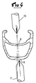
- Figure 4 illustrates the rim drilling operation according to a first mode for implementing the invention.
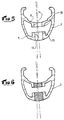
- Figure 5 shows the result of the drilling operation.
- Figure 6 illustrates the next step of tapping the rim holes.
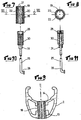
- Figure 7 shows in front view and in section through a transverse plane a insert designed to be screwed into the holes.
- FIG. 8 is a top view and in section of the insert of FIG. 7.
- Figure 9 shows the insert mounted in the rim.
- Figure 10 is a side view of a spoke intended to be assembled to the insert.
- Figure 11 is a view similar to Figure 10 where the elements located the end of the spoke are shown in section.
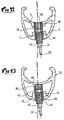
- Figure 12 shows the spoke assembled to the rim.
- Figure 13 is a view similar to Figure 12 and illustrates another mode of implementation of the invention.
- Figure 1 shows a bicycle wheel which includes a rim circular 2 connected to a central hub 3 by spokes 4. Only part of the spokes is shown in this figure.
- the hub has appropriate means to ensure liaison with the framework.
- the rays are distributed in two symmetrical layers, each attached to one end of the hub 3.
- the wheel shown in Figures 1 and 2 is a front wheel.
- one of the plies of spokes is shifted towards the middle part of the hub, so that, on this side, the hub has a tip comprising the freewheel mechanism and serving to support the gearbox gables. This is known to those skilled in the art.
- FIG. 3 shows in cross section and in partial view the rim 2 to raw.
- This rim has in known manner a box structure, with a lower deck 5, an upper deck 6 connected by side walls 7 and 8. These walls extend beyond the upper deck 6 by two wings 9 and 10 which form with bridge 6 an annular channel provided for receiving a tire and a chamber air if applicable.
- the rim shown in the figure is not, however, limiting for the invention, neither as regards the profile of the section, nor as regards the fitting a tire.
- the invention applies in fact as well to the rims provided to be fitted with a tire only rims intended to be fitted with a hose or other tread.
- the rim such as that shown in FIG. 3 is produced at from a profiled bar made of aluminum alloy or another alloy lightweight, which is bent, then assembled end to end by means of a sleeve or by welding. In the raw state, the two bridges are continuous, non-pierced walls.
- Figures 4 and 5 illustrate the drilling operation of the rim.
- This operation consists in known manner of drilling the two bridges of the rim at intervals regular, to allow the hanging of the shelves. It should be noted that the drilling holes takes into account the proper orientation of each radius, this orientation being determined by the general orientation of each layer, and by the number of rays per tablecloth.
- the rims are drilled not using a cutting forest traditional, but through a forest that operates by repression.
- the drilling technique by repression is known in itself.
- Forests used for such drilling have a generally cylindrical shape, with a point in the shape of a punch. The point is shaped with edges, which gives it overall the shape of a pointed pyramid.
- Other forms of tools may also be suitable.
- Two tools 10 and 11 are used in this case to pierce the two bridges. They are mounted coaxially, and are driven in movement from rotation and translation towards the rim by any suitable means.
- the technique of drilling by repression presents the peculiarity of not cut the material, but push it back in the direction of advancement of the forest according to a fireplace.
- the chimneys are oriented towards inside the rim box.
- Push-back drilling can create a burr on the side opposite the fireplace.
- This burr is trimmed or shaped by the drilling tool itself which has at least one deburring tooth for this purpose.
- the burr can also be deburred or shaped by a clean machining operation.
- FIG. 5 represents the rim in cross section at the level of a torque orifices, after drilling and removal of the forests.
- Each bridge 5, 6 has an orifice opening 13, 14 delimited by a chimney 15, 16 which extends towards the interior of the box.
- the two orifices 13 and 14 have the same diameter. This is not limiting, and as will be described later, they may have a different diameter.
- the wall height and its thickness depend on the characteristics of the rim material, the initial thickness of the bridge, the diameter of the forest, and drilling parameters, rotation speed, forward speed, etc.
- the drilling of the orifices by the backflow technique is advantageous in terms of the mechanical strength of the rim.
- the structure of matter no longer exhibits abrupt discontinuity as in the traditional drilling by cutting. Thanks to its peripheral wall, the chimney maintains a certain homogeneity in the structure of the bridges, so that the mechanical resistance to rupture of the rim thus pierced is higher than that of a rim pierced in the traditional way.
- Another advantage is that such discharge drilling does not generate chip, and in particular there is no chip that could break into inside the box.
- FIG. 6 illustrates the next manufacturing step which consists in tapping the two ports 13 and 14 of the bridges. After tapping, it is planned to screw in the two orifices a monobloc insert, so that the two threads are made one depending on the other. If the two holes have the same diameter, we can make the two tapping operations with a single tap in a single pass. If the holes do not have the same diameter, you can use a multi-stage tap, or all other appropriate means.
- the insert 18 intended to be screwed into the two tapped holes is shown in Figures 7 and 8. It is in the form of a portion of tube which is threaded on its outer wall to the diameter and pitch of the orifices 13 and 14. From preferably the length of the insert is equal to or slightly less than the distance between the upper surface of the upper deck 6 and the lower surface of the bridge lower 5, so that once screwed into the two holes of the bridges, the insert is fully integrated inside the perimeter of a rim section.
- the inside of the insert is also tapped with a pitch which is independent of the not external of the insert.
- the interior of the insert has at least in its lower part a polygonal section, for example hexagonal, which is made in the thickness of the thread.
- this hexagonal section allows you to screw the insert into holes 13 and 14 using, for example, a wrench appropriate hexagonal.
- the hexagonal shape serves also anti-rotation guide with a tip located at the end of the spoke.
- Other means may also be suitable for coupling with a tool for screwing the insert, for example one or more grooves made on the internal wall of the insert over all or part of its height, and designed to cooperate with a tool carrying one or more lugs arranged so appropriate.
- the insert could present on the side of the lower deck, i.e. towards the inside of the rim, a projecting extension, with an outer section for example hexagonal which allows the coupling of a screwing tool. This replaces the hexagonal section inside the insert.
- This hexagonal section internal is preferred, however, because it allows weight gain on the inserts, space saving also, and it facilitates the placement of the shelves which will described in more detail later.
- the insert is made of any suitable material, for example alloy aluminum.
- the insert is designed to be screwed into the holes 13 and 14 of the rim, and, from preferably immobilized, by any suitable means, for example by bonding.
- the FIG. 9 illustrates this step of producing the rim equipped with the inserts.
- the insert 18 makes a mechanical connection between the two bridges 5 and 6, which operates in both directions in a longitudinal direction defined by the insert. That is to say that unlike the eyelets which are set on one of the bridges and by simple support on the other, the inserts are here embedded in each of the bridges and they connect the bridges together. The risk of the housing collapsing is considerably reduced.
- the rim structure is stiffened by such connections. It was already stiffened by the discharge chimneys.
- discharge drilling allows a height at each bridge which is much greater than the initial thickness of the wall of the bridge. In other words, we can here implement a screw connection without significantly increase the wall thickness.
- the length of the insert is not limited by manufacturing constraints, so that the distance which separates the two bridges from the rim is chosen without constraint relating to the length of the insert.
- the shape of the lower deck can also be chosen for example more streamlined, because the insert is no longer crimped but screwed inside the rim.
- a spoke intended to be attached to the rim by screwing into the insert is shown in Figures 10 and 11.
- the spoke 25 which is represented is a metal wire with a bent head 26 which is designed to be attached to a lateral flange of a hub, by threading in one of the holes in the flange.
- This is of course not limiting, and the radius could also be straight head, i.e. without elbow, and be assembled by any technique other than threading, for example by simple engagement of the head in a slot in the form of a buttonhole or in a notch.
- the section of the median part of the radius is arbitrary, in particular it can be cylindrical or present an aerodynamic profile.
- the spokes could also be replaced by sticks assembled to the hub or integral therewith, the spoke part which will now be described constituting the end part of such sticks.
- the spokes could also be formed from composite fibers.
- This end portion includes a tip 28 which is secured to the end of the spoke by any appropriate means, for example by screwing and gluing on the threaded end of the spoke.
- the tip could also be assembled by welding, by matting the end of the spoke, or it could be achieved by stamping of the very end of the spoke. According to the method of assembly of the head radius to the hub, in particular by threading or by engagement in a slot, the tip is assembled after or before the spoke placement operation on the hub.
- the end piece 28 has a polygonal section, for example hexagonal which corresponds to the internal section of the insert.
- the tip is provided to be engaged and slide inside the insert 18.
- the fact that the insert has a hexagonal internal section facilitates the positioning of the spoke, even before its Tightening.
- the end of the spoke carries a screw for adjusting tension 30 which is crossed by the spoke, and mounted in free rotation at its end.
- the screw is intended to abut against the end piece 28 and exert on it a thrust inducing by reaction a tension in the radius.
- the screw 30 is also designed to be screwed inside the insert 18, thereby inducing a translation of the nozzle 28 inside the insert.
- the screw tension adjustment is extended on the side opposite the end piece by a sleeve coupling with a tightening tool, for example a section sleeve 31 hexagonal. Any other suitable means is also suitable.
- Figure 12 shows schematically the rim in a section plane including the insert.
- This figure represents the various elements, in particular the insert 18 engaged in the two orifices of the bridges 5 and 6 of the rim, the end piece 28 engaged at sliding in the insert, and the tension adjustment screw 30 partially screwed into the insert, with the coupling sleeve 31 accessible outside the rim which adjusts the spoke tension. It should be noted that when adjusting the tension, the spoke only works at stretching since the end piece 28 prevents the end of the spoke from pivoting. The rays work in better This makes the tension setting more precise.
- the construction which has just been described is capable of being carried out with many variations.
- a forest that performs in the same operation the tapping of one at least holes.
- self-tapping inserts that's say that create their own thread when screwing them.
- Another variant would consist of tapping only one orifice, for example the orifice of the lower deck, and ensuring the connection with the other bridge by a self-tapping section of the insert.
- the two orifices could be drilled by a single forest oriented operating on the upper deck then on the lower deck. Such drilling would have to orient the chimney of the lower deck towards the outside of the box.
- the two orifices could have different diameters, the insert in this case having a shoulder on which it can be supported to ensure its tightening in the holes.
- Figure 13 shows another mode of implementation of the invention.
- only the lower bridge 35 of the rim 32 is drilled using the discharge technique, so as to create a chimney 37.
- the upper bridge 36 is not pierced, it remains in the raw state.
- an insert 38 is engaged by screwing in the chimney 37, and tightened against the upper deck. Insert 38 looks like previous insert 18, with an internal wall threaded and machined in a hexagonal section.
- the radius 39 intended to cooperate with the insert 38 is entirely similar to the previous spoke, with a tip 40 of hexagonal section at its end, a tension adjustment screw 41 extended by a coupling sleeve with a clamping tool.
- Such a construction has the advantage that the rim is waterproof, it is say that on the side of the tire, it has a continuous bridge, not drilled except in the case if necessary for mounting the valve.
- a rim is suitable for a tubeless tire fitting, or a fitting where only part of the volume defined by the tire is occupied by an inner tube or a material of filling, the other part being occupied by pressurized air injected between the rim and tire.
- This other embodiment of the invention is also susceptible variants of the same nature as that which have been previously described.
Abstract
Description
L'invention concerne un procédé de perçage d'une jante de roue à rayons. L'invention concerne également un jante obtenue par la mise en oeuvre du procédé. L'invention concerne également un rayon, un écrou de rayon prévus pour équiper la jante obtenue par le procédé, ainsi une roue obtenue par l'assemblage de la jante avec de tels rayons et écrous de rayons.The invention relates to a method for drilling a spoke wheel rim. The invention also relates to a rim obtained by the use of the process. The invention also relates to a spoke, a spoke nut provided for equip the rim obtained by the process, thus a wheel obtained by the assembly of the rim with such spokes and spoke nuts.
De façon connue, une roue, notamment de bicyclette, comprend un moyeu central relié par deux nappes de rayons à une jante circulaire. La jante est formée de deux ponts circulaires reliés par deux flancs latéraux de façon à former un caisson. Les flancs latéraux se prolongent vers l'extérieur par deux ailes, de façon à former avec le pont supérieur un canal annulaire prévu pour recevoir un pneumatique. Pour certaines jantes qui sont prévues pour recevoir un boyau, le canal est une simple rainure formée par un affaissement du pont supérieur vers l'intérieur. Les rayons sont reliés à la jante par des écrous vissés à l'extrémité des rayons. Ces écrous permettent par ailleurs de régler la tension des rayons.In a known manner, a wheel, in particular a bicycle, comprises a hub central connected by two plies of spokes to a circular rim. The rim is formed of two circular bridges connected by two lateral flanks so as to form a box. The lateral flanks extend outwards by two wings, so to form with the upper deck an annular channel intended to receive a pneumatic. For some rims that are intended to receive a tubular tire, the channel is a simple groove formed by a subsidence of the upper bridge towards the interior. The spokes are connected to the rim by nuts screwed to the end of the rays. These nuts also make it possible to adjust the spoke tension.
Pour recevoir les écrous de rayons, de façon usuelle, les deux ponts de la jante sont percés d'orifices répartis à la circonférence de la jante. Les orifices du pont inférieur sont prévus pour servir d'assise aux têtes d'écrous. Les orifices du pont supérieur, de diamètre supérieur, sont prévus pour permettre la mise en place de l'écrou de rayon depuis l'extérieur.To receive the spoke nuts, in the usual way, the two bridges of the rim are pierced with holes distributed around the circumference of the rim. The orifices of the lower deck are intended to serve as a seat for the nut heads. The orifices of the upper deck, of larger diameter, are provided to allow the installation spoke nut from the outside.
Pour améliorer les conditions dans lesquelles la tête d'écrou prend appui contre la jante, et la répartition dans la jante des contraintes induites par la tension des rayons, il est connu d'équiper les jantes avec des oeillets qui traversent les orifices du pont inférieur. Ces oeillets sont assemblées par un sertissage à la périphérie de l'orifice du pont inférieur. Ils présentent par ailleurs un corps d'oeillet en forme de cuvette dont la partie inférieure repose sur le pont inférieur, et la partie supérieure présente un rebord qui s'appuie contre le pont supérieur. Le fond des oeillets est percé pour le passage du corps d'écrou. Ces oeillets sont avantageux car ils établissent des liaisons mécaniques entre les deux ponts, ce qui renforce la structure de la jante et sa résistance à la déformation.To improve the conditions under which the nut head is supported against the rim, and the distribution in the rim of stresses induced by tension spokes, it is known to equip the rims with eyelets which pass through the holes in the lower deck. These eyelets are assembled by crimping to the periphery of the opening of the lower deck. They also have an eyelet body bowl-shaped, the lower part of which rests on the lower deck, and the part upper has a ledge which leans against the upper deck. The bottom of eyelets is drilled for the passage of the nut body. These eyelets are advantageous because they establish mechanical connections between the two bridges, which reinforces the rim structure and its resistance to deformation.
Un oeillet monobloc est décrit dans la demande de brevet EP 130 449. Ces oeillets existent aussi en deux éléments distincts assemblés au niveau du sertissage.A monobloc eyelet is described in patent application EP 130 449. These eyelets also exist in two separate elements assembled at the crimping.
Cependant, pour de telles jantes, les orifices des ponts constituent des zones de faiblesse locales qui fragilisent chacun des deux ponts. De plus, ces orifices doivent avoir des dimensions relativement importantes. les orifices du pont inférieur doivent en effet avoir un diamètre suffisant pour permettre le passage du corps de l'écrou, et sa rotation libre. Les orifices du pont supérieur doivent permettre le passage de la tête d'écrou dont dépend l'accrochage du rayon à la jante ainsi que les outils de réglage.However, for such rims, the holes in the bridges constitute zones local weaknesses which weaken each of the two bridges. In addition, these orifices must have relatively large dimensions. the holes of the lower deck must have a sufficient diameter to allow the passage of the body of the nut, and its free rotation. The openings on the upper deck must allow passage of the nut head on which the attachment of the spoke to the rim depends as well as adjustment tools.
Un autre problème de ces jantes est que lors du réglage de la tension des rayons, le rayon lui-même est sollicité en torsion et vrille sur lui-même avant qu'un mouvement relatif se produise au niveau des filets de liaison avec l'écrou. De ce fait, le réglage en tension des rayons est relativement imprécis, et les rayons ne travaillent pas dans les meilleures conditions.Another problem with these rims is that when adjusting the tension of the spokes, the spoke itself is twisted and twists on itself before a relative movement occurs at the threads connecting with the nut. From this done, the spoke tension adjustment is relatively imprecise, and the spokes do not not work in the best conditions.
Un autre problème de ces jantes vient de la fabrication des oeillets. En effet, si l'on souhaite équiper la jante d'oeillets doubles en forme de cuvette, la distance entre les deux ponts de la jante est directement liée à la hauteur de la cuvette de l'oeillet. L'oeillet étant réalisé de façon usuelle en acier inox par emboutissage, la hauteur maximale d'un oeillet est de ce fait limitée, ce qui impose des contraintes de dimensions pour la jante.Another problem with these rims comes from the manufacture of eyelets. Indeed, if we want to equip the rim with double eyelets in the shape of a bowl, the distance between the two rim bridges is directly related to the height of the the carnation. The eyelet being produced in the usual way in stainless steel by stamping, the maximum height of an eyelet is therefore limited, which imposes constraints dimensions for the rim.
On connaít cependant d'après la demande de brevet publiée sous le numéro WO 93/09963 un jante présentant des orifices qui sont taraudés. L'extrémité filetée des rayons est reliée à cette jante par l'intermédiaire d'un écrou fileté à l'intérieur et taraudé à l'extérieur avec des pas différents. Cette jante présente de plus un pont supérieur non percé sauf le cas échéant pour le montage d'une valve, ce qui rend la jante étanche à l'air, et donc approprié pour le montage d'un pneu de type tubeless.However, we know from the patent application published under the number WO 93/09963 a rim having holes which are tapped. The threaded end spokes is connected to this rim via a threaded nut on the inside and tapped outside with different steps. This rim also has a bridge upper not drilled except where necessary for mounting a valve, which makes the airtight rim, and therefore suitable for mounting a tire type tubeless.
Cependant, le pont inférieur qui est percé et taraudé doit être renforcé en épaisseur pour supporter les contraintes d'où une augmentation indésirable du poids et de l'inertie de la jante. Le mode de montage des rayons ne résout pas non plus le problème du vrillage des rayons.However, the lower deck which is drilled and tapped must be reinforced by thickness to withstand the stresses resulting in an undesirable increase in weight and inertia of the rim. The mounting mode of the shelves does not solve no plus the problem of the twisting of the spokes.
Un but de l'invention est de proposer un procédé de perçage d'une jante qui permette d'obtenir une jante avec des caractéristiques mécaniques améliorées sans augmentation significative du poids.An object of the invention is to propose a method for drilling a rim which provides a rim with improved mechanical characteristics without significant increase in weight.
Un autre but de l'invention est de proposer une jante percée d'orifices qui présente une résistance améliorée à la rupture.Another object of the invention is to propose a rim pierced with orifices which has improved breaking strength.
Un autre but de l'invention est de proposer une jante dont la distance entre les deux ponts est libérée de la contrainte de hauteur limite des cuvettes d'oeillets.Another object of the invention is to propose a rim whose distance between the two bridges are freed from the height limit constraint of the eyelet cups.
Un autre but de l'invention est de proposer une roue équipée de rayons dont les conditions de travail en traction sont améliorées.Another object of the invention is to provide a wheel fitted with spokes, working conditions in traction are improved.
D'autres buts et avantages de l'invention apparaítront au cours de la description qui va suivre.Other objects and advantages of the invention will become apparent during the course of the description which follows.
Selon l'invention, le procédé de réalisation d'une jante percée d'orifices prévus pour recevoir des rayons de liaison avec un moyeu, la jante présentant un caisson avec un pont supérieur et un pont inférieur est caractérisé par le fait qu'au moins le pont inférieur est percé d'un orifice débouchant au moyen d'un foret de perçage par refoulement opérant en direction du pont supérieur.According to the invention, the method of producing a rim pierced with orifices designed to receive connecting spokes with a hub, the rim having a box with an upper deck and a lower deck is characterized in that at minus the lower deck is pierced with an opening opening by means of a drill discharge drilling operating in the direction of the upper deck.
La jante obtenue par la mise en oeuvre du procédé est caractérisée par le fait qu'au moins l'un des ponts présente une pluralité d'orifices débouchants délimités par une cheminée de refoulement de hauteur supérieur à l'épaisseur du pont.The rim obtained by implementing the method is characterized by the fact that at least one of the bridges has a plurality of delimited through orifices by a discharge chimney with a height greater than the thickness of the bridge.
Le rayon prévu pour équiper la jante précédente est caractérisé par le fait qu'il présente un embout assemblé solidairement à l'extrémité du rayon, et une vis de réglage de tension monté en rotation libre en retrait par rapport à l'embout.The radius provided to equip the previous rim is characterized by the fact that it has a tip joined together at the end of the spoke, and a screw of tension adjustment mounted in free rotation recessed with respect to the end piece.
La roue selon l'invention présente une jante telle que précitée, un moyeu central et des rayons de liaison entre la jante et le moyeu.The wheel according to the invention has a rim as mentioned above, a hub central and connecting spokes between the rim and the hub.
Selon une autre caractéristique, la jante comprend au moins un rayon tel que précité.According to another characteristic, the rim comprises at least one spoke such that cited above.
L'invention sera mieux comprise en se référant à la description ci-dessous et aux dessins en annexe qui en font partie intégrante.The invention will be better understood by referring to the description below and the annexed drawings which form an integral part thereof.
La figure 1 est une vue générale de côté d'une roue.Figure 1 is a general side view of a wheel.
La figure 2 est une vue de face de la roue de la figure 1.Figure 2 is a front view of the wheel of Figure 1.
La figure 3 est une vue partielle de face et en coupe par un plan de section transversal d'une jante à l'état brut.Figure 3 is a partial front view and in section through a section plane transverse of a rim in the rough.
La figure 4 illustre l'opération de perçage de la jante selon un premier mode de mise en oeuvre de l'invention.Figure 4 illustrates the rim drilling operation according to a first mode for implementing the invention.
La figure 5 montre le résultat de l'opération de perçage.Figure 5 shows the result of the drilling operation.
La figure 6 illustre l'étape suivante de taraudage des orifices de la jante.Figure 6 illustrates the next step of tapping the rim holes.
La figure 7 montre en vue de face et en coupe par un plan transversal un insert prévu pour être vissé dans les orifices.Figure 7 shows in front view and in section through a transverse plane a insert designed to be screwed into the holes.
La figure 8 est une vue de dessus et en coupe de l'insert de la figure 7.FIG. 8 is a top view and in section of the insert of FIG. 7.
La figure 9 montre l'insert monté dans la jante.Figure 9 shows the insert mounted in the rim.
La figure 10 est une vue de côté d'un rayon prévu pour être assemblé à l'insert.Figure 10 is a side view of a spoke intended to be assembled to the insert.
la figure 11 est une vue semblable à la figure 10 où les éléments situés à l'extrémité du rayon sont représentés en coupe.Figure 11 is a view similar to Figure 10 where the elements located the end of the spoke are shown in section.
La figure 12 montre le rayon assemblé à la jante.Figure 12 shows the spoke assembled to the rim.
La figure 13 est une vue semblable à la figure 12 et illustre un autre mode de mise en oeuvre de l'invention.Figure 13 is a view similar to Figure 12 and illustrates another mode of implementation of the invention.
La figure 1 représente une roue de bicyclette qui comprend une jante
circulaire 2 reliée à un moyeu central 3 par des rayons 4. Seule une partie des
rayons est représentée dans cette figure. De façon connue, le moyeu présente des
moyens appropriés pour assurer la liaison avec le cadre. Tel que cela est visible
dans la figure 2, les rayons sont répartis selon deux nappes symétriques, chacune
accrochée à une extrémité du moyeu 3. Figure 1 shows a bicycle wheel which includes a rim
circular 2 connected to a
La roue représentée dans les figures 1 et 2 est une roue avant. Dans le cas d'une roue arrière de façon usuelle, l'une des nappes de rayons est décalée vers la partie médiane du moyeu, pour que, de ce côté, le moyeu présente un embout comprenant le mécanisme de roue libre et servant de support au boítier de pignons. Ceci est connu de l'homme de métier.The wheel shown in Figures 1 and 2 is a front wheel. In the case of a rear wheel in the usual way, one of the plies of spokes is shifted towards the middle part of the hub, so that, on this side, the hub has a tip comprising the freewheel mechanism and serving to support the gearbox gables. This is known to those skilled in the art.
La figure 3 représente en section transversale et en vue partielle la jante 2 à
l'état brut . Cette jante présente de façon connue une structure en caisson, avec un
pont inférieur 5, un pont supérieur 6 reliés par des parois latérales 7 et 8. Ces
parois se prolongent au delà du pont supérieur 6 par deux ailes 9 et 10 qui forment
avec le pont 6 un canal annulaire prévu pour recevoir un pneu et une chambre à
air le cas échéant.Figure 3 shows in cross section and in partial view the
La jante représentée dans la figure n'est cependant pas limitative pour l'invention, ni en ce qui concerne le profil de la section, ni en ce qui concerne le montage d'un pneu. L'invention s'applique en effet aussi bien aux jantes prévues pour être équipées d'un pneu que des jantes prévues pour être équipées d'un boyau ou de tout autre bandage de roulement.The rim shown in the figure is not, however, limiting for the invention, neither as regards the profile of the section, nor as regards the fitting a tire. The invention applies in fact as well to the rims provided to be fitted with a tire only rims intended to be fitted with a hose or other tread.
De façon connue, la jante telle que celle représentée en figure 3 est réalisée à partir d'un barreau profilé réalisé en alliage d'aluminium ou d'un autre alliage léger, qui est cintré, puis assemblé bout à bout au moyen d'un manchon ou par soudure. A l'état brut, les deux ponts sont des parois continues non percées.In a known manner, the rim such as that shown in FIG. 3 is produced at from a profiled bar made of aluminum alloy or another alloy lightweight, which is bent, then assembled end to end by means of a sleeve or by welding. In the raw state, the two bridges are continuous, non-pierced walls.
Les figures 4 et 5 illustrent l'opération de perçage de la jante. Cette opération consiste de façon connue à percer les deux ponts de la jante à intervalles réguliers, afin de permettre l'accrochage des rayons. Il faut souligner que le perçage des orifices tient compte de l'orientation propre de chaque rayon, cette orientation étant déterminée par l'orientation générale de chaque nappe, et par le nombre de rayons par nappe.Figures 4 and 5 illustrate the drilling operation of the rim. This operation consists in known manner of drilling the two bridges of the rim at intervals regular, to allow the hanging of the shelves. It should be noted that the drilling holes takes into account the proper orientation of each radius, this orientation being determined by the general orientation of each layer, and by the number of rays per tablecloth.
Selon l'invention, les jantes sont percées non pas à l'aide d'un forêt de coupe traditionnel, mais par un forêt qui opère par refoulement. La technique de perçage par refoulement est connue en elle-même. Les forêts utilisés pour un tel perçage ont une forme générale cylindrique, avec une pointe en forme de poinçon. La pointe est façonnée avec des arêtes, ce qui lui donne globalement la forme d'une pyramide pointue. D'autres formes d'outils peuvent également convenir.According to the invention, the rims are drilled not using a cutting forest traditional, but through a forest that operates by repression. The drilling technique by repression is known in itself. Forests used for such drilling have a generally cylindrical shape, with a point in the shape of a punch. The point is shaped with edges, which gives it overall the shape of a pointed pyramid. Other forms of tools may also be suitable.
Deux outils 10 et 11 sont utilisés dans le cas présent pour percer les deux
ponts. Ils sont montés de façon coaxiale, et sont entraínés en mouvement de
rotation et de translation en direction de la jante par tout moyen approprié.Two
La technique de perçage par refoulement présente la particularité de ne pas découper la matière, mais de la repousser dans le sens d'avancement du forêt selon une cheminée. Dans le cas présent, les cheminées sont orientées vers l'intérieur du caisson de la jante. The technique of drilling by repression presents the peculiarity of not cut the material, but push it back in the direction of advancement of the forest according to a fireplace. In this case, the chimneys are oriented towards inside the rim box.
Le perçage par refoulement peut créer une bavure du côté opposé à la cheminée. Cette bavure est ébarbée ou mise en forme par l'outil de perçage luimême qui présente au moins une dent d'ébarbage à cet effet. La bavure peut également être ébarbée ou mise en forme par une opération d'usinage propre.Push-back drilling can create a burr on the side opposite the fireplace. This burr is trimmed or shaped by the drilling tool itself which has at least one deburring tooth for this purpose. The burr can also be deburred or shaped by a clean machining operation.
La figure 5 représente la jante en section transversale au niveau d'un couple
d'orifices, après perçage et retrait des forêts. Chaque pont 5, 6 présente un orifice
débouchant 13, 14 délimité par une cheminée 15, 16 qui s'étend vers l'intérieur du
caisson. Dans le mode de réalisation illustré, les deux orifices 13 et 14 présentent
le même diamètre. Ce n'est pas limitatif, et comme cela sera décrit ultérieurement,
ils peuvent avoir un diamètre différent.FIG. 5 represents the rim in cross section at the level of a torque
orifices, after drilling and removal of the forests. Each
Pour chaque cheminée, la hauteur de paroi, et son épaisseur dépendent des caractéristiques du matériau de la jante, de l'épaisseur initiale du pont, du diamètre du forêt, et des paramètres de perçage, vitesse de rotation, vitesse d'avancement, etc.For each chimney, the wall height and its thickness depend on the characteristics of the rim material, the initial thickness of the bridge, the diameter of the forest, and drilling parameters, rotation speed, forward speed, etc.
On a pu obtenir les résultats suivants.The following results were obtained.
Pour une jante réalisée en alliage d'aluminium 6106, on a percé un pont de 1,5 mm d'épaisseur avec un forêt de 5,5 mm de diamètre. La cheminée obtenue avait une longueur utile de 5 mm environ, cette longueur incluant l'épaisseur du pont.For a rim made of aluminum alloy 6106, a bridge has been drilled 1.5 mm thick with a 5.5 mm diameter forest. The chimney obtained had a useful length of approximately 5 mm, this length including the thickness of the bridge.
Il faut souligner ici que le perçage des orifices par la technique de refoulement est avantageux sur le plan de la résistance mécanique de la jante. En effet, la structure de la matière ne présente plus de discontinuité brutale comme dans le cas d'un perçage traditionnel par découpe. Grâce à sa paroi périphérique, la cheminée maintient une certaine homogénéité de la structure des ponts, si bien que la résistance mécanique à la rupture de la jante ainsi percée est plus élevée que celle d'une jante percée de façon traditionnelle.It should be emphasized here that the drilling of the orifices by the backflow technique is advantageous in terms of the mechanical strength of the rim. Indeed, the structure of matter no longer exhibits abrupt discontinuity as in the traditional drilling by cutting. Thanks to its peripheral wall, the chimney maintains a certain homogeneity in the structure of the bridges, so that the mechanical resistance to rupture of the rim thus pierced is higher than that of a rim pierced in the traditional way.
Un autre avantage est qu'un tel perçage par refoulement ne génère pas de copeau, et en particulier il n'y a pas de copeau qui pourraient s'introduire à l'intérieur du caisson.Another advantage is that such discharge drilling does not generate chip, and in particular there is no chip that could break into inside the box.
Enfin, les deux cheminées sont orientées vers l'intérieur du caisson, il n'y a donc pas de partie saillante vers l'extérieur, en particulier du côté prévu pour le pneu et la chambre à air.Finally, the two chimneys are oriented towards the inside of the box, there is therefore no projecting part towards the outside, in particular on the side provided for the tire and inner tube.
La figure 6 illustre l'étape suivante de fabrication qui consiste à tarauder les
deux orifices 13 et 14 des ponts. Après taraudage, il est prévu de visser dans les
deux orifices un insert monobloc, si bien que les deux taraudages sont réalisés l'un
en fonction de l'autre. Si les deux trous ont même diamètre, on peut réaliser les
deux opérations de taraudage avec un taraud unique en une seule passe. Si les
orifices n'ont pas le même diamètre, on peut utiliser un taraud à étages, ou tout
autre moyen approprié. FIG. 6 illustrates the next manufacturing step which consists in tapping the
two
L'insert 18 prévu pour être vissé dans les deux orifices taraudés est
représenté en figures 7 et 8. Il se présente sous la forme d'une portion de tube qui
est filetée à sa paroi externe au diamètre et au pas des orifices 13 et 14. De
préférence, la longueur de l'insert est égale ou légèrement inférieure à la distance
entre la surface supérieure du pont supérieur 6 et la surface inférieure du pont
inférieur 5 , pour que une fois vissé dans les deux orifices des ponts, l'insert soit
intégré totalement à l'intérieur du périmètre d'une section de la jante.The
L'intérieur de l'insert est également taraudé à un pas qui est indépendant du
pas externe de l'insert. De plus, l'intérieur de l'insert présente au moins dans sa
partie inférieure une section polygonale, par exemple hexagonale, qui est réalisée
dans l'épaisseur du filetage. En premier lieu, cette section hexagonale permet de
visser l'insert dans les orifices 13 et 14 au moyen, par exemple, d'une clé
hexagonale appropriée. Comme cela apparaítra plus loin, la forme hexagonale sert
également de guidage anti-rotation à un embout situé à l'extrémité du rayon. La
figure 8 représente l'insert 18 vu de dessus, avec son corps 19, sur l'extérieur du
corps, un filet 20 du filetage externe, et sur l'intérieur du corps, un filet 21 de
taraudage sectionné par six saignées triangulaires 22 qui sont réparties aux
sommets d'un hexagone, et définissent ensemble une section hexagonale.The inside of the insert is also tapped with a pitch which is independent of the
not external of the insert. In addition, the interior of the insert has at least in its
lower part a polygonal section, for example hexagonal, which is made
in the thickness of the thread. First, this hexagonal section allows you to
screw the insert into
D'autres moyens peuvent aussi convenir pour assurer l'accouplement avec un outil afin de réaliser le vissage de l'insert, par exemple une ou plusieurs rainures réalisées à la paroi interne de l'insert sur tout ou partie de sa hauteur, et prévues pour coopérer avec un outil portant un ou des ergots disposées de façon appropriée.Other means may also be suitable for coupling with a tool for screwing the insert, for example one or more grooves made on the internal wall of the insert over all or part of its height, and designed to cooperate with a tool carrying one or more lugs arranged so appropriate.
Egalement, l'insert pourrait présenter du côté du pont inférieur, c'est à dire vers l'intérieur de la jante, un prolongement en saillie, avec une section extérieur par exemple hexagonale qui permette l'accouplement d'un outil de vissage. Ceci remplace la section hexagonale à l'intérieur de l'insert. Cette section hexagonale interne est toutefois préférée, car elle permet un gain de poids sur les inserts, un gain de place également, et elle facilite la mise en place des rayons qui sera décrite plus en détails ultérieurement.Also, the insert could present on the side of the lower deck, i.e. towards the inside of the rim, a projecting extension, with an outer section for example hexagonal which allows the coupling of a screwing tool. This replaces the hexagonal section inside the insert. This hexagonal section internal is preferred, however, because it allows weight gain on the inserts, space saving also, and it facilitates the placement of the shelves which will described in more detail later.
L'insert est réalisé en tout matériau approprié, par exemple en alliage d'aluminium.The insert is made of any suitable material, for example alloy aluminum.
L'insert est prévu pour être vissé dans les orifices 13 et 14 de la jante, et, de
préférence immobilisé, par tout moyen approprié, par exemple par collage. La
figure 9 illustre cette étape de réalisation de la jante équipée des inserts.The insert is designed to be screwed into the
Avantageusement l'insert 18 réalise une liaison mécanique entre les deux
ponts 5 et 6, qui opère dans les deux sens d'une direction longitudinale définie par
l'insert. C'est à dire que contrairement aux oeillets qui sont sertis sur l'un des ponts
et en appui simple sur l'autre, les inserts sont ici encastrés dans chacun des ponts
et ils relient les ponts de façon solidaires. Le risque d'affaissement du caisson est
considérablement réduit. La structure de la jante se trouve rigidifiée par de telles
liaisons. Elle se trouvait déjà rigidifiée par les cheminées de refoulement. En outre,
le perçage par refoulement permet d'avoir au niveau de chaque pont une hauteur
de taraudage qui est bien supérieure à l'épaisseur initiale de la paroi du pont. En
d'autres termes, on peut ici mettre en oeuvre une liaison par vissage sans
augmenter de façon significative l'épaisseur de paroi. Par ailleurs, la longueur de
l'insert n'est pas limitée par des contraintes de fabrication, si bien que la distance
qui sépare les deux ponts de la jante est choisie sans contrainte relative à la
longueur de l'insert. La forme du pont inférieur peut aussi être choisie par exemple
plus profilée, car l'insert n'est plus serti mais vissé à l'intérieur de la jante.Advantageously, the
Un rayon prévu pour être accroché à la jante par vissage dans l'insert est représenté en figures 10 et 11.A spoke intended to be attached to the rim by screwing into the insert is shown in Figures 10 and 11.
Le rayon 25 qui est représenté est un fil métallique avec une tête coudée 26
qui est prévue pour être accrochée à un flasque latéral d'un moyeu, par enfilage
dans l'un des orifices du flasque. Ceci n'est naturellement pas limitatif, et le rayon
pourrait également être à tête droite, c'est à dire sans coude, et être assemblé par
toute autre technique que l'enfilage, par exemple par simple engagement de la tête
dans un logement en forme de boutonnière ou dans une encoche. La section de la
partie médiane du rayon est quelconque, notamment elle peut être cylindrique ou
présenter un profil aérodynamique. Les rayons pourraient aussi être remplacés par
des bâtons assemblés au moyeu ou monobloc avec celui-ci, la partie des rayons
qui va maintenant être décrite constituant la partie d'extrémité de tels bâtons.The
Les rayons pourraient aussi être formés à partir de fibres composites.The spokes could also be formed from composite fibers.
Cette partie d'extrémité comprend un embout 28 qui est solidarisé à
l'extrémité du rayon par tout moyen approprié, par exemple par vissage et collage
sur l'extrémité filetée du rayon. L'embout pourrait également être assemblé par
soudure, par matage de l'extrémité du rayon, ou il pourrait être réalisé par
matriçage de l'extrémité même du rayon. Selon le mode d'assemblage de la tête
de rayon au moyeu, notamment par enfilage ou par engagement dans une fente,
l'embout est assemblé après ou avant l'opération de mise en place du rayon sur le
moyeu.This end portion includes a
L'embout 28 présente une section de forme polygonale, par exemple
hexagonale qui correspond à la section interne de l'insert. L'embout est prévu
pour être engagé et coulisser à l'intérieur de l'insert 18. Le fait que l'insert présente
une section interne hexagonale facilite la mise en place du rayon, avant même son
serrage.The
La coopération entre les sections hexagonales de l'embout de rayon et de l'insert a pour effet de retenir en rotation l'extrémité du rayon, c'est à dire que cela empêche tout vrillage du rayon. Comme cela a déjà été dit précédemment à propos de la section hexagonale de l'insert, tout autre moyen approprié remplissant cette fonction convient.The cooperation between the hexagonal sections of the spoke tip and the insert has the effect of retaining in rotation the end of the spoke, that is to say that prevents any twisting of the spoke. As has already been said previously about of the hexagonal section of the insert, any other appropriate means fulfilling this function is suitable.
En arrière de l'embout, l'extrémité du rayon porte une vis de réglage de
tension 30 qui est traversée par le rayon, et montée en rotation libre à son
extrémité. La vis est prévue pour buter contre l'embout 28 et exercer sur lui une
poussée induisant par réaction une tension dans le rayon. La vis 30 est également
prévue pour être vissée à l'intérieur de l'insert 18, induisant par là une translation
de l'embout 28 à l'intérieur de l'insert.Behind the end piece, the end of the spoke carries a screw for adjusting
De préférence, comme cela est représenté dans les figures 10 et 11, la vis de
réglage de tension se prolonge du côté opposé à l'embout par un manchon
d'accouplement avec un outil de serrage, par exemple un manchon 31 de section
hexagonale. Tout autre moyen approprié convient également.Preferably, as shown in Figures 10 and 11, the screw
tension adjustment is extended on the side opposite the end piece by a sleeve
coupling with a tightening tool, for example a
La figure 12 montre schématiquement la jante dans un plan de section incluant l'insert.Figure 12 shows schematically the rim in a section plane including the insert.
Cette figure représente les différents éléments, notamment l'insert 18 engagé
dans les deux orifices des ponts 5 et 6 de la jante, l'embout 28 engagé à
coulissement dans l'insert, et la vis 30 de réglage de tension en partie vissée dans
l'insert, avec le manchon d'accouplement 31 accessible à l'extérieur de la jante qui
permet de régler la tension du rayon. Il faut souligner que lors d'un réglage de
tension, le rayon ne travaille qu'à l'étirement étant donné que l'embout 28
empêche l'extrémité du rayon de pivoter. Les rayons travaillent dans de meilleures
conditions et le réglage de tension est de ce fait plus précis.This figure represents the various elements, in particular the
La construction qui vient d'être décrite est susceptible d'être réalisée avec de nombreuses variantes. Pour la liaison entre la jante et l'insert, il serait possible, par exemple, d'utiliser un forêt qui réalise dans la même opération le taraudage de l'un au moins des orifices. On pourrait aussi utiliser des inserts auto-taraudeurs, c'est à dire qui créent leur propre filetage lors de leur vissage. Une autre variante consisterait à ne tarauder qu'un seul orifice, par exemple l'orifice du pont inférieur, et d'assurer la liaison avec l'autre pont par une section auto-taraudeuse de l'insert. Selon une autre variante, les deux orifices pourraient être percés par un seul forêt orienté opérant sur le pont supérieur puis sur le pont inférieur. Un tel perçage aurait pour effet d'orienter la cheminée du pont inférieur vers l'extérieur du caisson. Selon une autre variante, les deux orifices pourraient avoir des diamètres différents, l'insert ayant dans ce cas un épaulement sur lequel il peut s'appuyer pour assurer son serrage dans les orifices. On pourrait également utiliser un insert borgne du côté du pont supérieur.The construction which has just been described is capable of being carried out with many variations. For the connection between the rim and the insert, it would be possible, by example, using a forest that performs in the same operation the tapping of one at least holes. We could also use self-tapping inserts, that's say that create their own thread when screwing them. Another variant would consist of tapping only one orifice, for example the orifice of the lower deck, and ensuring the connection with the other bridge by a self-tapping section of the insert. According to another variant, the two orifices could be drilled by a single forest oriented operating on the upper deck then on the lower deck. Such drilling would have to orient the chimney of the lower deck towards the outside of the box. According to another variant, the two orifices could have different diameters, the insert in this case having a shoulder on which it can be supported to ensure its tightening in the holes. We could also use a blind insert of side of the upper deck.
A ce sujet, la figure 13 montre un autre mode de mise en oeuvre de
l'invention. Selon ce mode de mise en oeuvre, seul le pont inférieur 35 de la jante
32 est percé selon la technique de refoulement, de façon à créer une cheminée 37.
Le pont supérieur 36 n'est pas percé, il reste à l'état brut. Comme dans le cas
précédent, un insert 38 est engagé par vissage dans la cheminée 37, et serré
contre le pont supérieur. L'insert 38 se présente comme l'insert 18 précédent, avec
une paroi interne taraudée et usinée selon une section hexagonale.In this regard, Figure 13 shows another mode of implementation of
the invention. According to this embodiment, only the
Le rayon 39 prévu pour coopérer avec l'insert 38 est tout à fait semblable au
rayon précédent, avec à son extrémité un embout 40 de section hexagonale, une
vis 41 de réglage de tension prolongée par un manchon d'accouplement avec un
outil de serrage.The
Une telle construction présente l'avantage que la jante est étanche, c'est à dire que du côté du pneu, elle présente un pont continu, non percé sauf le cas échéant pour le montage de la valve. Une telle jante est approprié pour un montage de pneu de type tubeless, ou un montage où une partie seulement du volume défini par le pneu est occupée par une chambre à air ou un matériau de remplissage, l'autre partie étant occupée par de l'air sous pression injecté entre la jante et le pneu.Such a construction has the advantage that the rim is waterproof, it is say that on the side of the tire, it has a continuous bridge, not drilled except in the case if necessary for mounting the valve. Such a rim is suitable for a tubeless tire fitting, or a fitting where only part of the volume defined by the tire is occupied by an inner tube or a material of filling, the other part being occupied by pressurized air injected between the rim and tire.
Cet autre mode de mise en oeuvre de l'invention est également susceptible de variantes de même nature que celle qui ont été précédemment décrites.This other embodiment of the invention is also susceptible variants of the same nature as that which have been previously described.
Claims (13)
Priority Applications (1)
| Application Number | Priority Date | Filing Date | Title |
|---|---|---|---|
| EP05003972A EP1531062B1 (en) | 1996-07-12 | 1997-07-05 | Process for drilling a spoke wheel, rim drilled according this process, insert adapted to equip the rim, and wheel particularly for cycle |
Applications Claiming Priority (2)
| Application Number | Priority Date | Filing Date | Title |
|---|---|---|---|
| FR9609047 | 1996-07-12 | ||
| FR9609047A FR2750913B1 (en) | 1996-07-12 | 1996-07-12 | METHOD OF DRILLING A SPOKED RIM, RIM DRILLED ACCORDING TO THE METHOD, INSERT SUITABLE FOR EQUIPMENT ON THE RIM, AND WHEEL IN PARTICULAR FOR A CYCLE |
Related Child Applications (1)
| Application Number | Title | Priority Date | Filing Date |
|---|---|---|---|
| EP05003972A Division EP1531062B1 (en) | 1996-07-12 | 1997-07-05 | Process for drilling a spoke wheel, rim drilled according this process, insert adapted to equip the rim, and wheel particularly for cycle |
Publications (2)
| Publication Number | Publication Date |
|---|---|
| EP0818328A1 true EP0818328A1 (en) | 1998-01-14 |
| EP0818328B1 EP0818328B1 (en) | 2006-08-30 |
Family
ID=9494219
Family Applications (2)
| Application Number | Title | Priority Date | Filing Date |
|---|---|---|---|
| EP97111387A Expired - Lifetime EP0818328B1 (en) | 1996-07-12 | 1997-07-05 | Process for building a spoke wheel,rim drilled according the process,insert adapted to equip the rim,and wheel paricularly for cycle |
| EP05003972A Expired - Lifetime EP1531062B1 (en) | 1996-07-12 | 1997-07-05 | Process for drilling a spoke wheel, rim drilled according this process, insert adapted to equip the rim, and wheel particularly for cycle |
Family Applications After (1)
| Application Number | Title | Priority Date | Filing Date |
|---|---|---|---|
| EP05003972A Expired - Lifetime EP1531062B1 (en) | 1996-07-12 | 1997-07-05 | Process for drilling a spoke wheel, rim drilled according this process, insert adapted to equip the rim, and wheel particularly for cycle |
Country Status (4)
| Country | Link |
|---|---|
| US (2) | US6224165B1 (en) |
| EP (2) | EP0818328B1 (en) |
| DE (2) | DE69736577T2 (en) |
| FR (1) | FR2750913B1 (en) |
Cited By (8)
| Publication number | Priority date | Publication date | Assignee | Title |
|---|---|---|---|---|
| FR2793444A1 (en) * | 1999-05-12 | 2000-11-17 | Mavic Sa | Hollow screw for securing spoke in bike wheel rim, has neck section with frustum shaped inner contour at one end of screw cavity |
| EP1084868A1 (en) * | 1999-09-17 | 2001-03-21 | Mavic S.A. | Bicycle rim and wheel with such a rim |
| EP1101631A1 (en) * | 1999-11-18 | 2001-05-23 | Mavic S.A. | Fastening device for the end of a spoke to a rim or hub |
| FR2810582A1 (en) | 2000-06-27 | 2001-12-28 | Mavic Sa | DEVICE FOR HANGING A RADIUS AT THE RIM OF A BICYCLE WHEEL |
| EP1688272A2 (en) | 2005-02-08 | 2006-08-09 | Salomon S.A. | Wheel rim and manufacturing process |
| FR2900869A1 (en) | 2006-05-12 | 2007-11-16 | Salomon Sa | SPOKE WHEEL |
| US8733846B2 (en) | 2006-08-25 | 2014-05-27 | Mavic Sas | Spoke for a spoked wheel, method of manufacture thereof, and wheel including such spoke |
| CN104889232A (en) * | 2015-04-24 | 2015-09-09 | 浙江金固股份有限公司 | Manufacturing method of nut seat hole of spoke of steel wheel |
Families Citing this family (47)
| Publication number | Priority date | Publication date | Assignee | Title |
|---|---|---|---|---|
| IT1320582B1 (en) * | 2000-08-03 | 2003-12-10 | Campagnolo Srl | CIRCLE FOR A BICYCLE WHEEL WITH TIRE WITHOUT AIR CHAMBER. |
| US6347839B1 (en) * | 2000-09-25 | 2002-02-19 | Polymeric Corporation The | Composite rim |
| US6568766B1 (en) * | 2001-02-28 | 2003-05-27 | Shimano Inc. | Bicycle rim |
| TW514031U (en) * | 2002-04-30 | 2002-12-11 | Jen-Ping Tian | Improved fabricating structure for spokes of wheel rim on a bicycle |
| DE10227574A1 (en) * | 2002-06-20 | 2004-01-08 | Dt Swiss Ag | Process for manufacturing a rim and rim, in particular for a bicycle |
| US20040066085A1 (en) * | 2002-10-05 | 2004-04-08 | Jason Schiers | One-piece composite rim |
| EP1418064B1 (en) | 2002-11-08 | 2008-03-26 | Campagnolo Srl | Method for manufacturing a spoked wheel for bicycles |
| US6736462B1 (en) * | 2002-12-16 | 2004-05-18 | Shimano, Inc. | Bicycle rim |
| US6811228B2 (en) * | 2002-12-31 | 2004-11-02 | Tseng Ping Tien | Wheel having spoke solidly coupling device |
| US7192098B2 (en) * | 2003-05-07 | 2007-03-20 | Shimano Inc. | Bicycle rim |
| ES2305430T3 (en) * | 2003-06-26 | 2008-11-01 | Campagnolo S.R.L. | ALLLED RIM FOR A BICYCLE WHEEL AND MANUFACTURING PROCEDURE OF SUCH RIM. |
| US20050023883A1 (en) * | 2003-08-01 | 2005-02-03 | Shimano Inc. | Bicycle rim |
| DE60322051D1 (en) * | 2003-08-11 | 2008-08-21 | Campagnolo Srl | Bicycle rim made of composite material and method for its production |
| BRPI0417787A (en) * | 2003-12-18 | 2007-03-20 | Alpina Raggi Spa | spoked tire wheel |
| ATE390294T1 (en) * | 2004-01-27 | 2008-04-15 | Campagnolo Srl | FASTENING SYSTEM FOR SPOKE IN A BICYCLE WHEEL |
| JP2005319962A (en) * | 2004-05-11 | 2005-11-17 | Shimano Inc | Rim for bicycle |
| JP4394522B2 (en) * | 2004-06-08 | 2010-01-06 | 本田技研工業株式会社 | Tubeless tire wheel |
| ATE383960T1 (en) * | 2004-08-31 | 2008-02-15 | Campagnolo Srl | RIM FOR A BICYCLE SPOKE WHEEL, WHEEL AND METHOD FOR MANUFACTURING |
| US7427112B2 (en) * | 2004-12-28 | 2008-09-23 | Raphael Schlanger | Rim for a spoked wheel |
| US7490406B2 (en) * | 2005-05-04 | 2009-02-17 | William Shook | Bicycle wheel rim with internally reinforced spoke seats and method for producing them |
| FR2890896B1 (en) | 2005-09-16 | 2007-10-26 | Salomon Sa | METHOD FOR MANUFACTURING A VOLTAGE RAY WHEEL AND A TENSION RAY WHEEL |
| US20070278848A1 (en) * | 2006-06-06 | 2007-12-06 | Alex Global Technology, Inc. | Wheel rim |
| US7631945B2 (en) * | 2007-08-28 | 2009-12-15 | Trek Bicycle Corporation | Bicycle wheel with over-sized spokes |
| US7726746B2 (en) * | 2007-08-28 | 2010-06-01 | Berens Martin C | Hubcap having lighted spinning element |
| ITMI20072231A1 (en) * | 2007-11-26 | 2009-05-27 | Campagnolo Srl | RIM FOR BICYCLE WHEEL AND BICYCLE WHEEL INCLUDING SUCH RIM |
| ITMI20072232A1 (en) * | 2007-11-26 | 2009-05-27 | Campagnolo Srl | RIM FOR BICYCLE WHEEL AND BICYCLE WHEEL INCLUDING SUCH RIM |
| ATE509779T1 (en) * | 2008-03-14 | 2011-06-15 | Campagnolo Srl | WHEEL RIM MADE OF COMPOSITE MATERIAL FOR A TUBELESS BICYCLE WHEEL AND A TUBELESS BICYCLE EQUIPPED WITH SUCH A WHEEL RIM |
| US20100264722A1 (en) * | 2009-04-17 | 2010-10-21 | Teixeira Iv Charles R | Bicycle rim with mechanical spoke attachment |
| US20120013171A1 (en) * | 2010-07-17 | 2012-01-19 | Wen Hsuan Chen | Spoke Nipple with an Anti-shock Structure and its Manufacturing Method |
| TW201204574A (en) * | 2010-07-22 | 2012-02-01 | jing-shan Wang | Bicycle wheel rim |
| TW201208904A (en) * | 2010-08-24 | 2012-03-01 | jing-shan Wang | Bicycle wheel |
| US8449044B2 (en) | 2010-09-27 | 2013-05-28 | Shimano Components (Malaysia) Sdn. Bhd. | Bicycle rim |
| FR2965753B1 (en) | 2010-10-12 | 2012-11-16 | Mavic Sas | WHEEL FOR CYCLE AND METHOD FOR ASSEMBLING SUCH WHEEL |
| US8746808B2 (en) * | 2011-02-14 | 2014-06-10 | Shimano Components (Malaysia) Sdn. Bhd. | Bicycle rim |
| TWM415823U (en) * | 2011-03-16 | 2011-11-11 | Kunshan Henry Metal Tech Co | Spoke tightening lock structure |
| US8985708B2 (en) | 2012-06-04 | 2015-03-24 | Spinergy Inc. | Wheel with high strength flexible spokes |
| US8985707B1 (en) | 2012-06-04 | 2015-03-24 | Spinergy Inc. | Wheel with flexible wide-body spokes |
| US9682596B2 (en) | 2012-06-04 | 2017-06-20 | Spinergy Inc. | Wheel with high strength flexible spokes |
| US9636943B2 (en) | 2012-06-04 | 2017-05-02 | Spinergy Inc. | Wheel with high strength flexible spokes |
| ITMI20130201A1 (en) * | 2013-02-13 | 2014-08-14 | Campagnolo Srl | CIRCLE OF BICYCLE WHEEL AND RELATED BICYCLE WHEEL |
| USD798791S1 (en) | 2016-01-06 | 2017-10-03 | Spinergy Inc. | Spoke |
| JP2017178215A (en) * | 2016-03-31 | 2017-10-05 | 本田技研工業株式会社 | Structure of tubeless spoke wheel |
| TWI615290B (en) * | 2016-08-30 | 2018-02-21 | 亞獵士科技股份有限公司 | Carbon fibre wheel |
| TWI623447B (en) * | 2017-06-12 | 2018-05-11 | Wheel rim for bicycle and method for treatment nozzle hole of the rim | |
| TWI626174B (en) * | 2017-06-12 | 2018-06-11 | Wheel rim for bicycle and method for processing spoke hole of the rim | |
| US11701918B1 (en) | 2019-04-17 | 2023-07-18 | Hed Cycling Products, Inc. | Bicycle rim adapted to reduce spoke fatigue |
| US11396206B2 (en) * | 2020-01-05 | 2022-07-26 | Sheng 1 First Co., Ltd. | Bicycle wheel |
Citations (6)
| Publication number | Priority date | Publication date | Assignee | Title |
|---|---|---|---|---|
| US2937905A (en) * | 1955-11-29 | 1960-05-24 | Altenburger Karl | Spoke connection for tubeless tire rim |
| EP0130449A2 (en) * | 1983-06-24 | 1985-01-09 | Campagnolo S.p.A. | Slanting bushes for rims of bicycle wheels and rims obtained therewith |
| JPS6181801A (en) * | 1984-08-31 | 1986-04-25 | Honda Motor Co Ltd | Method of assembling wire spoke wheel for vehicle |
| DE4143380A1 (en) * | 1991-11-15 | 1993-05-19 | Continental Ag | Spoked wheel and rim - has nipple holes in rim protected against splitting by thickened rim material around each |
| WO1993009963A1 (en) * | 1991-11-15 | 1993-05-27 | Klaus Kleinhoff | Spoked wheel, wheel rim and spoke nipple for spoked wheels, as well as process for producing spoked wheel rims |
| WO1996011075A1 (en) * | 1994-10-05 | 1996-04-18 | Holland Mechanics B.V. | Method and apparatus for making nipple holes in a double-walled hollow rim of a spoke wheel |
Family Cites Families (36)
| Publication number | Priority date | Publication date | Assignee | Title |
|---|---|---|---|---|
| US1316605A (en) * | 1919-09-23 | Wheel with | ||
| US399453A (en) * | 1889-03-12 | Vehicle-wheel | ||
| US183647A (en) * | 1876-10-24 | Improvement in carriage-wheel fellies | ||
| US804617A (en) * | 1905-06-19 | 1905-11-14 | Nelson A Newton | Vehicle-wheel. |
| US1286065A (en) * | 1918-05-09 | 1918-11-26 | Thomas E Murray | Device for attaching the ends of wire wheel-spokes to metal rims. |
| US1676303A (en) * | 1919-02-24 | 1928-07-10 | James H Wagenhorst | Vehicle wheel |
| US1584576A (en) * | 1919-02-24 | 1926-05-11 | James H Wagenhorst | Vehicle wheel |
| US1367092A (en) * | 1919-02-24 | 1921-02-01 | George S Porter | Method of making wheels |
| US1469769A (en) * | 1919-04-23 | 1923-10-09 | William N Booth | Metallic felly and rim for vehicle wheels |
| US1451911A (en) * | 1922-10-30 | 1923-04-17 | Johnson Nels | Bicycle rim |
| US1649678A (en) * | 1927-01-07 | 1927-11-15 | Richard A Jackson | Tire rim |
| US1906953A (en) | 1929-02-20 | 1933-05-02 | Winford L Enghauser | Method of forming manifolds |
| GB416249A (en) * | 1933-01-26 | 1934-09-13 | Mario Longhi | Improvements in and relating to rims or felloes for the wheels of bicycles and similar vehicles |
| FR1029764A (en) * | 1950-12-16 | 1953-06-05 | Improvements to rims for cycles and others | |
| US3008770A (en) | 1956-12-19 | 1961-11-14 | American Mach & Foundry | Rim for tubeless bicycle tires |
| FR1189384A (en) | 1957-12-31 | 1959-10-02 | Houilleres Bassin Du Nord | Method and tool for forming collars, and collars resulting therefrom |
| NL160499B (en) | 1974-11-28 | 1979-06-15 | Geffen Tech Adviesbureau Bv | Mandrel FOR MAKING A HOLE ENCLOSED BY A COLLAR IN A METAL PLATE OR WALL OF A METAL TUBE. |
| NL7700871A (en) | 1977-01-27 | 1978-07-31 | Geffen Tech Adviesbureau Bv | METHOD AND DEVICE FOR MAKING A HOLE IN METAL PLATE OR THE WALL OF A METAL TUBE BY FRICTION HEAT AND PRESSURE. |
| NL7712700A (en) | 1977-11-17 | 1979-05-21 | Geffen Tech Adviesbureau Bv | TURNTABLE Mandrel FOR CREATING COLLAR HOLES. |
| US4428214A (en) | 1982-02-08 | 1984-01-31 | Deere & Company | Flow drilling process and tool therefor |
| EP0150518B1 (en) | 1984-01-30 | 1988-05-04 | Flowdrill B.V. | Flowdrill, particularly adapted to be used in a hand drilling machine |
| JPS62275801A (en) * | 1985-11-18 | 1987-11-30 | Toray Ind Inc | Rim for wheel and manufacture thereof |
| US5110190A (en) | 1990-03-16 | 1992-05-05 | Johnson Harold M | High modulus multifilament spokes and method |
| FR2693672B1 (en) | 1992-07-15 | 1994-11-04 | Mavic | Method of manufacturing a rim for cycle and rim produced with this method. |
| DE4224131A1 (en) | 1992-07-22 | 1994-01-27 | Stabilus Gmbh | Method of producing connection socket on pressure hose - involves placing disc in hole drilled in side of tube, making flat surface on top of deformed disc and then making thread |
| US5499864A (en) * | 1993-06-16 | 1996-03-19 | Klein Bicycle Corporation | Bicycle wheel rims |
| FR2707559B1 (en) | 1993-07-02 | 1995-09-29 | Bg Innovation | Improvement for wheel intended to equip cycles. |
| FR2722735B1 (en) | 1994-07-25 | 1996-10-04 | Bg Innovation | 1WHEEL FOR A CYCLE OF WHICH THE SPOKES ARE 2 THE INTERMEDIATE OF AN INDEPENED PART |
| FR2727356A1 (en) | 1994-11-30 | 1996-05-31 | Mavic Sa | BICYCLE RIM AND WHEEL COMPRISING SUCH A RIM |
| FR2727652A1 (en) | 1994-12-02 | 1996-06-07 | Mavic Sa | CYCLE RIM HAVING NUT GUIDING ELEMENTS |
| US5984138A (en) | 1995-05-31 | 1999-11-16 | Dana Corporation | Tanks with flow drill bushings for receiving couplings |
| US5653510A (en) | 1996-02-21 | 1997-08-05 | Syncros Applied Technology Incorporated | Wheel rims |
| US5806935A (en) * | 1996-12-30 | 1998-09-15 | Shermeister; Chris J. | Tension-lock system for spokes in spoked wheels |
| FR2766419B1 (en) * | 1997-07-25 | 1999-10-01 | Mavic Sa | BICYCLE RIM PROVIDED FOR TUBELESS MOUNTING AND BICYCLE WHEEL |
| FR2767285B1 (en) * | 1997-08-13 | 1999-10-15 | Mavic Sa | RADIUS FOR CYCLE WHEEL, CYCLE WHEEL AND MANUFACTURING METHODS |
| JP3268356B2 (en) * | 1998-08-31 | 2002-03-25 | 株式会社イノアックコーポレーション | Bicycle spoke rim wheels for tubeless tires |
-
1996
- 1996-07-12 FR FR9609047A patent/FR2750913B1/en not_active Expired - Lifetime
-
1997
- 1997-07-05 DE DE69736577T patent/DE69736577T2/en not_active Expired - Lifetime
- 1997-07-05 EP EP97111387A patent/EP0818328B1/en not_active Expired - Lifetime
- 1997-07-05 EP EP05003972A patent/EP1531062B1/en not_active Expired - Lifetime
- 1997-07-05 DE DE69738093T patent/DE69738093T2/en not_active Expired - Lifetime
- 1997-07-11 US US08/893,761 patent/US6224165B1/en not_active Expired - Lifetime
-
2001
- 2001-02-20 US US09/785,171 patent/US6378953B2/en not_active Expired - Lifetime
Patent Citations (6)
| Publication number | Priority date | Publication date | Assignee | Title |
|---|---|---|---|---|
| US2937905A (en) * | 1955-11-29 | 1960-05-24 | Altenburger Karl | Spoke connection for tubeless tire rim |
| EP0130449A2 (en) * | 1983-06-24 | 1985-01-09 | Campagnolo S.p.A. | Slanting bushes for rims of bicycle wheels and rims obtained therewith |
| JPS6181801A (en) * | 1984-08-31 | 1986-04-25 | Honda Motor Co Ltd | Method of assembling wire spoke wheel for vehicle |
| DE4143380A1 (en) * | 1991-11-15 | 1993-05-19 | Continental Ag | Spoked wheel and rim - has nipple holes in rim protected against splitting by thickened rim material around each |
| WO1993009963A1 (en) * | 1991-11-15 | 1993-05-27 | Klaus Kleinhoff | Spoked wheel, wheel rim and spoke nipple for spoked wheels, as well as process for producing spoked wheel rims |
| WO1996011075A1 (en) * | 1994-10-05 | 1996-04-18 | Holland Mechanics B.V. | Method and apparatus for making nipple holes in a double-walled hollow rim of a spoke wheel |
Non-Patent Citations (1)
| Title |
|---|
| PATENT ABSTRACTS OF JAPAN vol. 010, no. 253 (M - 512) 29 August 1986 (1986-08-29) * |
Cited By (17)
| Publication number | Priority date | Publication date | Assignee | Title |
|---|---|---|---|---|
| FR2793444A1 (en) * | 1999-05-12 | 2000-11-17 | Mavic Sa | Hollow screw for securing spoke in bike wheel rim, has neck section with frustum shaped inner contour at one end of screw cavity |
| US6402256B1 (en) | 1999-09-17 | 2002-06-11 | Mavic S.A. | Bicycle rim and wheel having such a rim |
| EP1084868A1 (en) * | 1999-09-17 | 2001-03-21 | Mavic S.A. | Bicycle rim and wheel with such a rim |
| FR2798622A1 (en) * | 1999-09-17 | 2001-03-23 | Mavic Sa | BICYCLE RIM AND WHEEL COMPRISING SUCH A RIM |
| EP1314579A3 (en) * | 1999-09-17 | 2003-09-03 | Mavic S.A. | Bicycle rim and wheel with such a rim |
| EP1314579A2 (en) | 1999-09-17 | 2003-05-28 | Mavic S.A. | Bicycle rim and wheel with such a rim |
| FR2801248A1 (en) * | 1999-11-18 | 2001-05-25 | Mavic Sa | DEVICE FOR HANGING THE END OF A RADIUS TO A RIM OR HUB |
| EP1101631A1 (en) * | 1999-11-18 | 2001-05-23 | Mavic S.A. | Fastening device for the end of a spoke to a rim or hub |
| EP1167078A1 (en) | 2000-06-27 | 2002-01-02 | Mavic S.A. | Fastening device of a spoke to a rim of a bicycle wheel |
| FR2810582A1 (en) | 2000-06-27 | 2001-12-28 | Mavic Sa | DEVICE FOR HANGING A RADIUS AT THE RIM OF A BICYCLE WHEEL |
| EP1688272A2 (en) | 2005-02-08 | 2006-08-09 | Salomon S.A. | Wheel rim and manufacturing process |
| FR2881682A1 (en) | 2005-02-08 | 2006-08-11 | Salomon Sa | WHEEL RIM AND METHOD OF MANUFACTURE |
| US7959236B2 (en) | 2005-02-08 | 2011-06-14 | Salomon S.A.S. | Wheel rim and method of manufacture thereof, and bicycle including such rim |
| FR2900869A1 (en) | 2006-05-12 | 2007-11-16 | Salomon Sa | SPOKE WHEEL |
| DE202007019514U1 (en) | 2006-05-12 | 2013-06-05 | Mavic S.A.S. | spoked |
| US8733846B2 (en) | 2006-08-25 | 2014-05-27 | Mavic Sas | Spoke for a spoked wheel, method of manufacture thereof, and wheel including such spoke |
| CN104889232A (en) * | 2015-04-24 | 2015-09-09 | 浙江金固股份有限公司 | Manufacturing method of nut seat hole of spoke of steel wheel |
Also Published As
| Publication number | Publication date |
|---|---|
| FR2750913B1 (en) | 1998-10-09 |
| EP1531062A3 (en) | 2005-08-10 |
| EP1531062A2 (en) | 2005-05-18 |
| EP0818328B1 (en) | 2006-08-30 |
| US20010005099A1 (en) | 2001-06-28 |
| FR2750913A1 (en) | 1998-01-16 |
| EP1531062B1 (en) | 2007-08-29 |
| DE69738093D1 (en) | 2007-10-11 |
| DE69736577D1 (en) | 2006-10-12 |
| DE69736577T2 (en) | 2007-09-13 |
| US6378953B2 (en) | 2002-04-30 |
| US6224165B1 (en) | 2001-05-01 |
| DE69738093T2 (en) | 2008-05-21 |
Similar Documents
| Publication | Publication Date | Title |
|---|---|---|
| EP1531062B1 (en) | Process for drilling a spoke wheel, rim drilled according this process, insert adapted to equip the rim, and wheel particularly for cycle | |
| EP1084868B1 (en) | Bicycle rim and wheel with such a rim | |
| EP0714792B1 (en) | Cycle rim and wheel provided with such a rim | |
| EP1764233B1 (en) | Production method for a wheel having tension spokes and wheel having tension spokes | |
| EP0893280B1 (en) | Bicycle rim for mounting tubeless tyres and bicycle wheel | |
| EP1167078B1 (en) | Fastening device of a spoke to a rim of a bicycle wheel | |
| EP1892120B1 (en) | Spoke for a spoke wheel, manufacturing method thereof and wheel comprising at least one such spoke | |
| EP2612767B1 (en) | Rim for cycle wheel and method for manufacturing same | |
| FR2882689A1 (en) | HUB OF A TRACTION RAY CYCLE WHEEL AND RAY CYCLE WHEEL EQUIPPED WITH SUCH HUB | |
| FR2739059A1 (en) | WHEEL HUB, ESPECIALLY FOR A CYCLE | |
| FR2887493A1 (en) | Spoke wheel e.g. back wheel, rim for bicycle, has external body having case formed by lower bridge having wall situated inside of case, where wall includes hollow groove having depth comprised between specific millimeters | |
| EP2612768B1 (en) | Rim for cycle wheel and method for manufacturing same | |
| FR2707559A1 (en) | Improvement to a wheel designed to equip cycles | |
| EP1671811B1 (en) | Light wheel in particular for agricultural machines | |
| FR3028802A1 (en) | RIM FOR CYCLE WHEEL AND METHOD FOR MANUFACTURING THE SAME | |
| WO2002020338A2 (en) | Device for fixing a spoke to a bicycle wheel rim | |
| EP0818329A1 (en) | Process for drilling a spoke wheel,rim drilled according the process,insert adapted to equip the rim,and wheel particularly for cycle | |
| FR2765150A1 (en) | RIM FOR BICYCLE WHEEL | |
| FR2766424A1 (en) | VALVE AND RIM FOR BICYCLE WHEEL PROVIDED FOR TUBELESS MOUNTING | |
| EP1341678B1 (en) | Wheel with rim having outward sloping seats and produced by extrusion process | |
| FR2801247A1 (en) | Nipple for wheel spokes has deformed section in internally threaded hole formed by local indentation in outer side of trunk so that thread is pressed inwards into axial hole | |
| FR2792250A1 (en) | Bicycle wheel with projection one one side of hub has spokes on one side crossing and on other side not crossing | |
| FR2825319A1 (en) | Method for constructing spoked bicycle wheel comprises making rim ring having lower slit bridge and hooking spoke end on open hoop band which is then introduced into rim and spokes tensioned | |
| FR2793444A1 (en) | Hollow screw for securing spoke in bike wheel rim, has neck section with frustum shaped inner contour at one end of screw cavity | |
| FR2751589A1 (en) | CYCLE WHEEL |
Legal Events
| Date | Code | Title | Description |
|---|---|---|---|
| PUAI | Public reference made under article 153(3) epc to a published international application that has entered the european phase |
Free format text: ORIGINAL CODE: 0009012 |
|
| AK | Designated contracting states |
Kind code of ref document: A1 Designated state(s): BE CH DE ES GB IT LI NL PT |
|
| 17P | Request for examination filed |
Effective date: 19980326 |
|
| AKX | Designation fees paid |
Free format text: BE CH DE ES GB IT LI NL PT |
|
| RBV | Designated contracting states (corrected) |
Designated state(s): BE CH DE ES GB IT LI NL PT |
|
| 17Q | First examination report despatched |
Effective date: 20001012 |
|
| RAP1 | Party data changed (applicant data changed or rights of an application transferred) |
Owner name: MAVIC S.A. |
|
| APBX | Invitation to file observations in appeal sent |
Free format text: ORIGINAL CODE: EPIDOSNOBA2E |
|
| APBZ | Receipt of observations in appeal recorded |
Free format text: ORIGINAL CODE: EPIDOSNOBA4E |
|
| RAP1 | Party data changed (applicant data changed or rights of an application transferred) |
Owner name: SALOMON S.A. |
|
| APBH | Information on receipt of observation in appeal deleted |
Free format text: ORIGINAL CODE: EPIDOSDOBA4E |
|
| APBX | Invitation to file observations in appeal sent |
Free format text: ORIGINAL CODE: EPIDOSNOBA2E |
|
| APBZ | Receipt of observations in appeal recorded |
Free format text: ORIGINAL CODE: EPIDOSNOBA4E |
|
| APBT | Appeal procedure closed |
Free format text: ORIGINAL CODE: EPIDOSNNOA9E |
|
| GRAP | Despatch of communication of intention to grant a patent |
Free format text: ORIGINAL CODE: EPIDOSNIGR1 |
|
| APAF | Appeal reference modified |
Free format text: ORIGINAL CODE: EPIDOSCREFNE |
|
| GRAS | Grant fee paid |
Free format text: ORIGINAL CODE: EPIDOSNIGR3 |
|
| GRAA | (expected) grant |
Free format text: ORIGINAL CODE: 0009210 |
|
| AK | Designated contracting states |
Kind code of ref document: B1 Designated state(s): BE CH DE ES GB IT LI NL PT |
|
| PG25 | Lapsed in a contracting state [announced via postgrant information from national office to epo] |
Ref country code: NL Free format text: LAPSE BECAUSE OF FAILURE TO SUBMIT A TRANSLATION OF THE DESCRIPTION OR TO PAY THE FEE WITHIN THE PRESCRIBED TIME-LIMIT Effective date: 20060830 Ref country code: IT Free format text: LAPSE BECAUSE OF FAILURE TO SUBMIT A TRANSLATION OF THE DESCRIPTION OR TO PAY THE FEE WITHIN THE PRESCRIBED TIME-LIMIT;WARNING: LAPSES OF ITALIAN PATENTS WITH EFFECTIVE DATE BEFORE 2007 MAY HAVE OCCURRED AT ANY TIME BEFORE 2007. THE CORRECT EFFECTIVE DATE MAY BE DIFFERENT FROM THE ONE RECORDED. Effective date: 20060830 Ref country code: GB Free format text: LAPSE BECAUSE OF FAILURE TO SUBMIT A TRANSLATION OF THE DESCRIPTION OR TO PAY THE FEE WITHIN THE PRESCRIBED TIME-LIMIT Effective date: 20060830 |
|
| REG | Reference to a national code |
Ref country code: GB Ref legal event code: FG4D Free format text: NOT ENGLISH |
|
| REG | Reference to a national code |
Ref country code: CH Ref legal event code: EP |
|
| REF | Corresponds to: |
Ref document number: 69736577 Country of ref document: DE Date of ref document: 20061012 Kind code of ref document: P |
|
| PG25 | Lapsed in a contracting state [announced via postgrant information from national office to epo] |
Ref country code: ES Free format text: LAPSE BECAUSE OF FAILURE TO SUBMIT A TRANSLATION OF THE DESCRIPTION OR TO PAY THE FEE WITHIN THE PRESCRIBED TIME-LIMIT Effective date: 20061211 |
|
| PG25 | Lapsed in a contracting state [announced via postgrant information from national office to epo] |
Ref country code: PT Free format text: LAPSE BECAUSE OF FAILURE TO SUBMIT A TRANSLATION OF THE DESCRIPTION OR TO PAY THE FEE WITHIN THE PRESCRIBED TIME-LIMIT Effective date: 20070130 |
|
| NLV1 | Nl: lapsed or annulled due to failure to fulfill the requirements of art. 29p and 29m of the patents act | ||
| GBV | Gb: ep patent (uk) treated as always having been void in accordance with gb section 77(7)/1977 [no translation filed] |
Effective date: 20060830 |
|
| PGFP | Annual fee paid to national office [announced via postgrant information from national office to epo] |
Ref country code: CH Payment date: 20070627 Year of fee payment: 11 |
|
| PLBE | No opposition filed within time limit |
Free format text: ORIGINAL CODE: 0009261 |
|
| STAA | Information on the status of an ep patent application or granted ep patent |
Free format text: STATUS: NO OPPOSITION FILED WITHIN TIME LIMIT |
|
| 26N | No opposition filed |
Effective date: 20070531 |
|
| PGFP | Annual fee paid to national office [announced via postgrant information from national office to epo] |
Ref country code: BE Payment date: 20071004 Year of fee payment: 11 |
|
| REG | Reference to a national code |
Ref country code: CH Ref legal event code: PL |
|
| PG25 | Lapsed in a contracting state [announced via postgrant information from national office to epo] |
Ref country code: LI Free format text: LAPSE BECAUSE OF NON-PAYMENT OF DUE FEES Effective date: 20080731 Ref country code: CH Free format text: LAPSE BECAUSE OF NON-PAYMENT OF DUE FEES Effective date: 20080731 |
|
| PG25 | Lapsed in a contracting state [announced via postgrant information from national office to epo] |
Ref country code: BE Free format text: LAPSE BECAUSE OF NON-PAYMENT OF DUE FEES Effective date: 20080731 |
|
| REG | Reference to a national code |
Ref country code: DE Ref legal event code: R082 Ref document number: 69736577 Country of ref document: DE Representative=s name: PATENT- UND RECHTSANWAELTE BARDEHLE PAGENBERG, DE |
|
| REG | Reference to a national code |
Ref country code: DE Ref legal event code: R082 Ref document number: 69736577 Country of ref document: DE Representative=s name: BARDEHLE PAGENBERG PARTNERSCHAFT MBB PATENTANW, DE Effective date: 20120711 Ref country code: DE Ref legal event code: R081 Ref document number: 69736577 Country of ref document: DE Owner name: MAVIC SAS, FR Free format text: FORMER OWNER: SALOMON S.A.S., METZ TESSY, FR Effective date: 20120711 |
|
| PGFP | Annual fee paid to national office [announced via postgrant information from national office to epo] |
Ref country code: DE Payment date: 20140702 Year of fee payment: 18 |
|
| PGFP | Annual fee paid to national office [announced via postgrant information from national office to epo] |
Ref country code: IT Payment date: 20140717 Year of fee payment: 18 |
|
| REG | Reference to a national code |
Ref country code: DE Ref legal event code: R119 Ref document number: 69736577 Country of ref document: DE |
|
| PG25 | Lapsed in a contracting state [announced via postgrant information from national office to epo] |
Ref country code: IT Free format text: LAPSE BECAUSE OF NON-PAYMENT OF DUE FEES Effective date: 20150705 Ref country code: DE Free format text: LAPSE BECAUSE OF NON-PAYMENT OF DUE FEES Effective date: 20160202 |