EP0817570B1 - Verfahren und vorrichtung zum herstellen von portionierter wurst - Google Patents
Verfahren und vorrichtung zum herstellen von portionierter wurst Download PDFInfo
- Publication number
- EP0817570B1 EP0817570B1 EP96910943A EP96910943A EP0817570B1 EP 0817570 B1 EP0817570 B1 EP 0817570B1 EP 96910943 A EP96910943 A EP 96910943A EP 96910943 A EP96910943 A EP 96910943A EP 0817570 B1 EP0817570 B1 EP 0817570B1
- Authority
- EP
- European Patent Office
- Prior art keywords
- sausage
- pump
- filling machine
- conveyor
- spindle
- Prior art date
- Legal status (The legal status is an assumption and is not a legal conclusion. Google has not performed a legal analysis and makes no representation as to the accuracy of the status listed.)
- Expired - Lifetime
Links
Images

Classifications
-
- A—HUMAN NECESSITIES
- A22—BUTCHERING; MEAT TREATMENT; PROCESSING POULTRY OR FISH
- A22C—PROCESSING MEAT, POULTRY, OR FISH
- A22C11/00—Sausage making ; Apparatus for handling or conveying sausage products during manufacture
- A22C11/02—Sausage filling or stuffing machines
-
- A—HUMAN NECESSITIES
- A22—BUTCHERING; MEAT TREATMENT; PROCESSING POULTRY OR FISH
- A22C—PROCESSING MEAT, POULTRY, OR FISH
- A22C11/00—Sausage making ; Apparatus for handling or conveying sausage products during manufacture
- A22C11/02—Sausage filling or stuffing machines
- A22C11/08—Sausage filling or stuffing machines with pressing-worm or other rotary-mounted pressing-members
Definitions
- the invention relates to a method for producing portioned raw sausage, Scalded sausage or the like with a predetermined grain size of the sausage mass, at which the sausage meat, the sausage mass or the like placed in a filling machine and there is compressed by a feed pump.
- the invention further relates to a Device for producing portioned raw sausage, scalded sausage or the like with a predeterminable grain size of the sausage mass, with a feed pump, the one Feed pump driving shaft and a fill tube, which in particular for Execution of the method according to the invention is suitable.
- a filling machine is shown in DE-A1-36 35 191.
- the required amount of meat and the other ingredients placed in a cutter and finely chopped and mixed When producing sausage, the required amount of meat and the other ingredients placed in a cutter and finely chopped and mixed.
- the sausage mass obtained in this way is then, for example, in the storage hopper mentioned, known sausage filling machine filled, by means of a feeder device the feed pump supplied and from this under pressure through a filling pipe passed through into the sausage intestine, which gathered up on the filling tube and from the Sausage mass is gradually withdrawn.
- the promotion of the sausage mass is usually used for portioning the sausage interrupted. Between two delivery cycles, the intestine becomes mechanical or else manually twisted or divided into individual sausages by clipping.
- the portioning takes place either in the form of a length portioning of the sausages or in a volume portioning.
- the latter is the normal case and is
- the invention has for its object a raw sausage with determinable finer Grain size, but without impairing the portioning accuracy already achieved to manufacture.
- the method for producing portioned raw sausage that solves this problem, Scalded sausage or the like with a predetermined grain size of the sausage mass, at which the sausage meat, the sausage mass or the like placed in a filling machine and there is compressed by a feed pump, according to the invention is that the sausage mass immediately after leaving the feed pump to the cutting set fed to a wolf and chopped by it to the desired final grain size and that the drive of the cutting set for portioning the sausage mass analog to the drive of the feed pump of the filling machine.
- the conveying capacity of the filling machine and the cutting set must be with the The inventive method can be coordinated.
- the Pressure of the sausage mass measured between the filling machine and the cutting set is therefore the Pressure of the sausage mass measured between the filling machine and the cutting set to the To regulate the delivery rate so that the pressure of the sausage mass within the specified range Thresholds.
- the pressure measurement is advantageously carried out continuously; ever however, after the regulation used, it can also be advantageous in predetermined Perform discrete pressure measurements at intervals.
- the device for producing portioned raw sausage, Scalded sausage or the like with a predetermined grain size of the sausage mass, with a feed pump, a shaft driving the feed pump and a filling pipe is characterized according to the invention in that it has a cutting set between has the outlet of the feed pump and the filling pipe, the cutting Elements are coupled to the shaft driving the feed pump.
- the components of the sausage mass can only be made without impairing quality Process within predetermined pressure values.
- the maximum allowable pressure for For example, beef is 15 to 20 bar, for pork 11 to 17 bar and for fat 5 to 8 bar. Since the sausage mass generally from a mixture
- These three components can be determined by the composition of the sausage mass the highest possible pressure can be calculated, without compromising quality can be exercised on the sausage mass.
- a pressure sensor in the conveyor section between the feed pump and the cutting set arranged which measures the pressure of the sausage mass here. The measurement should advantageously take place continuously; alternatively, however, it is also possible to in discrete steps to take individual pressure measurements.
- the one from the pressure sensor Detected pressure values are particularly preferred for a control device fed, which controls the drive of the shaft driving the cutting set so that the Pressure values during sausage production only within a predetermined Intervals - especially below the maximum permissible pressure values.
- the feed pump of which Is spindle pump are the cutting elements of the wolf and the feed pump preferably chosen so that the sausage mass throughput of the cutting elements a predetermined pressurization of the sausage mass at the inlet of the Cutting elements is greater than the volume of rotation of the feed curves of the feed pump.
- the rotary volume is the volume that the feed pump at a Shaft rotation promotes. It has been shown that otherwise through the too high pressures in the spindle pump lead to lubrication effects and raw material destruction can come that affect the quality of the product.
- To adapt the sausage mass throughput of the cutting elements to the Rotational volume of the conveyor curves can be the perforated disks of the cutting elements replaced and adjusted to the rotation volume.
- the space between the feed pump and the cutting set is advantageous kept relatively small to maintain raw material quality.
- Particularly preferred has the cavity between the feed pump and the cutting set through which the Sausage mass from the outlet of the feed pump to the inlet of the cutting set is pressed through, a volume of three to eight liters.
- the volume of the cavity is advantageously variable.
- the Cavity for example, from several sections that can be coupled together be educated. By removing or inserting further sections the cavity can be reduced or enlarged as required.
- the cavity can be enlarged, for example, by inserting an intermediate piece between the cavity and the inlet of the cutting elements and / or the outlet the feed pump and the cavity.
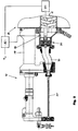
- FIG. 1 shows only a small section of a vacuum sausage filling machine 10.
- the sausage filling machine has in the usual way a feed pump 12 which in the Embodiment a double-spindle pump with spindles (delivery curves) 14, 16 is.
- a feed pump 12 which in the Embodiment a double-spindle pump with spindles (delivery curves) 14, 16 is.
- At the left end of the drawing of the feed pump 12 is located in the drawing Pump outlet 18.
- This ring flange is a clamping nut 24 assigned, with the help of a filling tube or additional devices to the Pump outlet 18 can be connected.
- FIGS. 1 and 2 is using the Ring flange 22 and the clamping nut 24, the housing 32 of a wolf 30 with the Filling machine 10 firmly connected.
- the housing 32 is in the direction of one Center axis 34 is spaced apart from two which are conventional for a wolf and are mounted on the housing Perforated disks 36, 38, between which a conventional rotating cutting knife 40 is fastened on a shaft 42 coaxial to the axis 34.
- a conventional rotating cutting knife 40 is fastened on a shaft 42 coaxial to the axis 34.
- the central axis 34 not only represents the axis of the Wolfes 30, but also the central axis of the spindle 14 of the feed pump 12 so that the wolf 30 with its drive shaft 42 for the cutting knife 40, 44 forms an axial continuation of the spindle 14.
- a connecting shaft 50 By means of a connecting shaft 50, the spindle 14 and the drive shaft 42 of the wolf 30 are rotatably fixed to one another connected.
- the connecting shaft 50 can be designed as a thru axle, the one in a central driver on the end face of the spindle 14 and is inserted into a corresponding driver of the drive shaft 42; the Connecting shaft 50 can also be an integral part of either the spindle 14 or the drive shaft 42.
- the spindle 14 integrally the connecting shaft 50 and the drive shaft 42 includes.
- the position of the axis of rotation is different Feed pump, possibly a gear between pump shaft and drive shaft 42 must be switched, or that a redirection of the flow is required, if pump outlet 18 and wolf 30 one of the preferred embodiment have a different relative position.
- the feed pump 12 conveys through the pump outlet 18 through the shortest route directly into the entrance area 52 of the wolf 30.
- the sausage mass under pressure there is through the two perforated disks 36, 40 are conveyed through and thereby to the desired one Graininess brought.
- the sausage mass then passes through an outlet 54 of the Wolfes 30 in the already mentioned filling tube 20.
- the filling tube 20th has at its right end in the drawing a flange 56 which by means of a further clamping nut 58 firmly connected to the housing 32 of the wolf 30 becomes.
- FIG. 2 differs from that Execution described above only in that here the simple filling pipe 20 a connected via an intermediate tube 70 to the output 54 of the wolf 30 Filling tube 20 'of a portioning device 75, which is conventional and therefore not particularly described with the sausage filling machine 10 is coupled and has no special function within the scope of the present invention. It should therefore only be mentioned that the filling tube 20 'in the usual way for receiving a gathered intestine and the twisting device at the free end of the Filling tube 20 'a conventional casing brake and the required twisting means for twisting successive sausages.
- part of the twist-off device 75 is a spacer element 78, which bridges the space reserved for the wolf 30 and the intermediate pipe 70 is needed.
- FIG. 1 and in Fig. 2 are sketchy for a pressure control necessary elements, namely a pressure sensor 80, a control unit 82 and a drive unit 84 for the feed pump 12 and the cutting set 40, 44.
- the drive unit is mechanically connected to the shaft of the spindle 14.
- the pressure sensor 80 is built into the wall of the housing 32 and measures the pressure in the delivery path between the delivery pump 12 and the cutting set 40, 44.
- the pressure sensor 80 is electrically connected to the control unit 82 and provides the latter with an electrical signal corresponding to the measured pressure Available.
- the control unit 82 the measured pressure is compared with a preset target pressure P target or target pressure interval.
- a corresponding manipulated variable for the drive unit 84 is formed in the control unit 82, for example, a setpoint speed value for a downstream speed controller of the drive or a corresponding control voltage.
- the manipulated variable is transmitted electrically from the control unit 82 to the drive unit 84.
Landscapes
- Life Sciences & Earth Sciences (AREA)
- Engineering & Computer Science (AREA)
- Wood Science & Technology (AREA)
- Zoology (AREA)
- Food Science & Technology (AREA)
- Meat, Egg Or Seafood Products (AREA)
- Processing Of Meat And Fish (AREA)
Description
- Fig. 1
- einen Schnitt durch den Auslaßbereich einer Wurstfüllmaschine und
- Fig. 2
- einen der Fig. 1 ähnlichen Schnitt mit einer am Auslaß der Wurstfüllmaschine angeordneten Abdreheinrichtung.
Claims (15)
- Verfahren zum Herstellen von portionierter Rohwurst, Brühwurst oder dergleichen mit einer vorgebbaren Körnung der Wurstmasse, bei dem das Brät, die Wurstmasse oder dergleichen in eine Füllmaschine gegeben, dort von einer Förderpumpe verdichtet und nach dem Verlassen der Förderpumpe (12) unmittelbar dem Schneidsatz (40, 44) eines Wolfes zugeführt und von diesem auf die gewünschte Endkörnung zerkleinert wird, und bei dem der Antrieb (42, 50, 14) des Schneidsatzes (40, 44) zum Portionieren des Brätes, der Wurstmasse oder dergleichen analog zum Antrieb der Förderpumpe (12) der Füllmaschine (10) unterbrochen wird.
- Verfahren nach Anspruch 1,
bei dem der Druck des Brätes, der Wurstmasse oder dergleichen zwischen Füllmaschine (10) und Schneidsatz (40, 44) zum Regeln der Förderleistung der Füllmaschine (10) gemessen wird. - Vorrichtung zum Herstellen von portionierter Rohwurst, Brühwurst oder dergleichen mit einer vorgebbaren Körnung der Wurstmasse, mit einer von einer Welle getriebenen Förderpumpe, einer die Förderpumpe treibenden Welle und einem Füllrohr, gekennzeichnet durch einen Schneidsatz (40, 44) zwischen dem Auslaß (18) der Förderpumpe (12) und dem Füllrohr (20; 20'), dessen schneidende Elemente mit der die Förderpumpe (12) treibenden Welle (Spindel 14) gekoppelt sind.
- Vorrichtung nach Anspruch 3 mit einer Vakuum-Füllmaschine, deren Förderpumpe eine Doppelspindelpumpe ist, dadurch gekennzeichnet, daß eine (14) der beiden Spindeln (14, 16) an ihrem druckseitigen Ende einen zentralen Wellenansatz aufweist, der durch den Pumpenauslaß (18) hinausragt und an den Schneidsatz (40, 44) angekoppelt ist.
- Vorrichtung nach Anspruch 4,
dadurch gekennzeichnet, daß der Schneidsatz (40, 44) in axialer Fortsetzung der einen Spindel (14) der Förderpumpe (12) angeordnet ist. - Vorrichtung nach einem der Ansprüche 3 bis 5,
gekennzeichnet durch ein Getriebe zwischen dem Schneidsatz (40, 44) und der die Förderpumpe (12) treibenden Welle (Spindel 14). - Vorrichtung nach einem der Ansprüche 3 bis 6,
gekennzeichnet durch einen Drucksensor (80) in der Förderstrecke zwischen Förderpumpe (12) und Schneidsatz (40, 44). - Vorrichtung nach Anspruch 7,
gekennzeichnet durch eine Regelungseinrichtung (82), die die vom Drucksensor erfassten Druckwerte empfangt und den Antrieb (42, 50, 14) der Welle (Spindel 14) so regelt, daß die Druckwerte wärend der Wurstherstellung innerhalb eines vorbestimmten Intervalls liegen. - Vorrichtung nach Anspruch 8,
dadurch gekennzeichnet, daß die Regelungseinrichtung den Antrieb (42, 50, 14) der Welle (Spindel 14) so regelt, daß die Druckwerte wärend der Wurstherstellung innerhalb eines Intervalls zwischen 1 und 20 bar liegen. - Vorrichtung nach Anspruch 9,
dadurch gekennzeichnet, daß die Regelungseinrichtung den Antrieb (42, 50, 14) der Welle (Spindel 14) so regelt, daß die Druckwerte wärend der Wurstherstellung aus Rindfleisch innerhalb eines Intervalls zwischen 15 und 20 bar, wärend der Wurstherstellung aus Schweinefleisch innerhalb eines Intervalls zwischen 11 und 17 bar, und wärend der Wurstherstellung aus Fett innerhalb eines Intervalls zwischen 5 und 8 bar liegen. - Vorrichtung nach einem der Ansprüche 3 bis 10 mit einer Vakuum-Füllmaschine, deren Förderpumpe eine Spindelpumpe ist,
dadurch gekennzeichnet, daß der Wurstmassen-Durchsatz der Schneideelemente bei einer vorgegebenen Druckbeaufschlagung der Wurstmasse am Einlaß (52) der Schneideelemente größer ist, als das Drehvolumen der Förderkurven der Förderpumpe (12). - Vorrichtung nach einem der Ansprüche 3 bis 11,
dadurch gekennzeichnet, daß die Schneideelemente mindestens zwei, in Förderrichtung beabstandete Lochscheiben () aufweisen, vor und/oder hinter denen jeweils mindestens ein Schneidmesser des Schneidsatzes (40, 44) angeordnet ist. - Vorrichtung nach einem der Ansprüche 3 bis 12,
dadurch gekennzeichnet, daß die Förderstrecke zwischen Förderpumpe (12) und Schneidsatz (40, 44) durch einen einerseits an den Auslaß (18) der Förderpumpe (12) und andererseits an den Einlaß (52) der Schneideelemente angeschlossenen Hohlraum mit einem Volumen von ca. 3 bis 8 Litern definiert ist. - Vorrichtung nach Anspruch 13,
dadurch gekennzeichnet, daß der Hohlraum aus mindestens zwei, miteinander koppelbaren Abschnitten gebildet ist. - Vorrichtung nach einem der Ansprüche 14 oder 15,
gekennzeichnet durch ein zwischen dem Auslaß (18) der Förderpumpe (12) und dem Hohlraum und/oder zwischen dem Einlaß (52) der Schneideelemente und dem Hohlraum koppelbarem Zwischenstück.
Applications Claiming Priority (5)
| Application Number | Priority Date | Filing Date | Title |
|---|---|---|---|
| DE19511431 | 1995-03-29 | ||
| DE1995111431 DE19511431A1 (de) | 1995-03-29 | 1995-03-29 | Verfahren und Vorrichtung zum Herstellen von portionierter Rohwurst, Brühwurst o. dgl. |
| DE1995117995 DE19517995A1 (de) | 1995-05-19 | 1995-05-19 | Verfahren und Vorrichtung zum Herstellen von portionierter Wurst |
| DE19517995 | 1995-05-19 | ||
| PCT/EP1996/001390 WO1996029878A1 (de) | 1995-03-29 | 1996-03-29 | Verfahren und vorrichtung zum herstellen von portionierter wurst |
Publications (2)
| Publication Number | Publication Date |
|---|---|
| EP0817570A1 EP0817570A1 (de) | 1998-01-14 |
| EP0817570B1 true EP0817570B1 (de) | 1999-10-20 |
Family
ID=26013839
Family Applications (1)
| Application Number | Title | Priority Date | Filing Date |
|---|---|---|---|
| EP96910943A Expired - Lifetime EP0817570B1 (de) | 1995-03-29 | 1996-03-29 | Verfahren und vorrichtung zum herstellen von portionierter wurst |
Country Status (8)
| Country | Link |
|---|---|
| EP (1) | EP0817570B1 (de) |
| AT (1) | ATE185684T1 (de) |
| BR (1) | BR9607859A (de) |
| CA (1) | CA2216519A1 (de) |
| DE (2) | DE29623020U1 (de) |
| DK (1) | DK0817570T3 (de) |
| ES (1) | ES2141493T3 (de) |
| WO (1) | WO1996029878A1 (de) |
Cited By (1)
| Publication number | Priority date | Publication date | Assignee | Title |
|---|---|---|---|---|
| CN104255892A (zh) * | 2014-09-28 | 2015-01-07 | 纪刚 | 烤肠切花机 |
Families Citing this family (7)
| Publication number | Priority date | Publication date | Assignee | Title |
|---|---|---|---|---|
| DE19642232C2 (de) * | 1996-10-12 | 1999-03-18 | Inofex Fleisch Lebensmitteltec | Zerkleinerungs- und Emulgierautomat |
| DE19830242C2 (de) * | 1998-03-18 | 2000-11-30 | Inofex Fleisch Lebensmitteltec | Zerkleinerungsmaschine, insbesondere für Lebensmittel |
| DE29810004U1 (de) | 1998-06-04 | 1998-08-06 | Wälchli, Hans, Dr., Boppelsen | Fleischwolf am Auslaß einer Wurstfüllmaschine |
| DE19948493C2 (de) * | 1999-10-07 | 2001-10-31 | Rolf Deisenroth | Förder-, Pump- und Schneidsystem für Lebensmittelzerkleinerungsmaschinen, insbesondere für Fleischwölfe |
| DE10248185A1 (de) * | 2002-10-16 | 2004-05-06 | Richard Meyenschein | Fleischereimaschine |
| DE10327672A1 (de) * | 2003-06-20 | 2005-01-20 | Vemag Maschinenbau Gmbh | Vorrichtung und Verfahren zum Fördern und Bearbeiten von pastösen Massen |
| CN104786264B (zh) * | 2014-11-24 | 2019-02-05 | 漯河恒丰机械模具有限责任公司 | 全自动变频切花机 |
Family Cites Families (8)
| Publication number | Priority date | Publication date | Assignee | Title |
|---|---|---|---|---|
| BE670061A (de) * | ||||
| US3036332A (en) * | 1958-09-11 | 1962-05-29 | Townsend Engineering Co | Continuous meat stuffer |
| US2999270A (en) * | 1958-09-29 | 1961-09-12 | Industrial Nucleonics Corp | Extrusion packaging apparatus |
| FR1299087A (fr) * | 1961-06-09 | 1962-07-20 | Appareil automatique pour la confection mécanique de beefsteacks reconstitués | |
| DE1632091A1 (de) * | 1967-04-17 | 1974-04-18 | Alexanderwerk Ag | Wurstfuellmaschine mit foerderschnecken und evakuiereinrichtung |
| US4700899A (en) * | 1985-10-18 | 1987-10-20 | Marlen Research Corporation | Continuous vacuum grinding method and apparatus |
| DE3625191A1 (de) * | 1986-07-25 | 1988-02-04 | Westfaelische Fleischwarenfabr | Einrichtung zum ausstossen einer wurstmasse unter festgelegtem stopfdruck |
| FR2620902B1 (fr) * | 1987-09-29 | 1991-11-29 | Caby Jean & Cie Sarl | Procede de regulation de la masse du produit conditionne dans une enveloppe tubulaire continue |
-
1996
- 1996-03-29 DE DE29623020U patent/DE29623020U1/de not_active Expired - Lifetime
- 1996-03-29 DE DE59603423T patent/DE59603423D1/de not_active Expired - Fee Related
- 1996-03-29 AT AT96910943T patent/ATE185684T1/de active
- 1996-03-29 CA CA002216519A patent/CA2216519A1/en not_active Abandoned
- 1996-03-29 DK DK96910943T patent/DK0817570T3/da active
- 1996-03-29 ES ES96910943T patent/ES2141493T3/es not_active Expired - Lifetime
- 1996-03-29 EP EP96910943A patent/EP0817570B1/de not_active Expired - Lifetime
- 1996-03-29 BR BR9607859-6A patent/BR9607859A/pt not_active Application Discontinuation
- 1996-03-29 WO PCT/EP1996/001390 patent/WO1996029878A1/de not_active Ceased
Cited By (1)
| Publication number | Priority date | Publication date | Assignee | Title |
|---|---|---|---|---|
| CN104255892A (zh) * | 2014-09-28 | 2015-01-07 | 纪刚 | 烤肠切花机 |
Also Published As
| Publication number | Publication date |
|---|---|
| BR9607859A (pt) | 1999-11-30 |
| ES2141493T3 (es) | 2000-03-16 |
| CA2216519A1 (en) | 1996-10-03 |
| EP0817570A1 (de) | 1998-01-14 |
| ATE185684T1 (de) | 1999-11-15 |
| DK0817570T3 (da) | 2000-04-17 |
| DE29623020U1 (de) | 1997-10-30 |
| WO1996029878A1 (de) | 1996-10-03 |
| DE59603423D1 (de) | 1999-11-25 |
Similar Documents
| Publication | Publication Date | Title |
|---|---|---|
| DE2039439C3 (de) | Vorrichtung zur Herstellung einer feststofffreien Fleischmasse | |
| EP2377405A1 (de) | Vorrichtung und Verfahren zum Herstellen und Abfüllen von Feinbrät, insbesondere einer Emulsion | |
| DE69704143T2 (de) | Dosierungsförderschnecke mit mehreren eingeschnittenen Schneckengängen | |
| DE29724045U1 (de) | Mehrfachauslaß-Abgabevorrichtung | |
| EP1738649A1 (de) | Vorrichtung und Verfahren zum Herstellen eines Wurststrangs mit beliebiger geometrischer Aussenkontur | |
| DE29623020U1 (de) | Vorrichtung zum Herstellen von portionierter Wurst | |
| EP1886730B1 (de) | Fleischwolf | |
| DE3038794C2 (de) | Rührwerksmühle | |
| EP1387618A1 (de) | Fleischverarbeitungsmaschine mit fettanalysevorrichtung | |
| DE19517995A1 (de) | Verfahren und Vorrichtung zum Herstellen von portionierter Wurst | |
| DE102009059807A1 (de) | Verfahren zur Herstellung eines Futter- oder Lebensmittels und danach erhaltenes Produkt enthaltend viskoses Gel | |
| EP1447006B1 (de) | Portioniervorrichtung für Nahrungsmittel | |
| DE3542671A1 (de) | Vorrichtung zur feinstzerkleinerung, emulgierung und weiterverarbeitung von fleisch oder dergleichen unter vakuum | |
| DE19511431A1 (de) | Verfahren und Vorrichtung zum Herstellen von portionierter Rohwurst, Brühwurst o. dgl. | |
| WO1999017625A1 (de) | Vorrichtung zum bearbeiten von nahrungs- oder futtermitteln | |
| DE1279415B (de) | Einteilige Messertrommel fuer Haeckselmaschinen | |
| DE3130968A1 (de) | Verfahren und vorrichtung zur kontinuierlichen herstellung von beluefteten zuckermassen | |
| DE2424554C2 (de) | Vorrichtung zur Verarbeitung von ölhaltigen Fruchtkernen | |
| DE102008013806B4 (de) | Portioniervorrichtung (Aufwärts Schneiden) | |
| DE19841289A1 (de) | Vorrichtung zum Fördern und Bearbeiten von Wurstmasse | |
| DD289220A5 (de) | Zufuehrschnecken in fleischwoelfen | |
| DE2034910C3 (de) | Schlagmühle zum Vermahlen von vornehmlich feuchtem oder nassem Fruchtgut | |
| DE69008995T2 (de) | Vorrichtung zum Dosieren und Mahlen. | |
| EP1488702A1 (de) | Vorrrichtung und Verfahren zum Fördern und Bearbeiten von pastösen Massen | |
| EP4613102A1 (de) | Fördervorrichtung und füllmaschine für pastöses lebensmittel, insbesondere fleisch- oder teigwaren |
Legal Events
| Date | Code | Title | Description |
|---|---|---|---|
| PUAI | Public reference made under article 153(3) epc to a published international application that has entered the european phase |
Free format text: ORIGINAL CODE: 0009012 |
|
| 17P | Request for examination filed |
Effective date: 19970904 |
|
| AK | Designated contracting states |
Kind code of ref document: A1 Designated state(s): AT CH DE DK ES FR GB IT LI NL PT |
|
| GRAG | Despatch of communication of intention to grant |
Free format text: ORIGINAL CODE: EPIDOS AGRA |
|
| 17Q | First examination report despatched |
Effective date: 19990128 |
|
| GRAG | Despatch of communication of intention to grant |
Free format text: ORIGINAL CODE: EPIDOS AGRA |
|
| GRAH | Despatch of communication of intention to grant a patent |
Free format text: ORIGINAL CODE: EPIDOS IGRA |
|
| GRAH | Despatch of communication of intention to grant a patent |
Free format text: ORIGINAL CODE: EPIDOS IGRA |
|
| GRAA | (expected) grant |
Free format text: ORIGINAL CODE: 0009210 |
|
| AK | Designated contracting states |
Kind code of ref document: B1 Designated state(s): AT CH DE DK ES FR GB IT LI NL PT |
|
| REF | Corresponds to: |
Ref document number: 185684 Country of ref document: AT Date of ref document: 19991115 Kind code of ref document: T |
|
| REG | Reference to a national code |
Ref country code: CH Ref legal event code: EP |
|
| REG | Reference to a national code |
Ref country code: CH Ref legal event code: NV Representative=s name: PATENTANWAELTE SCHAAD, BALASS, MENZL & PARTNER AG |
|
| REF | Corresponds to: |
Ref document number: 59603423 Country of ref document: DE Date of ref document: 19991125 |
|
| ET | Fr: translation filed | ||
| GBT | Gb: translation of ep patent filed (gb section 77(6)(a)/1977) |
Effective date: 19991119 |
|
| ITF | It: translation for a ep patent filed | ||
| REG | Reference to a national code |
Ref country code: PT Ref legal event code: SC4A Free format text: AVAILABILITY OF NATIONAL TRANSLATION Effective date: 19991029 |
|
| REG | Reference to a national code |
Ref country code: ES Ref legal event code: FG2A Ref document number: 2141493 Country of ref document: ES Kind code of ref document: T3 |
|
| PGFP | Annual fee paid to national office [announced via postgrant information from national office to epo] |
Ref country code: AT Payment date: 20000324 Year of fee payment: 5 |
|
| PGFP | Annual fee paid to national office [announced via postgrant information from national office to epo] |
Ref country code: PT Payment date: 20000327 Year of fee payment: 5 Ref country code: NL Payment date: 20000327 Year of fee payment: 5 Ref country code: CH Payment date: 20000327 Year of fee payment: 5 |
|
| REG | Reference to a national code |
Ref country code: DK Ref legal event code: T3 |
|
| PLBE | No opposition filed within time limit |
Free format text: ORIGINAL CODE: 0009261 |
|
| STAA | Information on the status of an ep patent application or granted ep patent |
Free format text: STATUS: NO OPPOSITION FILED WITHIN TIME LIMIT |
|
| 26N | No opposition filed | ||
| PG25 | Lapsed in a contracting state [announced via postgrant information from national office to epo] |
Ref country code: AT Free format text: LAPSE BECAUSE OF NON-PAYMENT OF DUE FEES Effective date: 20010329 |
|
| PG25 | Lapsed in a contracting state [announced via postgrant information from national office to epo] |
Ref country code: LI Free format text: LAPSE BECAUSE OF NON-PAYMENT OF DUE FEES Effective date: 20010331 Ref country code: CH Free format text: LAPSE BECAUSE OF NON-PAYMENT OF DUE FEES Effective date: 20010331 |
|
| PG25 | Lapsed in a contracting state [announced via postgrant information from national office to epo] |
Ref country code: PT Free format text: LAPSE BECAUSE OF NON-PAYMENT OF DUE FEES Effective date: 20010930 |
|
| PG25 | Lapsed in a contracting state [announced via postgrant information from national office to epo] |
Ref country code: NL Free format text: LAPSE BECAUSE OF NON-PAYMENT OF DUE FEES Effective date: 20011001 |
|
| REG | Reference to a national code |
Ref country code: CH Ref legal event code: PL |
|
| NLV4 | Nl: lapsed or anulled due to non-payment of the annual fee |
Effective date: 20011001 |
|
| REG | Reference to a national code |
Ref country code: GB Ref legal event code: IF02 |
|
| REG | Reference to a national code |
Ref country code: PT Ref legal event code: MM4A Free format text: LAPSE DUE TO NON-PAYMENT OF FEES Effective date: 20010930 |
|
| PGFP | Annual fee paid to national office [announced via postgrant information from national office to epo] |
Ref country code: DE Payment date: 20030502 Year of fee payment: 8 |
|
| PGFP | Annual fee paid to national office [announced via postgrant information from national office to epo] |
Ref country code: GB Payment date: 20030506 Year of fee payment: 8 Ref country code: DK Payment date: 20030506 Year of fee payment: 8 |
|
| PGFP | Annual fee paid to national office [announced via postgrant information from national office to epo] |
Ref country code: ES Payment date: 20030507 Year of fee payment: 8 |
|
| PGFP | Annual fee paid to national office [announced via postgrant information from national office to epo] |
Ref country code: FR Payment date: 20030530 Year of fee payment: 8 |
|
| PG25 | Lapsed in a contracting state [announced via postgrant information from national office to epo] |
Ref country code: GB Free format text: LAPSE BECAUSE OF NON-PAYMENT OF DUE FEES Effective date: 20040329 |
|
| PG25 | Lapsed in a contracting state [announced via postgrant information from national office to epo] |
Ref country code: ES Free format text: LAPSE BECAUSE OF NON-PAYMENT OF DUE FEES Effective date: 20040330 |
|
| PG25 | Lapsed in a contracting state [announced via postgrant information from national office to epo] |
Ref country code: DK Free format text: LAPSE BECAUSE OF NON-PAYMENT OF DUE FEES Effective date: 20040331 |
|
| PG25 | Lapsed in a contracting state [announced via postgrant information from national office to epo] |
Ref country code: DE Free format text: LAPSE BECAUSE OF NON-PAYMENT OF DUE FEES Effective date: 20041001 |
|
| GBPC | Gb: european patent ceased through non-payment of renewal fee |
Effective date: 20040329 |
|
| PG25 | Lapsed in a contracting state [announced via postgrant information from national office to epo] |
Ref country code: FR Free format text: LAPSE BECAUSE OF NON-PAYMENT OF DUE FEES Effective date: 20041130 |
|
| REG | Reference to a national code |
Ref country code: FR Ref legal event code: ST |
|
| PG25 | Lapsed in a contracting state [announced via postgrant information from national office to epo] |
Ref country code: IT Free format text: LAPSE BECAUSE OF NON-PAYMENT OF DUE FEES;WARNING: LAPSES OF ITALIAN PATENTS WITH EFFECTIVE DATE BEFORE 2007 MAY HAVE OCCURRED AT ANY TIME BEFORE 2007. THE CORRECT EFFECTIVE DATE MAY BE DIFFERENT FROM THE ONE RECORDED. Effective date: 20050329 |
|
| REG | Reference to a national code |
Ref country code: ES Ref legal event code: FD2A Effective date: 20040330 |