EP0814301B1 - Befestigungsvorrichtung für eine abgehängte Leuchtenanordnung - Google Patents
Befestigungsvorrichtung für eine abgehängte Leuchtenanordnung Download PDFInfo
- Publication number
- EP0814301B1 EP0814301B1 EP96110066A EP96110066A EP0814301B1 EP 0814301 B1 EP0814301 B1 EP 0814301B1 EP 96110066 A EP96110066 A EP 96110066A EP 96110066 A EP96110066 A EP 96110066A EP 0814301 B1 EP0814301 B1 EP 0814301B1
- Authority
- EP
- European Patent Office
- Prior art keywords
- holder
- fixing device
- locking spring
- bracket
- carrier frame
- Prior art date
- Legal status (The legal status is an assumption and is not a legal conclusion. Google has not performed a legal analysis and makes no representation as to the accuracy of the status listed.)
- Expired - Lifetime
Links
Images
Classifications
-
- F—MECHANICAL ENGINEERING; LIGHTING; HEATING; WEAPONS; BLASTING
- F21—LIGHTING
- F21V—FUNCTIONAL FEATURES OR DETAILS OF LIGHTING DEVICES OR SYSTEMS THEREOF; STRUCTURAL COMBINATIONS OF LIGHTING DEVICES WITH OTHER ARTICLES, NOT OTHERWISE PROVIDED FOR
- F21V21/00—Supporting, suspending, or attaching arrangements for lighting devices; Hand grips
- F21V21/10—Pendants, arms, or standards; Fixing lighting devices to pendants, arms, or standards
- F21V21/112—Fixing lighting devices to pendants
Definitions
- the invention relates to a fastening device for a suspended luminaire arrangement according to the preamble of claim 1.
- Luminaires for interior lighting are called individual luminaires or also strung together directly to light strips arranged below the ceiling or suspended on pendulums.
- a luminaire arrangement be it in the form of a single lamp or one of several Luminaire composite light band, is particularly essential that the lamp assembly to be assembled for Fitter as convenient and easy as possible with one already on the Can be attached to the ceiling of the suspended suspension device.
- a long-known goal is logical a variety of solutions are already known.
- Such a solution is for example in DE-C2-32 14 596 described a suspension device of lights.
- This Example of a known solution was chosen because also in in this case - as is often the case - as a load-bearing component of the luminaire or the luminaire arrangement, a support frame is used.
- a support frame In this example is in the top surface of the support frame, in running longitudinally, a groove with side undercuts admitted.
- the actual Fastening unit as a substantially U-shaped trained suspension spring with angled outwards To use thigh ends. This spring is in the groove used slightly tilted from above, so that their thigh ends reach behind the undercuts of the groove in the support frame.
- Another fastening device is known from DE-U-295 02 571 known for a suspended lamp arrangement, which in connection used with a support frame of the lamp assembly with a longitudinal groove in its top surface with side undercuts is provided.
- the actual mounting unit on the support frame in turn from a U-shaped Suspension spring and a locking plate that can be slipped over its legs.
- the locking plate has a section that corresponds to the cross-sectional shape of the Leg of the suspension spring is adapted. The locking plate is thus slipped over the legs of the suspension spring with play and lies on the top when the luminaire arrangement is installed the mounting rail. Due to the shape of the cutout the locking plate closes a relative movement to a large extent the leg ends of the suspension spring from each other.
- the present invention has for its object to provide a further embodiment for a fastening device of the type mentioned, which is particularly economical to produce due to a simple structural design, allows a time-saving and above all tool-free assembly of a suspended lamp assembly on site and is reliable.
- a fastening device for a suspended lamp arrangement according to the preamble of claim 1 this object is achieved according to the invention by an embodiment which is described by the characterizing features of claim 1.
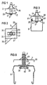
- FIG. 1 and 2 in a side view and in a view from above of the fastening device for a lamp suspended from a ceiling or a Luminaire system in the form of a light strip has a holder for the end of a luminaire suspension in the form of a bolt-shaped connecting element 1, a bearing bracket 2 and a locking spring 3.
- the connecting element 1 the fastening device serves as a transition piece between the shape of the luminaire suspension attached to a ceiling of a pendulum, a chain or a rope to the carrying one Element of the lamp or lighting system.
- this connecting element 1 is this connecting element 1 as a well-known holder for a rope attachment.
- This bolt-shaped holder has a central, conical Drilled hole with side exit hole for receiving a suspension cable, not shown here. This will inserted with its end from above into the connecting element 1, through the exit hole 10 recognizable in FIG. 1 led out to the side and in the conical hole arranged balls held clamped.
- Such holders will be in lighting technology as connecting elements a cable suspension is often used because it is at a distance from a ceiling can be infinitely adjusted on the suspension cable, self-locking under load and tool-free assembly enable. A detailed description of this Connecting element 1 and the representation of a suspended For this reason, rope is no longer required.
- This bearing bracket 2 has in the described embodiment in outline Shape of a parallelogram with a pair of opposing, upward angled side edges 20. The two other parallel sides of the bearing bracket 2 to these angled side edges 20 under a point An angle of 45 °, for example.
- the locking spring 3 is a rectangular leaf spring executed, the mutually parallel narrow sides 30 after are folded down. Parallel to one perpendicular to this Narrow sides 30 extending central axis are two spring tongues 31 cut out and angled upwards. The free Front edges 32 of these spring tongues 31 are approximately semicircular trained trained. The mutual distance of these Front edges 32 of the spring tongues 31 and their approximately semicircular Course are chosen such that the connection element 1 pushed locking spring 3 this cylindrical Connection element 1 only on the two. outer Edge areas of the front edges 32 of the two spring tongues 31 embracing it.
- the spring tongues are preferably 31 in the area of these contact surfaces on the connecting element 1 not ideally pointed, but slightly cut formed so that the spring tongues 31 on the circumference of the connecting element 1 on a total of four diametrically opposed to each other place opposite points like a knife. Adjacent to these end edges 32 of the spring tongues 31 has the locking spring 3 constrictions 33, through the optional that led out laterally from the connecting element 1 Carrier rope end can be guided.
- FIG. 6 A cross-sectional illustration is schematic in FIG shown how this fastening device described above in conjunction with a U-shaped Support frame 6 of a lamp or a light strip used becomes.
- U-shaped profiles for supporting elements Luminaire or a lighting system become conventional frequently used so that it is not necessary here also details of the light or the light strip itself demonstrate.
- the elongated support frame 6 is an upwardly open U-shaped Profile with leg ends flanged inwards 61. These form, among other things, the contact surfaces for the bent Side edges 20 of the bearing bracket 2, which in the Support frame 6 is inserted.
- the locking spring 3 is on the connecting element 1 shown pushed. How else will be shown in detail, the locking spring 3 is relative to the connecting element 1 longitudinally displaceable.
- the locking spring 3 is seated on the cranked leg ends 61 of the support frame and secures the position of the bearing bracket 2 in its system the flanged leg ends 61 of the support frame 6.
- the described Fastening device can also be used Face sides of two adjacent support frames exactly to each other align. In this case, the fastening device to be placed in the middle above the joint of the two day frames.
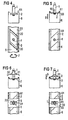
- Figures 4 to 7 is to clarify the function and the assembly of the fastening device described schematically the order of the individual assembly steps in a schematic representation of the fastening device and support frame 6 shown in side and top view.
- the connecting element 1 and the bearing bracket 2 of the fastening device pre-assembled are the minimum width in the form of a parallelogram trained bearing angle 2 selected so that this can be used from above in the U-shaped profile of the support frame 6 is.
- the connecting element can be 1 together with the bearing bracket, as by one Arrow 7 indicated in the profile of the support frame 6 around Turn 90 ° without contact, then the cranked side edges 20 of the bearing bracket 2 parallel to the sides of the Support frame 6 lie.
- an arrow a the final assembly step for the fastener 1,2,3 indicated.
- the locking spring 3 along the Connecting element 1 in the direction of arrow 9 down against the leg ends 61 of the support frame 6 to the plant pushed to these thigh ends.
- the folded ones include Narrow sides 30 of the locking spring 3 these leg ends 61 of the support frame 6.
- the spring tongues 31 below elastic preload. It follows that the front edges 32 of the spring tongues 31 non-positively on the circumference of the connecting element 1 and lock spring 3 in relation automatically locked onto the connecting element 1. This Detent position can only be solved by both spring tongues 31 of the locking spring 3 from the circumference of the connecting element 1 something to be lifted off.
- a support cable can now be inserted in the mounting device thus assembled from above in a conventional manner into the axially extending receiving bore provided in the connecting element 1 and lead out through the exit hole 10.
- this outlet hole 10 is freely accessible laterally in the connecting element 1, so that the suspension cable can also be inserted into the connecting element 1 with the desired length for a predetermined ceiling distance in this application.
- the clamping and locking of the suspension cable in the connecting element 1 is then carried out in a manner familiar to the person skilled in the art, so that further explanations are unnecessary here.
- the fastening device can also first be fixed on the supporting rope and only then connected to the supporting frame 6.
- FIG. 8 a further embodiment for the fastening device and for a correspondingly designed support frame 6 'is now shown in a cross section.
- Continuous row systems are frequently used in lighting technology, in which individual luminaires, arranged one behind the other, are put together to form a closed continuous row.
- the supporting element for such a light band is a support frame 6 ', which in this application is often referred to as a support rail, which extends over the entire length of several lighting units.
- These mounting rails accommodate through-wiring, as well as other mechanical or electrical components of such a light strip. For this purpose, they often have an approximately U-shaped profile which, as in the case of the embodiment in FIG. 8, is often open at the bottom.
Description
Bei einer Befestigungsvorrichtung für eine abgehängte Leuchtenanordnung gemäß dem Oberbegriff des Patentanspruches 1 wird diese Aufgabe erfindungsgemäß durch eine Ausgestaltung gelöst, die durch die kennzeichnenden Merkmale des Patentanspruches 1 beschrieben ist.
In Figur 8 ist nun in einem Querschnitt eine weitere Ausführungsform für die Befestigungsvorrichtung und für einen entsprechend ausgebildeten Tragrahmen 6' gezeigt. In der Beleuchtungstechnik werden häufig Lichtbandsysteme eingesetzt, bei denen Einzelleuchten, hintereinander angeordnet, zu einem geschlossenen Lichtband zusammengesetzt werden. Das tragende Element für ein solches Lichtband bildet ein Tragrahmen 6', der in diesem Anwendungsfall häufig als Tragschiene bezeichnet wird, die sich über die gesamte Länge mehrerer Leuchteneinheiten erstreckt. Diese Tragschienen nehmen eine Durchgangsverdrahtung, auch andere mechanische bzw. elektrische Bauteile eines solchen Lichtbandes auf. Sie besitzen dazu häufig ein annähernd U-förmiges Profil, das häufig, wie im Fall der Ausführungsform von Figur 8, nach unten offen ist.
- senkrecht zur Zeichenebene - auf der einen Seite plan und auf der anderen einer Seite nach unten doppelt abgekröpft ausgebildet ist. Diese Kröpfung ist entsprechend der Tiefe der Befestigungsnut 62 ausgebildet. Der Lagerwinkel 2' kann im übrigen analog zu einer in Figur 2 dargestellten Umrißform als Parallelogramm ausgebildet sein, dann ist er auch in diesem Falle von oben her in die Befestigungsnut 62 einsetzbar und dort durch eine Drehbewegung verriegelbar. Es sind aber auch andere Umrißformen denkbar, die es ermöglichen, ihn mit einer Kippbewegung relativ zur Vertikalen zur Deckfläche des Tragrahmens 6' in die Befestigungsnut 62 einzusetzen. Wesentlich ist auch in diesem Falle, die verriegelte Position des Lagerwinkels 2'durch die in ihrer Form dem Profil des Tragrahmens 6' angepaßte Arretierfeder 3 rastend festzulegen. Während im ersten Ausführungsbeispiel davon ausgegangen wurde, daß die Oberfläche des Verbindungselementes glatt ist, verdeutlicht Figur 8 als Alternative dazu, daß die Oberfläche auch geriffelt ausgebildet sein kann, um gegebenenfalls eine auch formschlüssige Anlage der Federzungen 31 der Arretierfeder 3 am Umfang des Verbindungselementes 1 zu schaffen.
Claims (10)
- Befestigungsvorrichtung für eine abgehängte Leuchtenanordnung mit einer Halterung (1) für das leuchtennahe Ende einer Leuchtenabhängung und einer Befestigungseinheit (2 bzw. 2', 3), die an einem Tragrahmen (6 bzw. 6') der Leuchtenanordnung hinter einander zugekehrten seitlichen Vorsprüngen (61 bzw. 62) im Profil des Tragrahmens lösbar festlegbar ist und die einen Lagerwinkel (2 bzw. 2') umfaßt, auf den die als bolzenförmig ausgebildetes Verbindungselement ausgestaltete Halterung (1) zentrisch aufgesetzt ist, dadurch gekennzeichnet, daß der Lagerwinkel (2; 2') derart an der Halterung (1) festgelegt ist, daß er sich zusammen mit dieser drehen läßt, und daß die Befestigungseinheit eine separate Arretierfeder (3) umfaßt, die als ein Rastelement ausgeführt ist, das eine Einrichtung (30) zum formschlüssigen Angreifen an einem Tragrahmen derart, daß die Arretierfeder (3) gegen eine Drehbewegung relativ zu dem Tragrahmen gesichert ist, und eine Einrichtung (31) zum Angreifen an der Halterung (1) derart, daß diese mitsamt dem Lagerwinkel (2; 2') gegen eine Drehbewegung relativ zu der Arretierfeder (3) gesichert ist, aufweist.
- Befestigungsvorrichtung nach Anspruch 1, dadurch gekennzeichnet, daß die Arretierfeder (3) als ein im wesentlichen flaches Bauteil mit einem Paar von einander parallel gegenüberliegenden, nach unten umgebördelten Seitenkanten (30) zum seitlichen Umgreifen eines Tragrahmens (6; 6') im montierten Zustand von oben und mit einer zentrischen Ausnehmung (31, 32) zum Durchstecken und kraftschlüssigen Sichern der bolzenförmigen Halterung (1) ausgebildet ist.
- Befestigungsvorrichtung nach Anspruch 2, dadurch gekennzeichnet, daß die zentrische Ausnehmung der Arretierfeder (3) als ein Ausschnitt gebildet ist, der zwei mit ihren Stirnkanten (32) einander zugekehrte, an drei Seiten freigeschnittene Federzungen (31) bildet, die nach oben aus der Fläche der Arretierfeder abgebogen sind und sich im montierten Zustand an der bolzenförmigen Halterung (1) unter elastischer Vorspannung abspreizen.
- Befestigungsvorrichtung nach Anspruch 3, dadurch gekennzeichnet, daß die Stirnkanten (32) der Federzungen (30), in Verbindung mit einer Ausbildung der Halterung (1) als ein zylindrischer Bolzen, halbkreisförmig eingezogen derart ausgebildet sind, daß sie sich im montierten Zustand am Umfang der Halterung zangenartig mit messerartig gestalteten Außenecken abstützen.
- Befestigungsvorrichtung nach einem der Ansprüche 1 bis 4, dadurch gekennzeichnet, daß die Oberfläche der Halterung (1) glatt ausgebildet ist.
- Befestigungsvorrichtung nach einem der Ansprüche, 1 bis 4, dadurch gekennzeichnet, daß die Oberfläche der Halterung (1) geriffelt ausgebildet ist.
- Befestigungsvorrichtung nach einem der Ansprüche 1 bis 6, dadurch gekennzeichnet, daß die Halterung (1) als Verbindungselement mit einem Leuchtentragseil ausgebildet ist.
- Befestigungsvorrichtung nach einem der Ansprüche 1 bis 7, dadurch gekennzeichnet, daß der Lagerwinkel (2') aus zwei bezüglich einer Achse parallel zu der Längsachse der Halterung (1) symmetrisch zueinander ausgebildeten Hälften besteht, wobei jede dieser Hälften auf einer Seite jeweils plan ist, so daß sie im montierten Zustand auf der Deckfläche eines Tragrahmens (6') aufliegen kann und auf der anderen Seite jeweils nach unten abgekröpft ist, so daß sie im montierten Zustand eine Hinterschneidung einer Nut (62) eines Tragrahmens hintergreifen kann.
- Befestigungsvorrichtung nach einem der Ansprüche 1 bis 8, dadurch gekennzeichnet, daß der Lagerwinkel (2) im Umriß als ein Parallelogramm ausgebildet ist, bei dem der Abstand eines der beiden Seitenpaare größer als der des anderen Seitenpaares ist.
- Befestigungsvorrichtung nach Anspruch 9, dadurch gekennzeichnet, daß der Lagerwinkel (2) nach oben abgekantete Seitenkanten (20) aufweist.
Priority Applications (3)
| Application Number | Priority Date | Filing Date | Title |
|---|---|---|---|
| EP96110066A EP0814301B1 (de) | 1996-06-21 | 1996-06-21 | Befestigungsvorrichtung für eine abgehängte Leuchtenanordnung |
| AT96110066T ATE247254T1 (de) | 1996-06-21 | 1996-06-21 | Befestigungsvorrichtung für eine abgehängte leuchtenanordnung |
| DE59610660T DE59610660D1 (de) | 1996-06-21 | 1996-06-21 | Befestigungsvorrichtung für eine abgehängte Leuchtenanordnung |
Applications Claiming Priority (1)
| Application Number | Priority Date | Filing Date | Title |
|---|---|---|---|
| EP96110066A EP0814301B1 (de) | 1996-06-21 | 1996-06-21 | Befestigungsvorrichtung für eine abgehängte Leuchtenanordnung |
Publications (2)
| Publication Number | Publication Date |
|---|---|
| EP0814301A1 EP0814301A1 (de) | 1997-12-29 |
| EP0814301B1 true EP0814301B1 (de) | 2003-08-13 |
Family
ID=8222919
Family Applications (1)
| Application Number | Title | Priority Date | Filing Date |
|---|---|---|---|
| EP96110066A Expired - Lifetime EP0814301B1 (de) | 1996-06-21 | 1996-06-21 | Befestigungsvorrichtung für eine abgehängte Leuchtenanordnung |
Country Status (3)
| Country | Link |
|---|---|
| EP (1) | EP0814301B1 (de) |
| AT (1) | ATE247254T1 (de) |
| DE (1) | DE59610660D1 (de) |
Family Cites Families (2)
| Publication number | Priority date | Publication date | Assignee | Title |
|---|---|---|---|---|
| DE8801685U1 (de) * | 1988-02-10 | 1989-03-09 | Licentia Patent-Verwaltungs-Gmbh, 6000 Frankfurt, De | |
| DE9312876U1 (de) * | 1993-08-27 | 1993-10-28 | Ellenbeck Gerd | Vorrichtung zur hängenden Befestigung von Tragschienen an Bauteilen |
-
1996
- 1996-06-21 DE DE59610660T patent/DE59610660D1/de not_active Expired - Fee Related
- 1996-06-21 EP EP96110066A patent/EP0814301B1/de not_active Expired - Lifetime
- 1996-06-21 AT AT96110066T patent/ATE247254T1/de not_active IP Right Cessation
Also Published As
| Publication number | Publication date |
|---|---|
| ATE247254T1 (de) | 2003-08-15 |
| DE59610660D1 (de) | 2003-09-18 |
| EP0814301A1 (de) | 1997-12-29 |
Similar Documents
| Publication | Publication Date | Title |
|---|---|---|
| EP1070923B1 (de) | Vorrichtung zur Befestigung von Solarmodulen | |
| DE2125637A1 (de) | Gitterförmige Rasterkonstruktion für abgehängte Decken | |
| EP2171817B1 (de) | Vorrichtung zum anordnen und befestigen von elektrischen einheiten insbesondere in einem schaltschrank, sowie ein montagesystem mit einer solchen vorrichtung | |
| AT15184U1 (de) | Lichtbandsystem mit länglicher Tragschiene | |
| DE102011083993B4 (de) | Lichtband | |
| EP0621444A1 (de) | Schnellverschluss für Leuchteneinsätze | |
| DE2946622C2 (de) | Vorrichtung zum Befestigen von Gegenständen an einer Profilschiene mit in entgegengesetzten Richtungen auswärts abstehenden Flanschen | |
| DE3841179A1 (de) | Befestigungsvorrichtung fuer plattenfoermige wand- oder deckenelemente | |
| EP0621439B1 (de) | Lichtbandanordnung | |
| DE60301931T2 (de) | Verbesserte Trageeinrichtung für Drahtgitterkanal mit Schnellkupplung | |
| EP0814301B1 (de) | Befestigungsvorrichtung für eine abgehängte Leuchtenanordnung | |
| EP1026415A2 (de) | Befestigungsvorrichtung | |
| AT403839B (de) | Halter insbesondere für rohre, kabelstränge und hohlleiter | |
| EP0947765B1 (de) | Vorrichtung zum Befestigen einer Deckeneinbauleuchte | |
| DE102018105970B4 (de) | Variable Deckenbefestigung | |
| EP1114935A2 (de) | Knotenverbinder zum Befestigen einer Montageschiene auf Stoss an einer anderen Montageschiene | |
| EP0912860B1 (de) | Einbauleuchte mit haltemitteln zu ihrer halterung in einem einbaukörper oder haltemittel für eine solche einbauleuchte | |
| EP0268283B1 (de) | Deckeneinbauleuchte | |
| EP0040180A1 (de) | Montagegestell | |
| AT410234B (de) | Vorrichtung zum abhängen von decken | |
| EP1148292B1 (de) | Haltevorrichtung für Deckeneinbauleuchten | |
| DE3907755C2 (de) | ||
| EP1028205A2 (de) | Halterung für die seitlichen Führungsschienen einer Wintergartenmarkise | |
| DE19713818A1 (de) | Adapter für ein Haltemittel, welches zum Befestigen einer Einbauleuchte in einer Einbauöffnung bestimmt ist, oder Haltemittel oder Einbauleuchte mit einem solchen Adapter | |
| DE1913393A1 (de) | Aufhaengevorrichtung fuer Beleuchtungskoerper |
Legal Events
| Date | Code | Title | Description |
|---|---|---|---|
| PUAI | Public reference made under article 153(3) epc to a published international application that has entered the european phase |
Free format text: ORIGINAL CODE: 0009012 |
|
| AK | Designated contracting states |
Kind code of ref document: A1 Designated state(s): AT CH DE IT LI NL |
|
| RBV | Designated contracting states (corrected) |
Designated state(s): AT CH DE IT LI NL |
|
| 17P | Request for examination filed |
Effective date: 19980626 |
|
| RAP1 | Party data changed (applicant data changed or rights of an application transferred) |
Owner name: SITECO BELEUCHTUNGSTECHNIK GMBH |
|
| 17Q | First examination report despatched |
Effective date: 20010124 |
|
| GRAH | Despatch of communication of intention to grant a patent |
Free format text: ORIGINAL CODE: EPIDOS IGRA |
|
| GRAH | Despatch of communication of intention to grant a patent |
Free format text: ORIGINAL CODE: EPIDOS IGRA |
|
| GRAA | (expected) grant |
Free format text: ORIGINAL CODE: 0009210 |
|
| AK | Designated contracting states |
Designated state(s): AT CH DE IT LI NL |
|
| REG | Reference to a national code |
Ref country code: CH Ref legal event code: EP |
|
| REG | Reference to a national code |
Ref country code: CH Ref legal event code: NV Representative=s name: ING. HANS LUDESCHER, PATENTABTEILUNG DER SFS GRUPP |
|
| REF | Corresponds to: |
Ref document number: 59610660 Country of ref document: DE Date of ref document: 20030918 Kind code of ref document: P |
|
| PLBE | No opposition filed within time limit |
Free format text: ORIGINAL CODE: 0009261 |
|
| STAA | Information on the status of an ep patent application or granted ep patent |
Free format text: STATUS: NO OPPOSITION FILED WITHIN TIME LIMIT |
|
| 26N | No opposition filed |
Effective date: 20040514 |
|
| REG | Reference to a national code |
Ref country code: CH Ref legal event code: PCAR Free format text: ISLER & PEDRAZZINI AG;POSTFACH 1772;8027 ZUERICH (CH) |
|
| PGFP | Annual fee paid to national office [announced via postgrant information from national office to epo] |
Ref country code: AT Payment date: 20080612 Year of fee payment: 13 |
|
| PGFP | Annual fee paid to national office [announced via postgrant information from national office to epo] |
Ref country code: IT Payment date: 20080626 Year of fee payment: 13 |
|
| PGFP | Annual fee paid to national office [announced via postgrant information from national office to epo] |
Ref country code: NL Payment date: 20080603 Year of fee payment: 13 Ref country code: DE Payment date: 20080612 Year of fee payment: 13 Ref country code: CH Payment date: 20080710 Year of fee payment: 13 |
|
| REG | Reference to a national code |
Ref country code: CH Ref legal event code: PL |
|
| NLV4 | Nl: lapsed or anulled due to non-payment of the annual fee |
Effective date: 20100101 |
|
| PG25 | Lapsed in a contracting state [announced via postgrant information from national office to epo] |
Ref country code: LI Free format text: LAPSE BECAUSE OF NON-PAYMENT OF DUE FEES Effective date: 20090630 Ref country code: CH Free format text: LAPSE BECAUSE OF NON-PAYMENT OF DUE FEES Effective date: 20090630 |
|
| PG25 | Lapsed in a contracting state [announced via postgrant information from national office to epo] |
Ref country code: DE Free format text: LAPSE BECAUSE OF NON-PAYMENT OF DUE FEES Effective date: 20100101 Ref country code: AT Free format text: LAPSE BECAUSE OF NON-PAYMENT OF DUE FEES Effective date: 20090621 |
|
| PG25 | Lapsed in a contracting state [announced via postgrant information from national office to epo] |
Ref country code: NL Free format text: LAPSE BECAUSE OF NON-PAYMENT OF DUE FEES Effective date: 20100101 |
|
| PG25 | Lapsed in a contracting state [announced via postgrant information from national office to epo] |
Ref country code: IT Free format text: LAPSE BECAUSE OF NON-PAYMENT OF DUE FEES Effective date: 20090621 |