EP0813656B1 - Commande de vanne - Google Patents
Commande de vanne Download PDFInfo
- Publication number
- EP0813656B1 EP0813656B1 EP96906570A EP96906570A EP0813656B1 EP 0813656 B1 EP0813656 B1 EP 0813656B1 EP 96906570 A EP96906570 A EP 96906570A EP 96906570 A EP96906570 A EP 96906570A EP 0813656 B1 EP0813656 B1 EP 0813656B1
- Authority
- EP
- European Patent Office
- Prior art keywords
- valve
- conduit
- source
- pressure
- reduced pressure
- Prior art date
- Legal status (The legal status is an assumption and is not a legal conclusion. Google has not performed a legal analysis and makes no representation as to the accuracy of the status listed.)
- Expired - Lifetime
Links
Images
Classifications
-
- F—MECHANICAL ENGINEERING; LIGHTING; HEATING; WEAPONS; BLASTING
- F15—FLUID-PRESSURE ACTUATORS; HYDRAULICS OR PNEUMATICS IN GENERAL
- F15C—FLUID-CIRCUIT ELEMENTS PREDOMINANTLY USED FOR COMPUTING OR CONTROL PURPOSES
- F15C3/00—Circuit elements having moving parts
- F15C3/04—Circuit elements having moving parts using diaphragms
-
- F—MECHANICAL ENGINEERING; LIGHTING; HEATING; WEAPONS; BLASTING
- F15—FLUID-PRESSURE ACTUATORS; HYDRAULICS OR PNEUMATICS IN GENERAL
- F15C—FLUID-CIRCUIT ELEMENTS PREDOMINANTLY USED FOR COMPUTING OR CONTROL PURPOSES
- F15C5/00—Manufacture of fluid circuit elements; Manufacture of assemblages of such elements integrated circuits
-
- Y—GENERAL TAGGING OF NEW TECHNOLOGICAL DEVELOPMENTS; GENERAL TAGGING OF CROSS-SECTIONAL TECHNOLOGIES SPANNING OVER SEVERAL SECTIONS OF THE IPC; TECHNICAL SUBJECTS COVERED BY FORMER USPC CROSS-REFERENCE ART COLLECTIONS [XRACs] AND DIGESTS
- Y10—TECHNICAL SUBJECTS COVERED BY FORMER USPC
- Y10S—TECHNICAL SUBJECTS COVERED BY FORMER USPC CROSS-REFERENCE ART COLLECTIONS [XRACs] AND DIGESTS
- Y10S137/00—Fluid handling
- Y10S137/907—Vacuum-actuated valves
-
- Y—GENERAL TAGGING OF NEW TECHNOLOGICAL DEVELOPMENTS; GENERAL TAGGING OF CROSS-SECTIONAL TECHNOLOGIES SPANNING OVER SEVERAL SECTIONS OF THE IPC; TECHNICAL SUBJECTS COVERED BY FORMER USPC CROSS-REFERENCE ART COLLECTIONS [XRACs] AND DIGESTS
- Y10—TECHNICAL SUBJECTS COVERED BY FORMER USPC
- Y10T—TECHNICAL SUBJECTS COVERED BY FORMER US CLASSIFICATION
- Y10T137/00—Fluid handling
- Y10T137/0318—Processes
-
- Y—GENERAL TAGGING OF NEW TECHNOLOGICAL DEVELOPMENTS; GENERAL TAGGING OF CROSS-SECTIONAL TECHNOLOGIES SPANNING OVER SEVERAL SECTIONS OF THE IPC; TECHNICAL SUBJECTS COVERED BY FORMER USPC CROSS-REFERENCE ART COLLECTIONS [XRACs] AND DIGESTS
- Y10—TECHNICAL SUBJECTS COVERED BY FORMER USPC
- Y10T—TECHNICAL SUBJECTS COVERED BY FORMER US CLASSIFICATION
- Y10T137/00—Fluid handling
- Y10T137/8593—Systems
- Y10T137/87249—Multiple inlet with multiple outlet
-
- Y—GENERAL TAGGING OF NEW TECHNOLOGICAL DEVELOPMENTS; GENERAL TAGGING OF CROSS-SECTIONAL TECHNOLOGIES SPANNING OVER SEVERAL SECTIONS OF THE IPC; TECHNICAL SUBJECTS COVERED BY FORMER USPC CROSS-REFERENCE ART COLLECTIONS [XRACs] AND DIGESTS
- Y10—TECHNICAL SUBJECTS COVERED BY FORMER USPC
- Y10T—TECHNICAL SUBJECTS COVERED BY FORMER US CLASSIFICATION
- Y10T137/00—Fluid handling
- Y10T137/8593—Systems
- Y10T137/877—With flow control means for branched passages
- Y10T137/87708—With common valve operator
- Y10T137/87716—For valve having a flexible diaphragm valving member
Definitions
- Embodiments of the present invention relate generally to controlling a valve. Specifically, embodiments described herein relate to a valve control and a method for controlling a valve, or an array of valves.
- a pneumatically actuated and controlled valve may be used in a valve array comprising multiple valves.
- the position of each valve i.e. open or closed, may be changed by applying a relatively reduced pressure or a relatively increased pressure, respectively, to the valve.
- each valve is operatively connected with its own control valve which may be a relatively expensive solenoid valve.
- two valves are needed to perform a certain task, one to perform the task and one to control the valve performing the task. This arrangement may be bulky and costly to manufacture and to use. Thus, it is desirable to have an improved way of controlling a valve.
- a given control valve such as a solenoid valve
- a control valve may be "shared” or used by a number of other valves through a network. Sharing of valves may result in cost savings, size and weight reductions, and/or reduction in complexity of the overall design of the valve array and its associated control structure.
- US-A-3 540 477 and US-A-3 837 615 describe a valve control according to the preamble of claim 1.
- One embodiment provides a valve control comprising a first valve fluidly connected with a first fluid conveying conduit and a second fluid conveying conduit.
- the first valve is movable between a first position where fluid communicates between the first fluid conveying conduit and the second fluid conveying conduit and a second position where fluid does not communicate between the first fluid conveying conduit and the second fluid conveying conduit.
- a first source of relatively increased pressure and a first source of relatively reduced pressure are provided.
- a third conduit fluidly connects the first source of relatively increased pressure and the first source of relatively reduced pressure with the first valve.
- a third valve is fluidly connected with the third conduit.
- the third valve is movable between a first position where the first source of relatively increased pressure is fluidly connected with the third conduit and the first valve thereby moving the first valve toward its second position and a second position where the first source of relatively reduced pressure is fluidly connected with the third conduit and the first valve thereby moving the first valve toward its first position.
- a second valve is fluidly connected with the third conduit between the third valve and the first valve. The second valve is movable between a first position where fluid communicates between the first valve and the third valve and a second position where no fluid communicates between the first valve and the third valve, irrespective of the position of said third valve.
- a first valve is fluidly connected with a first fluid conveying conduit and a second fluid conveying conduit.
- the first valve is moved between a first position where fluid communicates between the first fluid conveying conduit and the second fluid conveying conduit and a second position where fluid does not communicate between the first fluid conveying conduit and the second fluid conveying conduit.
- a first source of relatively increased pressure and a first source of relatively reduced pressure are fluidly connected with the first valve by a third conduit.
- a third valve is fluidly connected to the third conduit.
- the third valve is moved between a first position where the first source of relatively increased pressure is fluidly connected with the third conduit and the first valve thereby moving the first valve toward its second position and a second position where the first source of relatively reduced pressure is fluidly connected with the third conduit and the first valve thereby moving the first valve toward its first position.
- a second valve is fluidly connected with the third conduit between the third valve and the first valve. The second valve is moved between a first position where fluid communicates between the first valve and the third valve and a second position where no fluid communicates between the first valve and the third valve, irrespective of the position of said third valve.
- a valve control comprising a first valve fluidly connected with a first fluid conveying conduit and a second fluid conveying conduit.
- the first valve is movable between a first position where fluid communicates between the first fluid conveying conduit and the second fluid conveying conduit and a second position where no fluid communicates between the first fluid conveying conduit and the second fluid conveying conduit.
- a memory conduit is fluidly connected with the first valve for maintaining the first valve in the first position or the second position.
- a second valve is fluidly connected with the first valve and the memory conduit for either moving the first valve between the first position and the second position or for maintaining a pressure state of the memory conduit for keeping the first valve in either the first position or the second position depending upon the pressure state of the memory conduit.
- a first valve is fluidly connected with a first fluid conveying conduit and a second fluid conveying conduit.
- the first valve moves between a first position where fluid communicates between the first fluid conveying conduit and the second fluid conveying conduit and a second position where no fluid communicates between the first fluid conveying conduit and the second fluid conveying conduit.
- a second valve is fluidly connected with the first valve.
- a memory conduit is fluidly connected fluidly between the first valve and the second valve for maintaining the first valve in the first position or the second position.
- the second valve is moved to move the first valve between the first position and the second position.
- the second valve is moved to maintain a pressure state of the memory conduit for keeping the first valve in either the first position or the second position depending upon the pressure state of the memory conduit.
- the method of the invention also provides a number of first valves.
- Each of the number of first valves is fluidly connected with a first fluid conveying conduit and a second fluid conveying conduit.
- Each of the first valves is movable between a first position where fluid communicates between the first fluid conveying conduit and the second fluid conveying conduit and a second position where no fluid communicates between the first fluid conveying conduit and the second fluid conveying conduit.
- At least one second valve is fluidly connected with each of the number of first valves with at least one memory conduit.
- a source of relatively increased pressure or relatively reduced pressure is fluidly connected with the at least one second valve.
- the at least one second valve is movable between a first position where the source of relatively increased pressure or relatively reduced pressure is fluidly connected with the at least one memory conduit and a second position where the source of relatively increased pressure or relatively reduced pressure is not fluidly connected with the at least one memory conduit.
- the at least one second valve is moved toward its first position to fluidly connect the at least one memory conduit and a first subset of the number of first valves with the source of relatively increased pressure or relatively reduced pressure and to move the first subset of the number of first valves toward a first predetermined one of its first position and its second position responsive to the relatively increased pressure or the relatively reduced pressure.
- the at least one second valve is moved toward its second position thereby maintaining the first subset of the number of first valves in the first predetermined one of its first position and its second position.
- the source of relatively increased pressure or relatively reduced pressure is fluidly connected with a second subset of the number of first valves to move the second subset of the number of first valves toward a second predetermined one of its first position and its second position responsive to the relatively increased pressure or the relatively reduced pressure.
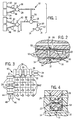
- Fig. 1 generally illustrates an embodiment 10 and a method for controlling a first valve 12.
- the embodiment 10 and method are initially disclosed herein with respect to controlling only the first valve 12.
- the embodiment 10 and method may be used, with suitable modifications, to control a desired number of valves.
- the embodiment 10 is discussed with respect to a particular valve construction, illustrated in Fig. 2.
- Other constructions of the embodiment 10, such as that illustrated in Fig. 4 comprising an insert valve, are also possible.
- the embodiment 10 may be used, again with suitable modifications, to control valves of any appropriate construction.
- a valve may be controlled fluidly, electrostatically, electromagnetically, mechanically or the like.
- first valve 12 and other valves may be a flow through valve fluidly connected with a fluid conveying conduit. Flow through valves are discussed, for instance, in US-A-5 542 444 filed on November 7, 1994 and assigned to the assignee of the present case. The entire disclosure of that copending patent application is incorporated herein by reference. Accordingly, the first fluid conveying conduit 14 and the second fluid conveying conduit 16 may be portions of the same fluid conveying conduit.
- the first valve 12 is fluidly connected between a first fluid conveying conduit 14 and a second fluid conveying conduit 16 such that operation of the first valve 12 determines whether or not fluid communicates between conduits 14 and 16. Specifically, when the first valve 12 is in a first position, fluid communicates between conduits 14 and 16, and when the first valve 12 is in a second position, fluid does not communicate between the conduits 14 and 16. Any desired fluid, such as gasses, liquids and the like, may be present in conduits 14 and 16.
- the first valve 12 is fluidly connected to a second valve 18 by a control or memory conduit 20. In some embodiments, there may be multiple second valves 18 fluidly connected with a single first valve 12.
- control conduit 20 may be understood to be a memory conduit in that the pressure maintained in the memory conduit 20 maintains the first valve 12 in either the first position or the second position, i.e. the memory conduit 20 "remembers" the last pressure state applied to or the last position of the first valve 12.
- the pressure state of the memory conduit 20 determines the position of the first valve 12.
- Operation of the second valve 18 determines pressure in the control conduit 20. Specifically, when the second valve 18 is in a first position, a third conduit 22 is fluidly connected with the control conduit 20 such that pressure in the third conduit 22 is exposed to the control conduit 20. When the second valve 18 is in a second position, the third conduit 22 does not fluidly communicate with the control conduit 20 and the pressure in the control conduit 20 is independent of or isolated from the pressure in the third conduit 22.
- the second valve 18 is fluidly connected by the third conduit 22 to a third valve 24 and is fluidly connected by a fourth conduit 26 to a fourth valve 28. Pressure within the fourth conduit 26 controls operation of the second valve 18.
- the second valve 18 may be maintained in either the first or second position by mechanical means, such as a spring and the like. In these embodiments, one of the pressure sources may not be needed and therefore it and associated structures may be eliminated. In any case, operation of the second valve 18 determines whether or not the control conduit 20 communicates fluidicly with the third conduit 22.
- the fluid present in the control conduit 20 is a gas such as air and the like.
- the fourth valve 28 is fluidly connected with a source 30 of relatively reduced pressure by a fifth conduit 32 and is fluidly connected with a source 34 of relatively increased pressure by a sixth conduit 36.
- the fourth valve 28 is operatively coupled with a controller, not shown, by connector 38, which may convey to the fourth valve 28 any suitable signal, such as an electronic signal, a fluidic or pneumatic signal and the like, for controlling operation of the fourth valve 28.
- Operation of the fourth valve 28 determines whether the source 30 or the source 34 is fluidly connected with the fourth conduit 26. When in a first position, the fourth valve 28 fluidly connects the sixth conduit 36 with the fourth conduit 26. In a second position, the fourth valve 28 fluidly connects the fifth conduit 32 with the fourth conduit 26.
- the source 30 provides a relatively reduced pressure that is approximately less than ambient pressure whereas the source 34 provides a relatively increased pressure which is approximately more than ambient pressure.
- the pressures provided by the sources 30 and 34 are predetermined for operating the second valve 18. In one embodiment, the pressure provided by source 34 is approximately more than the highest pressure expected to be present at any time in the control conduit 20 or the third conduit 22. Likewise, the pressure provided by source 30 is approximately less than the pressure expected at any time to be present in conduits 20 or 22.
- the source 30 provides a relatively reduced pressure of about 67728 Pa (20 inches of mercury) and the source 34 provides a relatively increased pressure of about 137895 Pa (20 psig.)
- the sources 30 and 34 may be integrated, such as in the form of a variable pressure source, e.g. a regulator, piston pump, and the like, which provide a relatively increased pressure or a relatively reduced pressure, as desired.
- the fourth valve 28 and sources 30 and 34 may be eliminated.
- the third valve 24 is operatively coupled with a controller, which is not shown, but may be the same as or substantially similar to the first-mentioned controller, by connector 40, which may convey to the third valve 24 any suitable signal, such as an electronic signal, a pneumatic signal and the like, for controlling operation of the third valve 24.
- the connectors 38 and 40 may be replaced by mechanical actuators which operate the respective valves 24 and 28.
- the third and fourth valves 24 and 28, respectively may be electrically actuated, e.g. a solenoid valve, or mechanically actuated, e.g. by a spring.
- the third valve 24 fluidly connects the third conduit 22 with either a seventh conduit 42 or an eighth conduit 44.
- the seventh conduit 42 fluidly connects the third valve 24 with a source 46 of relatively reduced pressure and the eighth conduit 44 fluidly connects the third valve 24 with a source 48 of relatively increased pressure.
- the third valve 24 fluidly connects the eighth conduit 44 with the third conduit 22.
- the third valve 24 fluidly connects the seventh conduit 42 with the third conduit 22.
- the source 46 provides a pressure which is approximately less than ambient pressure and the source 48 provides a pressure which is approximately more than ambient pressure.
- the pressures provided by the sources 46 and 48 are predetermined for operating the first valve 12. In a specific embodiment, the pressure provided by the source 48 is approximately more than the highest pressure expected to be present at any time in conduits 14 or 16 and the pressure provided by source 46 is approximately less than the pressure expected to be present at any time in conduits 14 or 16.
- the source 46 provides a relatively reduced pressure of about 50796 Pa (15 inches of mercury) and the source 48 provides a relatively increased pressure of about 103421 Pa (15 psig.)
- the sources 46 and 48 may be integrated, such as in the form of a variable pressure source, e.g. a regulator, piston pump, and the like. In these embodiments, the third valve 24 and sources 46 and 48 may be eliminated.
- the absolute pressure i.e. pressure value with respect to vacuum
- the absolute pressure provided by source 34 is approximately more than the absolute pressure provided by source 48.
- the absolute pressure provided by source 48 is approximately more than the highest pressure expected at any time to be present in conduits 14 and 16.
- the absolute pressure provided by source 30 is approximately lower than the absolute pressure provided by source 46.
- the absolute pressure provided by source 46 is approximately less than the lowest pressure expected at any time to be present in conduits 14 and 16.
- Pressure differentials exist among the sources 30, 34, 46 and 48 and the conduits 14 and 16. These pressure differentials assist in intended operation of the embodiment 10.
- the embodiment 10 may be used with a membrane valve shown in Fig. 2.
- the membrane valve may be constructed by forming channels or conduits and spaces in a block 50 of material, such as a polymer and the like.
- the valve comprises a flexible member 52 which moves within the spaces formed in the block 50 responsive to a pressure exposed to the flexible member 52. More than one block 50 and more than one flexible member 52 may be used. For instance, a flexible member 52 may be placed between two blocks 50.
- conduits 14 and 16 are fluidly connected with a volume 54 bounded by a first recessed surface 56 and the flexible member 52.
- a side of the flexible member 52 opposite to the side thereof facing the first recessed surface 56 faces a second recessed surface 58.
- the control conduit 20 terminates at the second recessed surface 58 such that pressure present in the control conduit 20 is exposed to the flexible member 52.
- the flexible member 52 is moved toward the second recessed surface 58 thereby allowing fluid communication between conduits 14 and 16 through the volume 54.
- the pressure in the control conduit 20 is approximately more than the pressure present in both conduits 14 and 16
- the flexible member is moved toward the first recessed surface 56. With the flexible member 52 in this position, fluid communication between the conduits 14 and 16 is interrupted or limited.
- the appropriate pressure is first applied to the third conduit 22 by operating the third valve 24. For example, if it is desired to close the valve 12, the relatively increased pressure from source 48 is applied to the third conduit 22. In subsequent operations this will enable the first valve 12 to move into the second or closed position where there is no fluid communication between conduits 14 and 16. If it is desired to open the valve 12, the relatively reduced pressure from source 46 is applied to the third conduit 22. In subsequent operations this will enable the first valve 12 to move into the first or open position where there is fluid communication between conduits 14 and 16.
- the fourth valve 28 may be operated first so as to enable conduit 22 to be fluidicly connected to memory conduit 20, followed by the actuation of valve 24 to select the pressure state to be present in the memory conduit.
- the pressure state originally present in conduit 22 should match the pressure state of the memory conduit 20 to prevent unintentional changing of the position of valve 12.
- the pressure now present in the control conduit 20 determines the position of the first valve 12 as determined by the pressure applied to the third conduit 22, which, in turn, is determined by the position of the third valve 24.
- the fourth valve 28 may be moved toward its first position. Moving the fourth valve 28 toward its first position fluidly connects the source 34 of relatively increased pressure to the fourth conduit 26 through the sixth conduit 36 and the fourth valve 28. Application of the relatively increased pressure from source 34 moves the flexible member 52 toward the first recessed surface 56 of the second valve 18. Fluid communication between the third conduit 22 and the control conduit 20 is interrupted or reduced. With the second valve 18 in this position, the control conduit 20, whose pressure was equal to the pressure present in the third conduit 22, is fluidly isolated. The first valve 12 remains in its desired position irrespective of further changes of the pressure, caused by operation of the third valve 24, in the third conduit 22.
- the valve 18 Since the second valve 18 holds or maintains a pressure condition in the control conduit 20 and thereby holds or maintains the position of the first valve 12, the valve 18 may be referred to as a "latch valve.” Since moving or changing the position of the second valve 18 depends upon operation of the fourth valve 28, the fourth valve 28 may be referred to as an "enable valve” and the fourth conduit 26 may be referred to as an "enable line.” Since, the third valve 24 determines the position to which the first valve 12 changes or moves, when the second valve 18 is open or enabled, the third valve 24 may be referred to as a "data valve” and the third conduit 22 may be referred to as the "data line.” These terms are used to describe an exemplary embodiment 60 illustrated in Fig. 3 which is provided to facilitate understanding only.
- the enable valves 28 and the data valves 24 may be, in one embodiment, electrically powered solenoid valves. In a particular embodiment, the solenoid valves are Lee Valve Model LHDX0501650A (Westbrook, CT).
- sixteen valve pairs 62 are illustrated. Each valve pair comprises a first valve 12 and a second valve 18 and a memory conduit 20 between them superimposed on each other and collectively labeled 62. Multiple valve pairs 62 share a solenoid valve. In the illustrated embodiment, the sixteen valve pairs 62 are arranged in a matrix fashion, with their enable lines 26 fluidly connected to four enable valves 28 (solenoid valves in this embodiment) and their data lines 22 fluidly connected to four data valves 24 (solenoid valves in this embodiment). Fewer solenoid valves are required to control the array of first valves 12, thereby possibly producing a less expensive valve array control structure.
- valve pairs 62 in the leftmost "column", as viewed, may be operated by moving the data valves 24 to the desired valve 24 positions. Then, the leftmost, as viewed, enable valve 28 is actuated, so that only the first valves 12 associated with the leftmost valve pairs move toward the positions determined by the four data valves 24.
- a similar procedure may be used for each column of valve pairs 62, thereby producing any desired valve alignment. In this configuration, a total of four enable valves and four data valves, 28 and 24, respectively, control sixteen valve pairs 62. In a five by five configuration, a total of five enable valves and five data valves, 28 and 24, control twenty-five valve pairs 62.
- valves 12 To change the position of a desired number of valves that is less than the total number of valve pairs 62, only some of the columns may need to be operated. It is possible to group the individual valves in columns to perform a particular application with a reduced number of valve operations. In order to provide more favorable groupings or arrangements of valves, more than one second valve 18 may be operatively or fluidly associated with a particular first valve 12. It is also possible to fluidly associate more than one first valve 12 with a particular second valve 18, if all first valves 12 so associated always operate conjointly or in tandem.
- Maintenance of the position of the first valve 12 is due to the maintenance of pressure in the control conduit 20. Operation of a particular array of valves may require a particular memory conduit to maintain a pressure state for an extended time. To maintain the position of a first valve 12 for an extended time period, it may be desirable to periodically refresh the pressure state in memory conduit 20 by performing a valve operation procedure that refreshes or recharges the pressure state in memory conduit 20. Alternatively, increasing volume of the memory conduit 20, may increase the volume of pressurized fluid, which may maintain the position of a given first valve 12 for extended time periods without refreshment of the pressure within the memory conduit 20. However, this method might decrease response time of the embodiments 10 and 60 to desired valve position changes.
- a finite amount of time may be needed for the third valve 24 and the fourth valve 28 to operate, for the pressures in conduits 20, 22 and 26 to change, and for the valves 12 and 18 to operate. It may be desirable to include time delays in valve operating sequences. Duration of the time delays may vary, e.g. with geometry or proximity of the valve pairs 62 (particularly the dimensions of conduits 20, 22, and 26), the pressures provided by sources 30, 34, 46 and 48, and the specific operating characteristics of the valves 12, 18, 24 and 28.
- a time delay of about 0.02 seconds is inserted between operation of the third valves 24 and operation of the fourth valves 28, a time delay of about 0.04 seconds is inserted between subsequent operations of the fourth valves 28, and a time delay of about 0.02 seconds is inserted between operation of the fourth valves 28 and further operation of the third valves 24.
- the third valve 24 directly control the position of the first valve 12.
- the fourth valve 28 may be operated such that the source 30 of relatively reduced pressure is fluidly connected with the fourth conduit 26 through the fifth conduit 32 and the fourth valve 28.
- the second valve 18 is operated such that the third conduit 22 communicates fluidly with the control conduit 20.
- the second valve 18 is maintained in its first position thereby allowing fluid communication between the first valve 12 and the third valve 24.
- the third valve 24 can be repeatedly operated such that the third valve 24 sequentially fluidly connects the source 46 of relatively reduced pressure and the source 48 of relatively increased pressure to the third conduit 22 and to the control conduit 20. Accordingly, the first valve 12 changes position dependent upon which source 46 or 48 is fluidly connected with the third conduit 22 by the third valve 24.
Claims (20)
- Commande de soupape comportant :une deuxième soupape (18) reliée de manière fluidique au troisième conduit (20, 22) entre la troisième soupape (24) et la première soupape (12), la deuxième soupape (18) étant mobile entre une première position où le fluide communique entre la première soupape (12) et la troisième soupape (24) et une deuxième position où aucun fluide ne communique entre la première (12) et la troisième soupape (24), indépendamment de la position de ladite troisième soupape (24).(a) une première soupape (12) reliée de manière fluidique à un premier conduit de transport de fluide (14) et un deuxième conduit de transport de fluide (16), la première soupape (12) étant mobiles entre une première position où le fluide communique entre le premier conduit de transport de fluide (14) et le deuxième conduit de transport de fluide (16) et une deuxième position où le fluide ne communique pas entre le premier conduit de transport de fluide (14) et le deuxième conduit de transport de fluide (16);(b) une première source de pression relativement accrue (48) ;(c) une première source de pression relativement réduite (46);(d) un troisième conduit (20, 22) reliant de manière fluidique la première source de pression relativement accrue (48) et la première source de pression relativement réduite (46) à la première soupape (12);(e) une troisième soupape (24) reliée de manière fluidique au troisième conduit (20, 22), la troisième soupape (24) étant mobile entre une première position où la première source de pression relativement accrue (48) est reliée de manière fluidique au troisième conduit (20, 22) et la première soupape (12) en déplaçant ainsi la première soupape (12) vers sa deuxième position et une deuxième position où la première source de pression relativement réduite (46) est reliée de manière fluidique au troisième conduit (20, 22) et la première soupape (12) en déplaçant ainsi la première soupape (12) vers sa première position; caractérisée par
- Commande de soupape selon la revendication 1, dans laquelle la première soupape (12) est une soupape à membrane.
- Commande de soupape selon la revendication 1 ou 2, dans laquelle la première source de pression relativement accrue (48) fournit une pression relativement accrue qui est approximativement supérieure à la pression ambiante.
- Commande de soupape selon la revendication 3, dans laquelle la pression relativement accrue est d'environ 103421 Pa (15 psi).
- Commande de soupape selon une ou plusieurs des revendications 1 à 4, dans laquelle la première source de pression relativement réduite (46) fournit une pression relativement réduite qui est approximativement inférieure à la pression ambiante.
- Commande de soupape selon la revendication 5, dans laquelle la pression relativement réduite est d'environ 50796 Pa (15 pouces de mercure).
- Commande de soupape selon la revendication 1 ou 2, dans laquelle la pression relativement accrue est approximativement supérieure à une pression la plus élevée prévue pour être présente à tout moment dans le premier conduit de transport de fluide (14) et le deuxième conduit de transport de fluide (16).
- Commande de soupape selon la revendication 1 ou 2, dans laquelle la pression relativement réduite est approximativement inférieure à une pression prévue pour être présente à tout moment dans le premier conduit de transport de fluide (14) et le deuxième conduit de transport de fluide (16).
- Commande de soupape selon une ou plusieurs des revendications 1 à 8, comportant en outre :(g) une deuxième source de pression relativement accrue (34) ;(h) une deuxième source de pression relativement réduite (30) ;(i) une quatrième soupape (28) reliant de manière fluidique la deuxième source de pression relativement accrue (34) et la deuxième source de pression relativement réduite (30) à la deuxième soupape (18), la quatrième soupape (28) étant mobile entre une première position où la deuxième source de pression relativement accrue (34) est reliée de manière fluidique à la deuxième soupape (18) en déplaçant ainsi la deuxième soupape (18) vers sa deuxième position et une deuxième position où la deuxième source de pression relativement réduite (30) est reliée de manière fluidique à la deuxième soupape (18) en déplaçant ainsi la deuxième soupape (18) vers sa première position.
- Commande de soupape selon la revendication 9, dans laquelle la deuxième source de pression relativement réduite (30) fournit une pression relativement réduite qui est approximativement inférieure à la pression ambiante.
- Commande de soupape selon la revendication 10, dans laquelle la pression relativement réduite fournie par la deuxième source de pression relativement réduite (30) est approximativement inférieure à la pression prévue à tout moment pour être présente dans le troisième conduit (20, 22).
- Commande de soupape selon la revendication 10, dans laquelle la pression relativement réduite est d'environ 67728 Pa (20 pouces de mercure).
- Commande de soupape selon la revendication 9, dans laquelle la deuxième source de pression relativement accrue (34) fournit une pression relativement accrue qui est approximativement supérieure à la pression ambiante.
- Commande de soupape selon la revendication 13, dans laquelle la pression relativement accrue est approximativement supérieure à la pression la plus élevée prévue pour être présente à tout moment dans le troisième conduit (20, 22).
- Commande de soupape selon la revendication 13, dans laquelle la pression relativement accrue est d'environ 137895 (20 psi).
- Commande de soupape selon une ou plusieurs des revendications 1 à 15, dans laquelle le troisième conduit (20, 22) comporte un conduit à mémoire (20) relié de manière fluidique à la première soupape (12) afin de maintenir la première soupape (12) dans sa première position ou sa deuxième position; et dans laquelle la deuxième soupape (18) est reliée de manière fluidique à la première soupape (12) et au conduit à mémoire (20) afin de déplacer la première soupape (12) entre sa première position et sa deuxième position ou bien afin de maintenir un état de pression du conduit à mémoire (20) de façon maintenir la première soupape (12) dans sa première position ou sa deuxième position en fonction de l'état de pression du conduit à mémoire (20).
- Procédé de commande d'une soupape, le procédé comportant les étapes consistant à :(a) relier de manière fluidique une première soupape (12) à un premier conduit de transport de fluide (14) et à un deuxième conduit de transport de fluide (16);(b) déplacer la première soupape (12) entre une première position ou le fluide communique entre le premier conduit de transport de fluide (14) et le deuxième conduit de transport de fluide (16) et une deuxième position où le fluide ne communique pas entre le premier conduit de transport de fluide (14) et le deuxième conduit de transport de fluide (16);(c) relier de manière fluidique une première source de pression relativement accrue (48) et une première source de pression relativement réduite (46) à la première soupape (12) par un troisième conduit (20, 22);(d) relier de manière fluidique une troisième soupape (24) au troisième conduit (20, 22);(e) déplacer la troisième soupape (24) entre une première position où la première source de pression relativement accrue (48) est reliée de manière fluidique au troisième conduit (20, 22) et à la première soupape (12) en déplaçant ainsi la première soupape (12) vers sa deuxième position et une deuxième position où la première source de pression relativement réduite (46) est reliée de manière fluidique au troisième conduit (20, 22) et à la première soupape (12) en déplaçant ainsi la première soupape (12) vers sa première position;(f) relier de manière fluidique une deuxième soupape (18) au troisième conduit (20, 22) entre la troisième soupape (24) et la première soupape (12); et(g) déplacer la deuxième soupape (18) entre une première position où le fluide communique encre la première soupape (12) et la troisième soupape (24) et une deuxième position où là aucun fluide ne communique entre la première soupape (12) et la troisième soupape (24), indépendamment de la position de ladite troisième soupape (24).
- Procédé selon la revendication 17, comportant en outre les étapes consistant à(h) relier de manière fluidique une deuxième source de pression relativement accrue (34), une deuxième source de pression relativement réduite (30) et la deuxième soupape (18) à une quatrième soupape (28); et(i) déplacer la quatrième soupape (28) entre une première position où la deuxième source de pression relativement accrue (34) est reliée de manière fluidique à la deuxième soupape (18) en déplaçant ainsi la deuxième soupape (18) vers sa deuxième position et une deuxième position où la deuxième source de pression relativement réduite (30) est reliée de manière fluidique à la deuxième soupape (18) en déplaçant ainsi la deuxième soupape (18) vers sa première position.
- Procédé selon la revendication 17, selon lequel le troisième conduit (20, 22) comporte un conduit à mémoire (20), le procédé comportant en outre les étapes consistant à :(h) relier de manière fluidique le conduit à mémoire (20) entre la première soupape (12) et la deuxième soupape (18) afin de maintenir la première soupape (12) dans sa première position ou sa deuxième position;(i) déplacer la deuxième soupape (18) afin de déplacer la première soupape (12) entre sa première position et sa deuxième position; et(j) déplacer la deuxième soupape (18) afin de maintenir un état de pression du conduit à mémoire (20) de façon à maintenir la première soupape (12) dans sa première position ou sa deuxième position en fonction de l'état de pression du conduit à mémoire (20).
- Procédé selon la revendication 17, comportant en outre les étapes consistant à :prévoir plusieurs premières soupapes (12), chacune des différentes premières soupapes (12) étant reliée de manière fluidique au premier conduit de transport de fluide (14) et au deuxième conduit de transport de fluide (16), chacune des premières soupapes (12) étant mobile entre une première position où le fluide communique entre le premier conduit de transport de fluide (14) et le deuxième conduit de transport de fluide (16) et une deuxième position où aucun fluide ne communique entre le premier conduit de transport de fluide (14) et le deuxième conduit de transport de fluide (16);prévoir au moins une deuxième soupape (18) et un nombre correspondant de troisième conduits (20, 22), chaque troisième conduit (20, 22) comprenant un conduit à mémoire (20);relier de manière fluidique la au moins une deuxième soupape (18) à chacune des différentes premières soupapes (12) avec au moins un conduit à mémoire (20);relier de manière fluidique la source de pression relativement accrue (48) ou la source de pression relativement réduite (46) à la au moins une deuxième soupape (18), la au moins une deuxième soupape (18) étant mobile entre sa première position où la source de pression relativement accrue (48) ou bien la source de pression relativement réduite (46) est reliée de manière fluidique au au moins un conduit à mémoire (20) et sa deuxième position où la source de pression relativement accrue (48) ou bien la source de pression relativement réduite (46) n'est pas reliée de manière fluidique au au moins un conduit à mémoire (20);déplacer la au moins une deuxième soupape (18) vers sa première position afin de relier de manière fluidique le au moins un conduit à mémoire (20) et un premier sous-ensemble des différentes premières soupapes (12) à la source de pression relativement accrue (48) ou bien à la source de pression relativement réduite (46) et afin de déplacer le premier sous-ensemble des différentes premières soupapes (12) une première position prédéterminée de sa première position en de sa deuxième position en réponse à la pression relativement accrue ou à la pression relativement réduite;déplacer la au moins une deuxième soupape (18) vers sa deuxième position en maintenant ainsi le premier sous-ensemble des différentes premières soupapes (12) dans la première position prédéterminées de sa première position et de sa deuxième position; etrelier de manière fluidique la source de pression relativement accrue (48) ou la source de pression relativement réduite (46) à un deuxième sous-ensemble des différentes premières soupapes (12) afin de déplacer le deuxième sous-ensemble des différentes premières soupapes (12) vers une deuxième position prédéterminée de sa première position et de sa deuxième position en réponse à la pression relativement accrue ou à la pression relativement réduite.
Applications Claiming Priority (3)
| Application Number | Priority Date | Filing Date | Title |
|---|---|---|---|
| US399081 | 1995-03-08 | ||
| US08/399,081 US5775371A (en) | 1995-03-08 | 1995-03-08 | Valve control |
| PCT/US1996/002358 WO1996027742A1 (fr) | 1995-03-08 | 1996-02-26 | Commande de vanne |
Publications (2)
| Publication Number | Publication Date |
|---|---|
| EP0813656A1 EP0813656A1 (fr) | 1997-12-29 |
| EP0813656B1 true EP0813656B1 (fr) | 2002-01-23 |
Family
ID=23578066
Family Applications (1)
| Application Number | Title | Priority Date | Filing Date |
|---|---|---|---|
| EP96906570A Expired - Lifetime EP0813656B1 (fr) | 1995-03-08 | 1996-02-26 | Commande de vanne |
Country Status (8)
| Country | Link |
|---|---|
| US (3) | US5775371A (fr) |
| EP (1) | EP0813656B1 (fr) |
| JP (1) | JP3351795B2 (fr) |
| AT (1) | ATE212420T1 (fr) |
| CA (1) | CA2214432C (fr) |
| DE (1) | DE69618766T2 (fr) |
| ES (1) | ES2172653T3 (fr) |
| WO (1) | WO1996027742A1 (fr) |
Families Citing this family (123)
| Publication number | Priority date | Publication date | Assignee | Title |
|---|---|---|---|---|
| US6833242B2 (en) * | 1997-09-23 | 2004-12-21 | California Institute Of Technology | Methods for detecting and sorting polynucleotides based on size |
| US7214298B2 (en) * | 1997-09-23 | 2007-05-08 | California Institute Of Technology | Microfabricated cell sorter |
| US20030022383A1 (en) * | 1999-04-06 | 2003-01-30 | Uab Research Foundation | Method for screening crystallization conditions in solution crystal growth |
| US7247490B2 (en) * | 1999-04-06 | 2007-07-24 | Uab Research Foundation | Method for screening crystallization conditions in solution crystal growth |
| NZ514732A (en) * | 1999-04-06 | 2004-01-30 | Uab Research Foundation | Method for screening crystallization conditions in solution crystal growth |
| US7214540B2 (en) * | 1999-04-06 | 2007-05-08 | Uab Research Foundation | Method for screening crystallization conditions in solution crystal growth |
| US7244396B2 (en) * | 1999-04-06 | 2007-07-17 | Uab Research Foundation | Method for preparation of microarrays for screening of crystal growth conditions |
| US7250305B2 (en) * | 2001-07-30 | 2007-07-31 | Uab Research Foundation | Use of dye to distinguish salt and protein crystals under microcrystallization conditions |
| US7052545B2 (en) * | 2001-04-06 | 2006-05-30 | California Institute Of Technology | High throughput screening of crystallization of materials |
| US20080277007A1 (en) * | 1999-06-28 | 2008-11-13 | California Institute Of Technology | Microfabricated elastomeric valve and pump systems |
| US6899137B2 (en) * | 1999-06-28 | 2005-05-31 | California Institute Of Technology | Microfabricated elastomeric valve and pump systems |
| US7217321B2 (en) * | 2001-04-06 | 2007-05-15 | California Institute Of Technology | Microfluidic protein crystallography techniques |
| US8709153B2 (en) | 1999-06-28 | 2014-04-29 | California Institute Of Technology | Microfludic protein crystallography techniques |
| US7244402B2 (en) * | 2001-04-06 | 2007-07-17 | California Institute Of Technology | Microfluidic protein crystallography |
| US8052792B2 (en) * | 2001-04-06 | 2011-11-08 | California Institute Of Technology | Microfluidic protein crystallography techniques |
| US7195670B2 (en) * | 2000-06-27 | 2007-03-27 | California Institute Of Technology | High throughput screening of crystallization of materials |
| US7306672B2 (en) * | 2001-04-06 | 2007-12-11 | California Institute Of Technology | Microfluidic free interface diffusion techniques |
| KR100865105B1 (ko) | 1999-06-28 | 2008-10-24 | 캘리포니아 인스티튜트 오브 테크놀로지 | 마이크로 가공된 탄성중합체 밸브 및 펌프 시스템 |
| US6929030B2 (en) * | 1999-06-28 | 2005-08-16 | California Institute Of Technology | Microfabricated elastomeric valve and pump systems |
| US8550119B2 (en) * | 1999-06-28 | 2013-10-08 | California Institute Of Technology | Microfabricated elastomeric valve and pump systems |
| US7144616B1 (en) | 1999-06-28 | 2006-12-05 | California Institute Of Technology | Microfabricated elastomeric valve and pump systems |
| US7459022B2 (en) | 2001-04-06 | 2008-12-02 | California Institute Of Technology | Microfluidic protein crystallography |
| CA2290731A1 (fr) | 1999-11-26 | 2001-05-26 | D. Jed Harrison | Appareil et methode de piegeage de reactifs en forme de perles, dans le cadre d'un systeme d'analyse de microfluides |
| US6432290B1 (en) | 1999-11-26 | 2002-08-13 | The Governors Of The University Of Alberta | Apparatus and method for trapping bead based reagents within microfluidic analysis systems |
| WO2001067369A2 (fr) * | 2000-03-03 | 2001-09-13 | California Institute Of Technology | Jeux ordonnes d'echantillons combinatoires pour analyse d'acides nucleiques |
| US7867763B2 (en) | 2004-01-25 | 2011-01-11 | Fluidigm Corporation | Integrated chip carriers with thermocycler interfaces and methods of using the same |
| US7279146B2 (en) * | 2003-04-17 | 2007-10-09 | Fluidigm Corporation | Crystal growth devices and systems, and methods for using same |
| US20050118073A1 (en) * | 2003-11-26 | 2005-06-02 | Fluidigm Corporation | Devices and methods for holding microfluidic devices |
| US7351376B1 (en) | 2000-06-05 | 2008-04-01 | California Institute Of Technology | Integrated active flux microfluidic devices and methods |
| AU2001273057A1 (en) * | 2000-06-27 | 2002-01-08 | Fluidigm Corporation | A microfluidic design automation method and system |
| EP2299256A3 (fr) * | 2000-09-15 | 2012-10-10 | California Institute Of Technology | Dispositifs de flux transversal microfabriqués et procédés |
| DE10046651A1 (de) * | 2000-09-20 | 2002-04-04 | Fresenius Medical Care De Gmbh | Ventil |
| DE10048376C2 (de) * | 2000-09-29 | 2002-09-19 | Fraunhofer Ges Forschung | Mikroventil mit einem normalerweise geschlossenen Zustand |
| EP1322936A2 (fr) * | 2000-10-03 | 2003-07-02 | California Institute Of Technology | Dispositifs microfluidiques et procedes d'utilisation |
| US7097809B2 (en) * | 2000-10-03 | 2006-08-29 | California Institute Of Technology | Combinatorial synthesis system |
| US7678547B2 (en) * | 2000-10-03 | 2010-03-16 | California Institute Of Technology | Velocity independent analyte characterization |
| WO2002030486A2 (fr) | 2000-10-13 | 2002-04-18 | Fluidigm Corporation | Systeme d'injection d'echantillons utilisant un dispositif microfluidique, pour dispositifs d'analyse |
| WO2002033296A2 (fr) * | 2000-10-19 | 2002-04-25 | Advanced Chemtech, Inc. (A Kentucky Corporation) | Ensemble soupape a membrane a commande pneumatique |
| US7232109B2 (en) * | 2000-11-06 | 2007-06-19 | California Institute Of Technology | Electrostatic valves for microfluidic devices |
| US7378280B2 (en) * | 2000-11-16 | 2008-05-27 | California Institute Of Technology | Apparatus and methods for conducting assays and high throughput screening |
| EP1345698A4 (fr) * | 2000-11-16 | 2006-05-17 | Fluidigm Corp | Dispositifs microfluidiques permettant l'introduction et la liberation de liquides a partir de systemes microfluidiques |
| US20050196785A1 (en) * | 2001-03-05 | 2005-09-08 | California Institute Of Technology | Combinational array for nucleic acid analysis |
| US7670429B2 (en) * | 2001-04-05 | 2010-03-02 | The California Institute Of Technology | High throughput screening of crystallization of materials |
| ATE500051T1 (de) | 2001-04-06 | 2011-03-15 | Fluidigm Corp | Polymeroberflächenmodifikation |
| US6752922B2 (en) * | 2001-04-06 | 2004-06-22 | Fluidigm Corporation | Microfluidic chromatography |
| US20020164816A1 (en) * | 2001-04-06 | 2002-11-07 | California Institute Of Technology | Microfluidic sample separation device |
| US6802342B2 (en) | 2001-04-06 | 2004-10-12 | Fluidigm Corporation | Microfabricated fluidic circuit elements and applications |
| US6960437B2 (en) | 2001-04-06 | 2005-11-01 | California Institute Of Technology | Nucleic acid amplification utilizing microfluidic devices |
| US20050149304A1 (en) * | 2001-06-27 | 2005-07-07 | Fluidigm Corporation | Object oriented microfluidic design method and system |
| US7075162B2 (en) * | 2001-08-30 | 2006-07-11 | Fluidigm Corporation | Electrostatic/electrostrictive actuation of elastomer structures using compliant electrodes |
| US20030108664A1 (en) * | 2001-10-05 | 2003-06-12 | Kodas Toivo T. | Methods and compositions for the formation of recessed electrical features on a substrate |
| WO2003031066A1 (fr) | 2001-10-11 | 2003-04-17 | California Institute Of Technology | Dispositifs utilisant du gel auto-assemble et procede de fabrication associe |
| US8440093B1 (en) | 2001-10-26 | 2013-05-14 | Fuidigm Corporation | Methods and devices for electronic and magnetic sensing of the contents of microfluidic flow channels |
| JP4355210B2 (ja) | 2001-11-30 | 2009-10-28 | フルイディグム コーポレイション | 微小流体デバイスおよび微小流体デバイスの使用方法 |
| US7691333B2 (en) | 2001-11-30 | 2010-04-06 | Fluidigm Corporation | Microfluidic device and methods of using same |
| US7312085B2 (en) | 2002-04-01 | 2007-12-25 | Fluidigm Corporation | Microfluidic particle-analysis systems |
| US6637476B2 (en) | 2002-04-01 | 2003-10-28 | Protedyne Corporation | Robotically manipulable sample handling tool |
| WO2003085379A2 (fr) | 2002-04-01 | 2003-10-16 | Fluidigm Corporation | Systemes d'analyse de particules microfluidiques |
| US20030217923A1 (en) * | 2002-05-24 | 2003-11-27 | Harrison D. Jed | Apparatus and method for trapping bead based reagents within microfluidic analysis systems |
| US20070026528A1 (en) * | 2002-05-30 | 2007-02-01 | Delucas Lawrence J | Method for screening crystallization conditions in solution crystal growth |
| DE10224750A1 (de) | 2002-06-04 | 2003-12-24 | Fresenius Medical Care De Gmbh | Vorrichtung zur Behandlung einer medizinischen Flüssigkeit |
| US6862916B2 (en) * | 2002-06-04 | 2005-03-08 | Siemens Energy & Automation, Inc. | Gas chromatograph sample valve |
| US20040007672A1 (en) * | 2002-07-10 | 2004-01-15 | Delucas Lawrence J. | Method for distinguishing between biomolecule and non-biomolecule crystals |
| US8220494B2 (en) | 2002-09-25 | 2012-07-17 | California Institute Of Technology | Microfluidic large scale integration |
| EP2213615A3 (fr) * | 2002-09-25 | 2012-02-29 | California Institute of Technology | Intégration microfluidique à large échelle |
| JP5695287B2 (ja) | 2002-10-02 | 2015-04-01 | カリフォルニア インスティテュート オブ テクノロジー | 微小流体の核酸解析 |
| JP2006512092A (ja) | 2002-12-30 | 2006-04-13 | ザ・リージェンツ・オブ・ジ・ユニバーシティ・オブ・カリフォルニア | 病原体の検出および分析のための方法および装置 |
| US7249529B2 (en) * | 2003-03-28 | 2007-07-31 | Protedyne Corporation | Robotically manipulable sample handling tool |
| US7476363B2 (en) * | 2003-04-03 | 2009-01-13 | Fluidigm Corporation | Microfluidic devices and methods of using same |
| US8828663B2 (en) | 2005-03-18 | 2014-09-09 | Fluidigm Corporation | Thermal reaction device and method for using the same |
| US7604965B2 (en) | 2003-04-03 | 2009-10-20 | Fluidigm Corporation | Thermal reaction device and method for using the same |
| AU2004228678A1 (en) | 2003-04-03 | 2004-10-21 | Fluidigm Corp. | Microfluidic devices and methods of using same |
| US20050145496A1 (en) * | 2003-04-03 | 2005-07-07 | Federico Goodsaid | Thermal reaction device and method for using the same |
| CA2526368A1 (fr) | 2003-05-20 | 2004-12-02 | Fluidigm Corporation | Procede et systeme pour dispositif microfluidique et son imagerie |
| AU2004261655A1 (en) * | 2003-07-28 | 2005-02-10 | Fluidigm Corporation | Image processing method and system for microfluidic devices |
| US7413712B2 (en) * | 2003-08-11 | 2008-08-19 | California Institute Of Technology | Microfluidic rotary flow reactor matrix |
| US7407799B2 (en) | 2004-01-16 | 2008-08-05 | California Institute Of Technology | Microfluidic chemostat |
| AU2005208879B2 (en) * | 2004-01-25 | 2010-06-03 | Fluidigm Corporation | Crystal forming devices and systems and methods for making and using the same |
| US7799553B2 (en) * | 2004-06-01 | 2010-09-21 | The Regents Of The University Of California | Microfabricated integrated DNA analysis system |
| US20060024751A1 (en) * | 2004-06-03 | 2006-02-02 | Fluidigm Corporation | Scale-up methods and systems for performing the same |
| EP2261650A3 (fr) | 2004-09-15 | 2011-07-06 | IntegenX Inc. | Dispositifs microfluidiques |
| US8197231B2 (en) | 2005-07-13 | 2012-06-12 | Purity Solutions Llc | Diaphragm pump and related methods |
| US20070095413A1 (en) * | 2005-11-01 | 2007-05-03 | Georgia Tech Research Corporation | Systems and methods for controlling the flow of a fluidic medium |
| US7749365B2 (en) | 2006-02-01 | 2010-07-06 | IntegenX, Inc. | Optimized sample injection structures in microfluidic separations |
| JP5063616B2 (ja) | 2006-02-03 | 2012-10-31 | インテジェニックス インコーポレイテッド | マイクロ流体デバイス |
| US7815868B1 (en) | 2006-02-28 | 2010-10-19 | Fluidigm Corporation | Microfluidic reaction apparatus for high throughput screening |
| US7766033B2 (en) | 2006-03-22 | 2010-08-03 | The Regents Of The University Of California | Multiplexed latching valves for microfluidic devices and processors |
| US8807164B2 (en) * | 2006-08-30 | 2014-08-19 | Semba Biosciences, Inc. | Valve module and methods for simulated moving bed chromatography |
| US7806137B2 (en) * | 2006-08-30 | 2010-10-05 | Semba Biosciences, Inc. | Control system for simulated moving bed chromatography |
| US7790040B2 (en) | 2006-08-30 | 2010-09-07 | Semba Biosciences, Inc. | Continuous isocratic affinity chromatography |
| WO2008052138A2 (fr) * | 2006-10-25 | 2008-05-02 | The Regents Of The University Of California | Microdispositif à injection en ligne et système d'analyse d'adn intégré micro-usiné faisant intervenir ce microdispositif |
| WO2008089493A2 (fr) | 2007-01-19 | 2008-07-24 | Fluidigm Corporation | Dispositifs microfluidiques d'efficacité élevée et de précision élevée et procédés |
| WO2008115626A2 (fr) | 2007-02-05 | 2008-09-25 | Microchip Biotechnologies, Inc. | Dispositifs, systèmes et applications microfluidiques et nanofluidiques |
| US8019721B2 (en) * | 2007-12-07 | 2011-09-13 | Roche Diagnostics Operations, Inc. | Method and system for enhanced data transfer |
| EP2234916A4 (fr) | 2008-01-22 | 2016-08-10 | Integenx Inc | Système de préparation d échantillon universel et utilisation dans un système d analyse intégré |
| US8122901B2 (en) * | 2008-06-30 | 2012-02-28 | Canon U.S. Life Sciences, Inc. | System and method for microfluidic flow control |
| CN102341691A (zh) | 2008-12-31 | 2012-02-01 | 尹特根埃克斯有限公司 | 具有微流体芯片的仪器 |
| US8192401B2 (en) | 2009-03-20 | 2012-06-05 | Fresenius Medical Care Holdings, Inc. | Medical fluid pump systems and related components and methods |
| EP2438154A1 (fr) | 2009-06-02 | 2012-04-11 | Integenx Inc. | Dispositif fluidique a soupapes a membrane |
| KR20120031218A (ko) | 2009-06-05 | 2012-03-30 | 인터젠엑스 인크. | 만능 샘플 제조 시스템 및 집적 분석 시스템에서의 사용 |
| EP2453946B1 (fr) | 2009-07-15 | 2013-02-13 | Fresenius Medical Care Holdings, Inc. | Cassettes pour fluide médical et systèmes afférents |
| US8551787B2 (en) * | 2009-07-23 | 2013-10-08 | Fluidigm Corporation | Microfluidic devices and methods for binary mixing |
| DE102009035292A1 (de) | 2009-07-30 | 2011-02-03 | Karlsruher Institut für Technologie | Vorrichtung zum Steuern des Durchflusses von Fluiden durch mikrofluidische Kanäle, Verfahren zu ihrem Betrieb und ihre Verwendung |
| US8584703B2 (en) | 2009-12-01 | 2013-11-19 | Integenx Inc. | Device with diaphragm valve |
| CN102811919B (zh) * | 2010-03-19 | 2016-03-16 | 安布罗休斯·坎波利斯 | 阀总成 |
| US8512538B2 (en) | 2010-05-28 | 2013-08-20 | Integenx Inc. | Capillary electrophoresis device |
| WO2012024658A2 (fr) | 2010-08-20 | 2012-02-23 | IntegenX, Inc. | Système d'analyse intégrée |
| WO2012024657A1 (fr) | 2010-08-20 | 2012-02-23 | IntegenX, Inc. | Dispositifs microfluidiques pourvus de soupapes à diaphragme mécaniquement scellées |
| EP2654825B1 (fr) | 2010-12-20 | 2017-08-02 | Fresenius Medical Care Holdings, Inc. | Cassettes de fluide médical et systèmes et procédés afférents |
| WO2012097233A1 (fr) * | 2011-01-14 | 2012-07-19 | Integenx Inc. | Vannes ayant un système d'actionnement hydraulique |
| US9624915B2 (en) | 2011-03-09 | 2017-04-18 | Fresenius Medical Care Holdings, Inc. | Medical fluid delivery sets and related systems and methods |
| EP2699280B1 (fr) | 2011-04-21 | 2015-12-09 | Fresenius Medical Care Holdings, Inc. | Systèmes de pompage de fluide médical et dispositifs et procédés associés |
| US10865440B2 (en) | 2011-10-21 | 2020-12-15 | IntegenX, Inc. | Sample preparation, processing and analysis systems |
| US20150136604A1 (en) | 2011-10-21 | 2015-05-21 | Integenx Inc. | Sample preparation, processing and analysis systems |
| US20130327403A1 (en) * | 2012-06-08 | 2013-12-12 | Kurtis Kevin Jensen | Methods and apparatus to control and/or monitor a pneumatic actuator |
| US9610392B2 (en) | 2012-06-08 | 2017-04-04 | Fresenius Medical Care Holdings, Inc. | Medical fluid cassettes and related systems and methods |
| US9500188B2 (en) | 2012-06-11 | 2016-11-22 | Fresenius Medical Care Holdings, Inc. | Medical fluid cassettes and related systems and methods |
| US9561323B2 (en) | 2013-03-14 | 2017-02-07 | Fresenius Medical Care Holdings, Inc. | Medical fluid cassette leak detection methods and devices |
| US10117985B2 (en) | 2013-08-21 | 2018-11-06 | Fresenius Medical Care Holdings, Inc. | Determining a volume of medical fluid pumped into or out of a medical fluid cassette |
| WO2015073999A1 (fr) | 2013-11-18 | 2015-05-21 | Integenx Inc. | Cartouches et instruments pour l'analyse d'échantillons |
| US10208332B2 (en) | 2014-05-21 | 2019-02-19 | Integenx Inc. | Fluidic cartridge with valve mechanism |
| DE102014219712B4 (de) * | 2014-09-29 | 2016-04-07 | Siemens Aktiengesellschaft | Mehrwegeventil |
| EP3209410A4 (fr) | 2014-10-22 | 2018-05-02 | IntegenX Inc. | Systèmes et méthodes de préparation, de traitement et d'analyse d'échantillon |
Family Cites Families (39)
| Publication number | Priority date | Publication date | Assignee | Title |
|---|---|---|---|---|
| US1664493A (en) * | 1922-01-27 | 1928-04-03 | Gas Res Co | Valve |
| US3083943A (en) * | 1959-07-06 | 1963-04-02 | Anbrey P Stewart Jr | Diaphragm-type valve |
| US3156157A (en) * | 1961-04-11 | 1964-11-10 | Burroughs Corp | Positioning control system and apparatus |
| US3286977A (en) * | 1964-06-22 | 1966-11-22 | Gen Motors Corp | Controls for electrostatic spraying apparatus |
| US3312238A (en) * | 1964-12-24 | 1967-04-04 | Ibm | Monostable fluid logic element and actuator |
| US3433257A (en) * | 1966-02-01 | 1969-03-18 | Ibm | Diaphragm type fluid logic latch |
| US3477693A (en) * | 1966-12-16 | 1969-11-11 | Perry S Bezanis | Cam operated fluid valve |
| US3540477A (en) * | 1969-03-18 | 1970-11-17 | Honeywell Inc | Pneumatic supply-exhaust circuit |
| US3600953A (en) * | 1969-07-25 | 1971-08-24 | Technicon Corp | Method and apparatus for the introduction of auxiliary separating fluid in fluid sample analyses means |
| US3749353A (en) * | 1971-06-24 | 1973-07-31 | R Pauliukonis | Membrane shutoff valve |
| DE2140414A1 (de) * | 1971-08-12 | 1973-02-22 | Knorr Bremse Gmbh | Fluidische hybridschaltung |
| CH548556A (de) * | 1972-02-29 | 1974-04-30 | Buehler Ag Geb | Verfahren und vorrichtung zum steuern eines membranwegeventils. |
| CH557690A (de) * | 1972-04-13 | 1975-01-15 | Delbag Luftfilter Gmbh | Mit riesel- oder schuettfaehigem kontaktmaterial beschicktes stehendes kesselfilter zur reinigung von gasen, insbesondere radioaktiver luft. |
| FR2194896B1 (fr) * | 1972-08-04 | 1976-01-23 | Gachot Jean Fr | |
| GB1416775A (en) * | 1973-08-13 | 1975-12-10 | Konan Electric Co | Fluid logic valve assembly for use in a fluid logic system |
| DE2523951C3 (de) * | 1975-05-30 | 1982-05-19 | Fraunhofer-Gesellschaft zur Förderung der angewandten Forschung e.V., 8000 München | Fluidische, programmierbare Verknüpfungseinrichtung in Matrixform |
| US4070004A (en) * | 1976-03-01 | 1978-01-24 | Waters Associates, Inc. | Diaphragm valve |
| DE2648751C2 (de) * | 1976-10-27 | 1986-04-30 | Max-Planck-Gesellschaft zur Förderung der Wissenschaften e.V., 3400 Göttingen | Vorrichtung für die Zuführung flüssiger oder gasförmiger Substanzen zu einem Verarbeitungsgefäß |
| US4119120A (en) * | 1976-11-29 | 1978-10-10 | Beckman Instruments, Inc. | Fluid switch |
| CA1110554A (fr) * | 1977-10-25 | 1981-10-13 | John A. Clements | Separateur de phases pour systemes analytiques a debit continu |
| US4259291A (en) * | 1979-07-13 | 1981-03-31 | Technicon Instruments Corporation | Metering device |
| US4250929A (en) * | 1979-10-22 | 1981-02-17 | Andreev Evgeny I | Pneumatically operated switch |
| US4304257A (en) * | 1980-07-01 | 1981-12-08 | Instrumentation Laboratory Inc. | Valve with flexible sheet member |
| US4353243A (en) * | 1981-02-02 | 1982-10-12 | Quadrex Corporation | Flexible diaphragm controlled valve |
| US4399362A (en) * | 1981-02-27 | 1983-08-16 | Instrumentation Laboratory Inc. | Liquid handling apparatus |
| US4703913A (en) * | 1982-09-22 | 1987-11-03 | California Institute Of Technology | Diaphragm valve |
| US4517303A (en) * | 1982-10-20 | 1985-05-14 | E. I. Du Pont De Nemours And Company | Specific binding assays utilizing analyte-cytolysin conjugates |
| US4853336A (en) * | 1982-11-15 | 1989-08-01 | Technicon Instruments Corporation | Single channel continuous flow system |
| US4479762A (en) * | 1982-12-28 | 1984-10-30 | Baxter Travenol Laboratories, Inc. | Prepackaged fluid processing module having pump and valve elements operable in response to applied pressures |
| US4601881A (en) * | 1984-11-01 | 1986-07-22 | Allied Corporation | Liquid handling system |
| US4721133A (en) * | 1985-09-26 | 1988-01-26 | Alcon Laboratories, Inc. | Multiple use valving device |
| ATE106605T1 (de) * | 1987-06-29 | 1994-06-15 | Recytec Sa | Verfahren zum rezyklieren von leuchtstoff- und fernsehbildröhren. |
| US5045473A (en) * | 1987-07-14 | 1991-09-03 | Technicon Instruments Corporation | Apparatus and method for the separation and/or formation of immicible liquid streams |
| US5149658A (en) * | 1987-07-14 | 1992-09-22 | Technicon Instruments Corporation | Method for the separation and/or formation of immiscible liquid streams |
| US4848722A (en) * | 1987-12-11 | 1989-07-18 | Integrated Fluidics, Inc. | Valve with flexible sheet member |
| US4852851A (en) * | 1987-12-11 | 1989-08-01 | Integrated Fluidics, Inc. | Valve with flexible sheet member |
| DE4014602A1 (de) * | 1990-05-07 | 1991-11-14 | Max Planck Gesellschaft | Dosiervorrichtung mit radialer anordnung von ventilen |
| IT1255014B (it) * | 1992-03-27 | 1995-10-13 | Instrumentation Lab Spa | Dispositivi di movimentazione ed intercettazione di fluidi |
| US5203368A (en) * | 1992-07-29 | 1993-04-20 | Protein Technologies Inc. | Matrix of valves |
-
1995
- 1995-03-08 US US08/399,081 patent/US5775371A/en not_active Expired - Lifetime
-
1996
- 1996-02-26 JP JP52688396A patent/JP3351795B2/ja not_active Expired - Fee Related
- 1996-02-26 ES ES96906570T patent/ES2172653T3/es not_active Expired - Lifetime
- 1996-02-26 DE DE69618766T patent/DE69618766T2/de not_active Expired - Fee Related
- 1996-02-26 WO PCT/US1996/002358 patent/WO1996027742A1/fr active IP Right Grant
- 1996-02-26 CA CA002214432A patent/CA2214432C/fr not_active Expired - Fee Related
- 1996-02-26 AT AT96906570T patent/ATE212420T1/de not_active IP Right Cessation
- 1996-02-26 EP EP96906570A patent/EP0813656B1/fr not_active Expired - Lifetime
- 1996-08-08 US US08/694,045 patent/US5791375A/en not_active Expired - Lifetime
- 1996-08-08 US US08/694,010 patent/US5794641A/en not_active Expired - Lifetime
Also Published As
| Publication number | Publication date |
|---|---|
| ES2172653T3 (es) | 2002-10-01 |
| DE69618766D1 (de) | 2002-03-14 |
| JP3351795B2 (ja) | 2002-12-03 |
| CA2214432C (fr) | 1999-04-27 |
| WO1996027742A1 (fr) | 1996-09-12 |
| JPH10512948A (ja) | 1998-12-08 |
| DE69618766T2 (de) | 2002-08-08 |
| CA2214432A1 (fr) | 1996-09-12 |
| US5794641A (en) | 1998-08-18 |
| EP0813656A1 (fr) | 1997-12-29 |
| US5775371A (en) | 1998-07-07 |
| ATE212420T1 (de) | 2002-02-15 |
| US5791375A (en) | 1998-08-11 |
Similar Documents
| Publication | Publication Date | Title |
|---|---|---|
| EP0813656B1 (fr) | Commande de vanne | |
| US10508747B2 (en) | Apparatus to bias spool valves using supply pressure | |
| KR101963339B1 (ko) | 진공 용기 내 압력 멀티 제어 장치 및 진공 용기 내 압력 멀티 제어 방법 | |
| EP0787318B1 (fr) | Reseau de commande hydraulique de multiplexage avec vannes de verrouillage | |
| US4809587A (en) | Actuator with built-in pilot valve | |
| KR20000011424A (ko) | 전자밸브집합체용압력조절밸브및그것을구비한전자밸브조립체 | |
| CN210397801U (zh) | 一种三位三通阀 | |
| US20170350421A1 (en) | Manifold for a directional control valve for a valve actuator | |
| JP2668744B2 (ja) | 圧油供給装置 | |
| JPH06161562A (ja) | 自動切換弁 | |
| JP2581853Y2 (ja) | 圧力補償弁 | |
| JPH10153202A (ja) | エアシリンダ | |
| JP3534324B2 (ja) | 圧力補償弁 | |
| EP0056893A1 (fr) | Soupape de réglage du débit et dispositif d'actionnement pour celui-ci | |
| JPH0357356B2 (fr) | ||
| US6196248B1 (en) | Fuel flow control system | |
| JPS58180877A (ja) | 方向制御弁装置 | |
| JPS62127583A (ja) | ダイアフラム型パイロツト操作方向切換弁 | |
| JPH09158902A (ja) | 操作弁 | |
| JPH0643301U (ja) | 方向制御弁装置 | |
| JPH061801U (ja) | 圧油供給装置 | |
| EP0256648A3 (fr) | Système de commande hydraulique | |
| JPH11344147A (ja) | 電空比例差圧制御弁 | |
| EP0256649A3 (fr) | Procédé et système pour commander un organe mobile | |
| JPH01155083A (ja) | 油圧ポンプ・モータの容量制御装置 |
Legal Events
| Date | Code | Title | Description |
|---|---|---|---|
| PUAI | Public reference made under article 153(3) epc to a published international application that has entered the european phase |
Free format text: ORIGINAL CODE: 0009012 |
|
| 17P | Request for examination filed |
Effective date: 19970901 |
|
| AK | Designated contracting states |
Kind code of ref document: A1 Designated state(s): AT BE CH DE ES FR GB IT LI NL |
|
| 17Q | First examination report despatched |
Effective date: 19991220 |
|
| GRAG | Despatch of communication of intention to grant |
Free format text: ORIGINAL CODE: EPIDOS AGRA |
|
| GRAG | Despatch of communication of intention to grant |
Free format text: ORIGINAL CODE: EPIDOS AGRA |
|
| GRAH | Despatch of communication of intention to grant a patent |
Free format text: ORIGINAL CODE: EPIDOS IGRA |
|
| GRAH | Despatch of communication of intention to grant a patent |
Free format text: ORIGINAL CODE: EPIDOS IGRA |
|
| GRAA | (expected) grant |
Free format text: ORIGINAL CODE: 0009210 |
|
| REG | Reference to a national code |
Ref country code: GB Ref legal event code: IF02 |
|
| AK | Designated contracting states |
Kind code of ref document: B1 Designated state(s): AT BE CH DE ES FR GB IT LI NL |
|
| REF | Corresponds to: |
Ref document number: 212420 Country of ref document: AT Date of ref document: 20020215 Kind code of ref document: T |
|
| REG | Reference to a national code |
Ref country code: CH Ref legal event code: EP |
|
| REF | Corresponds to: |
Ref document number: 69618766 Country of ref document: DE Date of ref document: 20020314 |
|
| REG | Reference to a national code |
Ref country code: CH Ref legal event code: NV Representative=s name: A. BRAUN, BRAUN, HERITIER, ESCHMANN AG PATENTANWAE |
|
| ET | Fr: translation filed | ||
| REG | Reference to a national code |
Ref country code: ES Ref legal event code: FG2A Ref document number: 2172653 Country of ref document: ES Kind code of ref document: T3 |
|
| PLBE | No opposition filed within time limit |
Free format text: ORIGINAL CODE: 0009261 |
|
| STAA | Information on the status of an ep patent application or granted ep patent |
Free format text: STATUS: NO OPPOSITION FILED WITHIN TIME LIMIT |
|
| 26N | No opposition filed | ||
| PGFP | Annual fee paid to national office [announced via postgrant information from national office to epo] |
Ref country code: GB Payment date: 20040107 Year of fee payment: 9 |
|
| PGFP | Annual fee paid to national office [announced via postgrant information from national office to epo] |
Ref country code: AT Payment date: 20040108 Year of fee payment: 9 |
|
| PGFP | Annual fee paid to national office [announced via postgrant information from national office to epo] |
Ref country code: NL Payment date: 20040112 Year of fee payment: 9 |
|
| PGFP | Annual fee paid to national office [announced via postgrant information from national office to epo] |
Ref country code: FR Payment date: 20040202 Year of fee payment: 9 |
|
| PGFP | Annual fee paid to national office [announced via postgrant information from national office to epo] |
Ref country code: ES Payment date: 20040216 Year of fee payment: 9 |
|
| PGFP | Annual fee paid to national office [announced via postgrant information from national office to epo] |
Ref country code: DE Payment date: 20040227 Year of fee payment: 9 |
|
| PGFP | Annual fee paid to national office [announced via postgrant information from national office to epo] |
Ref country code: CH Payment date: 20040319 Year of fee payment: 9 |
|
| PGFP | Annual fee paid to national office [announced via postgrant information from national office to epo] |
Ref country code: BE Payment date: 20040518 Year of fee payment: 9 |
|
| PG25 | Lapsed in a contracting state [announced via postgrant information from national office to epo] |
Ref country code: IT Free format text: LAPSE BECAUSE OF NON-PAYMENT OF DUE FEES Effective date: 20050226 Ref country code: GB Free format text: LAPSE BECAUSE OF NON-PAYMENT OF DUE FEES Effective date: 20050226 Ref country code: AT Free format text: LAPSE BECAUSE OF NON-PAYMENT OF DUE FEES Effective date: 20050226 |
|
| PG25 | Lapsed in a contracting state [announced via postgrant information from national office to epo] |
Ref country code: LI Free format text: LAPSE BECAUSE OF NON-PAYMENT OF DUE FEES Effective date: 20050228 Ref country code: ES Free format text: LAPSE BECAUSE OF NON-PAYMENT OF DUE FEES Effective date: 20050228 Ref country code: CH Free format text: LAPSE BECAUSE OF NON-PAYMENT OF DUE FEES Effective date: 20050228 Ref country code: BE Free format text: LAPSE BECAUSE OF NON-PAYMENT OF DUE FEES Effective date: 20050228 |
|
| BERE | Be: lapsed |
Owner name: *ABBOTT LABORATORIES Effective date: 20050228 |
|
| PG25 | Lapsed in a contracting state [announced via postgrant information from national office to epo] |
Ref country code: NL Free format text: LAPSE BECAUSE OF NON-PAYMENT OF DUE FEES Effective date: 20050901 Ref country code: DE Free format text: LAPSE BECAUSE OF NON-PAYMENT OF DUE FEES Effective date: 20050901 |
|
| REG | Reference to a national code |
Ref country code: CH Ref legal event code: PL |
|
| GBPC | Gb: european patent ceased through non-payment of renewal fee |
Effective date: 20050226 |
|
| PG25 | Lapsed in a contracting state [announced via postgrant information from national office to epo] |
Ref country code: FR Free format text: LAPSE BECAUSE OF NON-PAYMENT OF DUE FEES Effective date: 20051031 |
|
| NLV4 | Nl: lapsed or anulled due to non-payment of the annual fee |
Effective date: 20050901 |
|
| REG | Reference to a national code |
Ref country code: FR Ref legal event code: ST Effective date: 20051031 |
|
| REG | Reference to a national code |
Ref country code: ES Ref legal event code: FD2A Effective date: 20050228 |
|
| BERE | Be: lapsed |
Owner name: *ABBOTT LABORATORIES Effective date: 20050228 |