EP0813306B1 - Temperaturstabilisierter Oszillator und Verwendung desselben in einem Näherungsschalter - Google Patents
Temperaturstabilisierter Oszillator und Verwendung desselben in einem Näherungsschalter Download PDFInfo
- Publication number
- EP0813306B1 EP0813306B1 EP97810207A EP97810207A EP0813306B1 EP 0813306 B1 EP0813306 B1 EP 0813306B1 EP 97810207 A EP97810207 A EP 97810207A EP 97810207 A EP97810207 A EP 97810207A EP 0813306 B1 EP0813306 B1 EP 0813306B1
- Authority
- EP
- European Patent Office
- Prior art keywords
- amplifier
- voltage
- circuit
- oscillator according
- resistance
- Prior art date
- Legal status (The legal status is an assumption and is not a legal conclusion. Google has not performed a legal analysis and makes no representation as to the accuracy of the status listed.)
- Expired - Lifetime
Links
- 230000010355 oscillation Effects 0.000 claims abstract description 13
- 238000012886 linear function Methods 0.000 claims abstract description 4
- RYGMFSIKBFXOCR-UHFFFAOYSA-N Copper Chemical compound [Cu] RYGMFSIKBFXOCR-UHFFFAOYSA-N 0.000 claims description 12
- 229910052802 copper Inorganic materials 0.000 claims description 12
- 239000010949 copper Substances 0.000 claims description 12
- 238000004804 winding Methods 0.000 description 10
- 230000001939 inductive effect Effects 0.000 description 7
- 238000010586 diagram Methods 0.000 description 6
- 238000000034 method Methods 0.000 description 4
- 239000003990 capacitor Substances 0.000 description 3
- 238000011156 evaluation Methods 0.000 description 3
- 238000004519 manufacturing process Methods 0.000 description 3
- 239000000463 material Substances 0.000 description 3
- 239000004020 conductor Substances 0.000 description 2
- 230000001965 increasing effect Effects 0.000 description 2
- 230000003321 amplification Effects 0.000 description 1
- 230000008878 coupling Effects 0.000 description 1
- 238000010168 coupling process Methods 0.000 description 1
- 238000005859 coupling reaction Methods 0.000 description 1
- 230000007423 decrease Effects 0.000 description 1
- 230000001419 dependent effect Effects 0.000 description 1
- 230000000694 effects Effects 0.000 description 1
- 238000003199 nucleic acid amplification method Methods 0.000 description 1
- 230000006641 stabilisation Effects 0.000 description 1
- 238000011105 stabilization Methods 0.000 description 1
Images

Classifications
-
- H—ELECTRICITY
- H03—ELECTRONIC CIRCUITRY
- H03L—AUTOMATIC CONTROL, STARTING, SYNCHRONISATION OR STABILISATION OF GENERATORS OF ELECTRONIC OSCILLATIONS OR PULSES
- H03L1/00—Stabilisation of generator output against variations of physical values, e.g. power supply
- H03L1/02—Stabilisation of generator output against variations of physical values, e.g. power supply against variations of temperature only
-
- H—ELECTRICITY
- H03—ELECTRONIC CIRCUITRY
- H03K—PULSE TECHNIQUE
- H03K17/00—Electronic switching or gating, i.e. not by contact-making and –breaking
- H03K17/14—Modifications for compensating variations of physical values, e.g. of temperature
-
- H—ELECTRICITY
- H03—ELECTRONIC CIRCUITRY
- H03K—PULSE TECHNIQUE
- H03K17/00—Electronic switching or gating, i.e. not by contact-making and –breaking
- H03K17/94—Electronic switching or gating, i.e. not by contact-making and –breaking characterised by the way in which the control signals are generated
- H03K17/945—Proximity switches
- H03K17/95—Proximity switches using a magnetic detector
- H03K17/952—Proximity switches using a magnetic detector using inductive coils
- H03K17/9537—Proximity switches using a magnetic detector using inductive coils in a resonant circuit
- H03K17/9542—Proximity switches using a magnetic detector using inductive coils in a resonant circuit forming part of an oscillator
- H03K17/9547—Proximity switches using a magnetic detector using inductive coils in a resonant circuit forming part of an oscillator with variable amplitude
-
- H—ELECTRICITY
- H03—ELECTRONIC CIRCUITRY
- H03B—GENERATION OF OSCILLATIONS, DIRECTLY OR BY FREQUENCY-CHANGING, BY CIRCUITS EMPLOYING ACTIVE ELEMENTS WHICH OPERATE IN A NON-SWITCHING MANNER; GENERATION OF NOISE BY SUCH CIRCUITS
- H03B7/00—Generation of oscillations using active element having a negative resistance between two of its electrodes
- H03B7/02—Generation of oscillations using active element having a negative resistance between two of its electrodes with frequency-determining element comprising lumped inductance and capacitance
-
- H—ELECTRICITY
- H03—ELECTRONIC CIRCUITRY
- H03K—PULSE TECHNIQUE
- H03K2217/00—Indexing scheme related to electronic switching or gating, i.e. not by contact-making or -breaking covered by H03K17/00
- H03K2217/94—Indexing scheme related to electronic switching or gating, i.e. not by contact-making or -breaking covered by H03K17/00 characterised by the way in which the control signal is generated
- H03K2217/945—Proximity switches
- H03K2217/95—Proximity switches using a magnetic detector
- H03K2217/956—Negative resistance, e.g. LC inductive proximity switches
Definitions
- the invention relates to a temperature-stabilized Oscillator according to the preamble of patent claim 1. Furthermore, the invention relates to the use of a such an oscillator in a proximity switch.
- the Approach a so-called standard measuring plate the behavior influenced by the oscillation generated by the oscillator. For example, the amplitude of the Output signal of the oscillator or the point of use of the Vibration, which controls a threshold detector which is a usable output signal of the Proximity switch supplies.
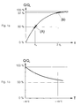
- Figure 1a shows the behavior of the relative resonant circuit quality Q / Q 0 as a function of the distance S (switching distance) of the standard measuring plate of an inductive proximity switch.
- the usable change (Q 0 -Q) in the resonant circuit quality Q caused by the standard measuring plate drops rapidly to a very small value relative to the undamped resonant circuit quality Q 0 .
- the curve in FIG. 1a shows that the influence of the standard measuring plate on the relative resonance circuit quality for a switching distance that is three times as large is approx. 3% reduced (working point B).
- FIG. 1b shows that the ratio Q / Q 0 decreases with increasing temperature.
- FIG. 1a shows that with larger switching distances the temperature influence on Q / Q 0 quickly becomes greater than the change caused by the standard measuring plate. This temperature influence is largely caused by the temperature dependence of the resistance of the voice circuit coil.
- EP-A-0 070 796 describes a method in which the Temperature dependence of the resistance of the Voice coil is used for this, because of this Influence bad temperature behavior of the vibration amplitude of the resonant circuit excited by a generator compensate.
- the generator produces a constant AC of the same frequency as that of the Resonance circuit through the resistance of the voice circuit coil. This method enables the largest at the moment realizable switching distances.
- This known method requires a bifilar coil Achieve the desired compensation of the Temperature influence.
- This type of coil has among other things the disadvantage that one or two additional wires are to be connected. This creates additional costs in the manufacture of both the coil itself and its Connection to the electronic circuit. In addition, the automatic production of both the coil and its Connection very difficult.
- This known oscillator circuit contains resonant circuit quality a feedback of the coil voltage via a Amplifier circuit (D), the size of the gain this amplification circuit (D) by an additional Circuit (E) is set which is a negative Has temperature characteristic, and being a change in Temperature coefficients of the circuit (E) by a change a circuit constant is achieved.
- D Amplifier circuit
- E additional Circuit
- the invention has for its object a Generic oscillator to create, which without the above-mentioned disadvantages an effective compensation of the Effects of the temperature dependence of the resistance of the Voice coil on the vibration behavior of the Vibration circuit ensures that the simple and inexpensive manufacture of inductive proximity switches with large switching distances is possible.
- FIGS Sub-claims emerge.
- FIG. 2 shows the circuit diagram of an oscillator with an LC resonant circuit connected in parallel with a virtual negative resistor.
- the oscillator according to Figure 2 is constructed in a known manner and consists of the resonant circuit formed by the coil L (with inductance L) and the capacitor C (with capacitance C), the copper resistor R CU of the resonant circuit coil L and the amplifier V connected as a negative resistor with the three resistors R 1 , R 2 and R 3 determining the virtual negative resistance R n at point (D).
- the ohmic resistance of the respective resistors R 1 is also referred to as R 1 .
- Resistor R 1 is connected between ground and the inverting (or N-) input of amplifier V.
- the resistor R 2 is connected between the inverting input of the amplifier V and the output of the same.
- the resistor R 3 is connected between the non-inverting (or P-) input of the amplifier V and the output of the same.
- the resonant circuit L, C, R CU is connected between the non-inverting input of the amplifier V and ground.
- the oscillation condition for the oscillator according to FIG. 2 is:
- the resistance R CU of the conductor material of the coil L has a relatively high, positive temperature coefficient which, according to equations (2) and (3), influences the onset and the outset of the oscillation of the resonant circuit.
- the breaking point of the oscillation is determined in a manner known per se as a result of the approach of a standard measuring plate by an evaluation circuit and is used as the switching point for the proximity switch. Any influence of the temperature on this switching point is therefore undesirable.
- the largest temperature influence in known oscillators comes from the resistance R CU of the resonance circuit coil L.
- FIG. 3 shows the circuit diagram of an oscillator according to a first embodiment of the invention.
- the constant current source I 1 which is connected in series with the resonant circuit L, C, R CU between ground and the non-inverting input of the amplifier V, is used to determine the temperature-dependent copper resistance R CU of the resonant circuit coil L.
- a constant voltage source U 0 is connected between the output (F) of the amplifier V 1 and the one input of a multiplier M.
- the voltage source U 0 serves to add a constant voltage of the size k * U 0 to the voltage U V1 at (F). The sum of these voltages is called U e2 .
- the desired voltage can of course also be introduced with an adder.
- the voltage U 0 is the reference voltage of the multiplier M.
- the virtual negative resistance R n is thus controlled inversely proportional to the copper resistance R CU of the oscillating circuit coil L, whereby the temperature dependence of the oscillation behavior of the oscillator according to FIG. 2 caused by R CU is ideally compensated.
- the oscillation condition for the oscillator (see equation (3)) becomes independent of R CU and therefore essentially independent of temperature. This compensates for the influence of the temperature coefficient of the resistance R CU of the resonant circuit coil L on the point of application of the oscillation of the resonant circuit C, L, R CU without the need for a bifilar coil.
- the voice circuit coil L used is a simple coil with one winding and two connections, without any special requirements for the coil.
- the control of the virtual negative resistance R n is inversely proportional to the copper resistance R CU of the oscillating circuit coil L, and thus the temperature compensation of the oscillator, is achieved by multiplying the output voltage U e1 of the amplifier V by a factor that is a linear function of the resistance R CU of the coil L.
- Multiplier M also an execution according to the time division method can be used, or the signal can first digitized and multiplying by one multiplying digital / analog converter can be made.
- the entire control system can also be purely digital, for example with a digital signal processor.
- the current source I 1 is preferably derived from the voltage source U 0 , or vice versa. It is thereby achieved that (according to equation (9): U 0 in the numerator, I 1 in the denominator) the negative resistance R n is not affected by a possible instability of the voltage source U 0 or the current source I 1 . This eliminates the need to stabilize the voltage source U 0 and the current source I 1 .
- the voltage source U 0 can possibly be omitted, with the result that the virtual negative resistance R n is not exactly inversely proportional to the copper resistance R CU of the resonance circuit coil L. The temperature compensation is then a little less good.
- the copper resistance R CU of the oscillating circuit coil L is generally only a few ohms, and the current available in practice for I 1 is of the order of 1 mA.
- the usable voltage U CU is therefore only a few mV. It is difficult to amplify this small voltage with the required accuracy. In particular, the offset voltage of the amplifier V 1 is noticeable. To avoid this problem, the amplifier V 1 can be designed according to the known principle of the chopper amplifier.
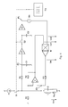
- FIG. 4 shows the circuit diagram of an oscillator according to a further embodiment of the invention.
- the amplifier V 1 instead of designing the amplifier V 1 as a chopper amplifier, a sample-hold circuit is used to amplify the voltage drop U CU .
- the current source I 1 is clocked by means of the clock generator TG and the switch S 1 with the frequency F tg , which is significantly smaller (in the order of magnitude of a few Hz) than F osc .
- the clock ratio of the clock generator TG can be selected to be small in order to reduce the current consumed by the current source I 1 .
- the AC voltage component of the voltage at point (E) is amplified in the non-inverting AC voltage amplifier V 2 .
- the sample voltage circuit consisting of the switch S 2 , the holding capacitor C 2 and the voltage follower V 3 is then restored.
- the offset voltage of the amplifier V 3 is no longer significant compared to the useful voltage U CU already amplified in the amplifier V 2 .
Landscapes
- Inductance-Capacitance Distribution Constants And Capacitance-Resistance Oscillators (AREA)
- Electronic Switches (AREA)
- Stabilization Of Oscillater, Synchronisation, Frequency Synthesizers (AREA)
- Switches That Are Operated By Magnetic Or Electric Fields (AREA)
Applications Claiming Priority (3)
| Application Number | Priority Date | Filing Date | Title |
|---|---|---|---|
| CH1482/96 | 1996-06-13 | ||
| CH01482/96A CH690950A5 (de) | 1996-06-13 | 1996-06-13 | Temperaturstabilisierter Oszillator und Verwendung desselben in einem Näherungsschalter. |
| CH148296 | 1996-06-13 |
Publications (2)
| Publication Number | Publication Date |
|---|---|
| EP0813306A1 EP0813306A1 (de) | 1997-12-17 |
| EP0813306B1 true EP0813306B1 (de) | 2001-10-04 |
Family
ID=4211500
Family Applications (1)
| Application Number | Title | Priority Date | Filing Date |
|---|---|---|---|
| EP97810207A Expired - Lifetime EP0813306B1 (de) | 1996-06-13 | 1997-04-09 | Temperaturstabilisierter Oszillator und Verwendung desselben in einem Näherungsschalter |
Country Status (7)
| Country | Link |
|---|---|
| US (1) | US6031430A (enExample) |
| EP (1) | EP0813306B1 (enExample) |
| JP (2) | JP4620188B2 (enExample) |
| AT (1) | ATE206569T1 (enExample) |
| CA (1) | CA2206025A1 (enExample) |
| CH (1) | CH690950A5 (enExample) |
| DE (1) | DE59704753D1 (enExample) |
Cited By (4)
| Publication number | Priority date | Publication date | Assignee | Title |
|---|---|---|---|---|
| DE102017128472A1 (de) | 2017-11-30 | 2019-06-06 | Pepperl + Fuchs Gmbh | Induktiver Näherungsschalter und Verfahren zum Betreiben eines induktiven Näherungsschalters |
| DE102017128471A1 (de) | 2017-11-30 | 2019-06-06 | Pepperl + Fuchs Gmbh | Induktiver Näherungsschalter und Verfahren zum Betreiben eines induktiven Näherungsschalters |
| EP4030623A1 (de) | 2021-01-15 | 2022-07-20 | Pepperl+Fuchs SE | Induktive sensoreinheit und überwachungsverfahren |
| EP4030135A1 (de) | 2021-01-15 | 2022-07-20 | Pepperl+Fuchs SE | Induktive sensoreinheit |
Families Citing this family (19)
| Publication number | Priority date | Publication date | Assignee | Title |
|---|---|---|---|---|
| GB2365130B (en) * | 2000-07-20 | 2005-01-19 | Honeywell Control Syst | Improved proximity sensor and related methods |
| DE10046147C1 (de) * | 2000-09-15 | 2002-02-21 | Balluff Gmbh | Hochempfindlicher Näherungssensor sowie Verfahren zu seinem Abgleich |
| DE10049758B4 (de) * | 2000-09-29 | 2004-07-22 | Walter Hanke Mechanische Werkstätten GmbH & Co KG | Schaltungsanordnung zur Erzeugung eines Einschaltsignals für batteriebetriebene Münzprüfer |
| US7030626B2 (en) | 2001-06-18 | 2006-04-18 | Yamatake Corporation | High-frequency oscillation type proximity sensor |
| DE10143900A1 (de) * | 2001-09-07 | 2003-03-27 | Sick Ag | Induktiver Näherungssensor |
| US20040238213A1 (en) * | 2003-05-28 | 2004-12-02 | Pitio Walter Michael | Uniform impedance printed circuit board |
| DE602004026260D1 (de) * | 2003-11-06 | 2010-05-12 | Optosys Ag | Kabelpositionssensor |
| DE102005001692B4 (de) * | 2005-01-13 | 2007-04-05 | Pepperl + Fuchs Gmbh | Näherungsschalter und Verfahren zum Betrieb eines Näherungsschalters |
| US7548155B2 (en) * | 2005-02-18 | 2009-06-16 | Saf-Holland, Inc. | Fifth wheel sensor assembly |
| DE502007006613D1 (de) * | 2006-06-27 | 2011-04-14 | Baumer Electric Ag | E sensoren |
| EP2157690B1 (en) * | 2008-08-23 | 2012-01-18 | Si-Ware Systems | Method, system and apparatus for accurate and stable LC-based reference oscillators |
| DE102011115922B4 (de) * | 2011-10-14 | 2019-06-06 | Baumer Electric Ag | Induktiver Sensor |
| DE102013202573B3 (de) * | 2013-02-18 | 2014-04-17 | Ifm Electronic Gmbh | Induktiver Näherungsschalter |
| DE102014202793A1 (de) | 2014-02-17 | 2015-08-20 | Ifm Electronic Gmbh | Induktiver Näherungsschalter |
| US20160268970A1 (en) * | 2015-03-10 | 2016-09-15 | Fred Mirow | Sensitivity variable loop gain oscillator sensor system |
| US9723692B2 (en) | 2015-05-20 | 2017-08-01 | Saf-Holland, Inc | Fifth wheel coupling detection system with inspection and indication lighting arrangement |
| CN108988842B (zh) * | 2018-06-11 | 2022-05-17 | 贵州振华华联电子有限公司 | 一种高可靠小型电感式接近开关 |
| DE102022207939A1 (de) * | 2022-08-01 | 2024-02-01 | MICRO-EPSILON-MESSTECHNIK GmbH & Co. K.G. | Integrierter Schaltkreis für eine Signalverarbeitung eines Sensors und Verfahren zur Steuerung oder Regelung einer Temperatur oder einer Temperaturverteilung in dem Schaltkreis |
| CN116155204B (zh) * | 2023-02-20 | 2025-07-04 | 福州大学 | 一种应用于温度传感器的低功耗rc振荡器 |
Family Cites Families (5)
| Publication number | Priority date | Publication date | Assignee | Title |
|---|---|---|---|---|
| CH655414B (enExample) * | 1981-07-17 | 1986-04-15 | ||
| DE3225193A1 (de) * | 1982-07-06 | 1984-01-12 | Gebhard Balluff Fabrik feinmechanischer Erzeugnisse GmbH & Co, 7303 Neuhausen | Induktiver naeherungsschalter |
| CH675039A5 (enExample) * | 1987-12-01 | 1990-08-15 | Peter Heimlicher | |
| EP0399242B1 (de) * | 1989-05-19 | 1996-03-20 | Festo KG | Temperaturstabiler induktiver Näherungsschalter |
| JPH0563559A (ja) * | 1991-06-26 | 1993-03-12 | Sharp Corp | 発振回路 |
-
1996
- 1996-06-13 CH CH01482/96A patent/CH690950A5/de not_active IP Right Cessation
-
1997
- 1997-04-09 DE DE59704753T patent/DE59704753D1/de not_active Expired - Lifetime
- 1997-04-09 EP EP97810207A patent/EP0813306B1/de not_active Expired - Lifetime
- 1997-04-09 AT AT97810207T patent/ATE206569T1/de not_active IP Right Cessation
- 1997-05-23 CA CA002206025A patent/CA2206025A1/en not_active Abandoned
- 1997-06-12 JP JP15548397A patent/JP4620188B2/ja not_active Expired - Lifetime
- 1997-06-13 US US08/874,251 patent/US6031430A/en not_active Expired - Lifetime
-
2008
- 2008-05-14 JP JP2008127343A patent/JP2008278506A/ja active Pending
Cited By (7)
| Publication number | Priority date | Publication date | Assignee | Title |
|---|---|---|---|---|
| DE102017128472A1 (de) | 2017-11-30 | 2019-06-06 | Pepperl + Fuchs Gmbh | Induktiver Näherungsschalter und Verfahren zum Betreiben eines induktiven Näherungsschalters |
| DE102017128471A1 (de) | 2017-11-30 | 2019-06-06 | Pepperl + Fuchs Gmbh | Induktiver Näherungsschalter und Verfahren zum Betreiben eines induktiven Näherungsschalters |
| EP4030623A1 (de) | 2021-01-15 | 2022-07-20 | Pepperl+Fuchs SE | Induktive sensoreinheit und überwachungsverfahren |
| EP4030135A1 (de) | 2021-01-15 | 2022-07-20 | Pepperl+Fuchs SE | Induktive sensoreinheit |
| DE102021000158A1 (de) | 2021-01-15 | 2022-07-21 | Pepperl+Fuchs Se | Induktive Sensoreinheit |
| DE102021000155A1 (de) | 2021-01-15 | 2022-07-21 | Pepperl+Fuchs Se | Induktive Sensoreinheit und Überwachungsverfahren |
| EP4318949A2 (de) | 2021-01-15 | 2024-02-07 | Pepperl+Fuchs SE | Induktive sensoreinheit und überwachungsverfahren |
Also Published As
| Publication number | Publication date |
|---|---|
| JP2008278506A (ja) | 2008-11-13 |
| CA2206025A1 (en) | 1997-12-13 |
| CH690950A5 (de) | 2001-02-28 |
| EP0813306A1 (de) | 1997-12-17 |
| DE59704753D1 (de) | 2001-11-08 |
| ATE206569T1 (de) | 2001-10-15 |
| JP4620188B2 (ja) | 2011-01-26 |
| US6031430A (en) | 2000-02-29 |
| JPH1075118A (ja) | 1998-03-17 |
Similar Documents
| Publication | Publication Date | Title |
|---|---|---|
| EP0813306B1 (de) | Temperaturstabilisierter Oszillator und Verwendung desselben in einem Näherungsschalter | |
| EP0070796B2 (de) | Verfahren zur Kompensation der Temperaturabhängigkeit der Schwingamplitude eines durch einen Generator angeregten Schwingkreises, nach diesem Verfahren kompensierter Oszillator und Verwendung desselben | |
| DE69400323T2 (de) | Mehrschleifensteuereinrichtung und Verfahren für Leistungsschaltwandler mit Bandpass Stromsteuerung | |
| DE69423488T2 (de) | Spannungsregler | |
| WO2007079955A2 (de) | Auswertungs- und kompensationsschaltung für einen induktiven wegsensor | |
| EP1987592B1 (de) | Induktiver näherungsschalter sowie verfahren zum betreiben eines solchen | |
| DE2232625C3 (de) | Geregelter Gleichspannungswandler | |
| EP0319470B1 (de) | Verfahren und Schaltung zur Reduktion der Temperaturabhängigkeit der Schwingparameter eines Oszillators | |
| DE4018016C2 (de) | Hitzdraht-Luftmengenmesser | |
| DE19611610A1 (de) | Oszillaotr | |
| DE10023306C2 (de) | Verfahren zur Ansteuerung von piezoelektrischen Antrieben in Füllstandmessgeräten | |
| DE3513403A1 (de) | Verfahren zur reduzierung des temperaturverhaltens eines schwingkreises und nach diesem verfahren kompensierter oszillator | |
| EP2033310B1 (de) | Temperaturstabilisierter schwingkreis für induktive sensoren | |
| DE69517882T2 (de) | Schwingungskontrollanlage mit Regelung der Oszillationsfrequenz | |
| EP0358122B1 (de) | Temperatursensor | |
| DE102014004098B4 (de) | Wien-brückenoszillator und schaltungsanordnung zum regulieren einer verstimmung | |
| DE2650777A1 (de) | Breitbandoszillator mit elektrischer frequenzsteuerung | |
| EP0118396B1 (de) | Messverfahren für ein elektrisches Signal, serie-parallel-gegengekoppelter Messkreis sowie Verwendung des Verfahrens oder des Messkreises zur Messung von Spannungsquellen mit höchstohmigen Innenimpedanzen | |
| DE3690374C2 (enExample) | ||
| EP0489259A2 (de) | Kapazitäts-Frequenz-Wandler | |
| EP0403733A1 (de) | Oszillator, insbesondere für einen berührungslos arbeitenden induktiven Näherungssensor oder Näherungsschalter | |
| DE102011075175A1 (de) | Signalübertragungsanordnung mit einem Transformator | |
| EP1388200B1 (de) | Schaltungsanordnung zur spannungsstabilisierung | |
| EP0905883A2 (de) | Temperaturkompensationsschaltung für Feldeffekttransistor-Verstärkerschaltungen | |
| DE3019162C2 (de) | Transistor-Zündschaltung |
Legal Events
| Date | Code | Title | Description |
|---|---|---|---|
| PUAI | Public reference made under article 153(3) epc to a published international application that has entered the european phase |
Free format text: ORIGINAL CODE: 0009012 |
|
| AK | Designated contracting states |
Kind code of ref document: A1 Designated state(s): AT BE DE FR GB IT NL SE |
|
| 17P | Request for examination filed |
Effective date: 19980109 |
|
| 17Q | First examination report despatched |
Effective date: 20000710 |
|
| GRAG | Despatch of communication of intention to grant |
Free format text: ORIGINAL CODE: EPIDOS AGRA |
|
| GRAG | Despatch of communication of intention to grant |
Free format text: ORIGINAL CODE: EPIDOS AGRA |
|
| GRAH | Despatch of communication of intention to grant a patent |
Free format text: ORIGINAL CODE: EPIDOS IGRA |
|
| GRAH | Despatch of communication of intention to grant a patent |
Free format text: ORIGINAL CODE: EPIDOS IGRA |
|
| GRAH | Despatch of communication of intention to grant a patent |
Free format text: ORIGINAL CODE: EPIDOS IGRA |
|
| GRAA | (expected) grant |
Free format text: ORIGINAL CODE: 0009210 |
|
| AK | Designated contracting states |
Kind code of ref document: B1 Designated state(s): AT BE DE FR GB IT NL SE |
|
| PG25 | Lapsed in a contracting state [announced via postgrant information from national office to epo] |
Ref country code: NL Free format text: LAPSE BECAUSE OF FAILURE TO SUBMIT A TRANSLATION OF THE DESCRIPTION OR TO PAY THE FEE WITHIN THE PRESCRIBED TIME-LIMIT Effective date: 20011004 |
|
| REF | Corresponds to: |
Ref document number: 206569 Country of ref document: AT Date of ref document: 20011015 Kind code of ref document: T |
|
| REF | Corresponds to: |
Ref document number: 59704753 Country of ref document: DE Date of ref document: 20011108 |
|
| REG | Reference to a national code |
Ref country code: GB Ref legal event code: IF02 |
|
| PG25 | Lapsed in a contracting state [announced via postgrant information from national office to epo] |
Ref country code: SE Free format text: LAPSE BECAUSE OF FAILURE TO SUBMIT A TRANSLATION OF THE DESCRIPTION OR TO PAY THE FEE WITHIN THE PRESCRIBED TIME-LIMIT Effective date: 20020104 |
|
| RAP2 | Party data changed (patent owner data changed or rights of a patent transferred) |
Owner name: OPTOSYS SA |
|
| GBT | Gb: translation of ep patent filed (gb section 77(6)(a)/1977) |
Effective date: 20011220 |
|
| ET | Fr: translation filed | ||
| NLT2 | Nl: modifications (of names), taken from the european patent patent bulletin |
Owner name: OPTOSYS SA |
|
| NLV1 | Nl: lapsed or annulled due to failure to fulfill the requirements of art. 29p and 29m of the patents act | ||
| PG25 | Lapsed in a contracting state [announced via postgrant information from national office to epo] |
Ref country code: AT Free format text: LAPSE BECAUSE OF NON-PAYMENT OF DUE FEES Effective date: 20020409 |
|
| PG25 | Lapsed in a contracting state [announced via postgrant information from national office to epo] |
Ref country code: BE Free format text: LAPSE BECAUSE OF NON-PAYMENT OF DUE FEES Effective date: 20020430 |
|
| PLBE | No opposition filed within time limit |
Free format text: ORIGINAL CODE: 0009261 |
|
| STAA | Information on the status of an ep patent application or granted ep patent |
Free format text: STATUS: NO OPPOSITION FILED WITHIN TIME LIMIT |
|
| 26N | No opposition filed | ||
| REG | Reference to a national code |
Ref country code: FR Ref legal event code: CA |
|
| REG | Reference to a national code |
Ref country code: FR Ref legal event code: PLFP Year of fee payment: 20 |
|
| PGFP | Annual fee paid to national office [announced via postgrant information from national office to epo] |
Ref country code: DE Payment date: 20160421 Year of fee payment: 20 Ref country code: GB Payment date: 20160421 Year of fee payment: 20 |
|
| PGFP | Annual fee paid to national office [announced via postgrant information from national office to epo] |
Ref country code: IT Payment date: 20160427 Year of fee payment: 20 Ref country code: FR Payment date: 20160421 Year of fee payment: 20 |
|
| REG | Reference to a national code |
Ref country code: DE Ref legal event code: R071 Ref document number: 59704753 Country of ref document: DE |
|
| REG | Reference to a national code |
Ref country code: GB Ref legal event code: PE20 Expiry date: 20170408 |
|
| PG25 | Lapsed in a contracting state [announced via postgrant information from national office to epo] |
Ref country code: GB Free format text: LAPSE BECAUSE OF EXPIRATION OF PROTECTION Effective date: 20170408 |