EP0812990B1 - Pneumatisches Schaltelement - Google Patents
Pneumatisches Schaltelement Download PDFInfo
- Publication number
- EP0812990B1 EP0812990B1 EP96119419A EP96119419A EP0812990B1 EP 0812990 B1 EP0812990 B1 EP 0812990B1 EP 96119419 A EP96119419 A EP 96119419A EP 96119419 A EP96119419 A EP 96119419A EP 0812990 B1 EP0812990 B1 EP 0812990B1
- Authority
- EP
- European Patent Office
- Prior art keywords
- element according
- switching element
- spring
- vacuum
- pneumatic
- Prior art date
- Legal status (The legal status is an assumption and is not a legal conclusion. Google has not performed a legal analysis and makes no representation as to the accuracy of the status listed.)
- Expired - Lifetime
Links
Images

Classifications
-
- F—MECHANICAL ENGINEERING; LIGHTING; HEATING; WEAPONS; BLASTING
- F15—FLUID-PRESSURE ACTUATORS; HYDRAULICS OR PNEUMATICS IN GENERAL
- F15B—SYSTEMS ACTING BY MEANS OF FLUIDS IN GENERAL; FLUID-PRESSURE ACTUATORS, e.g. SERVOMOTORS; DETAILS OF FLUID-PRESSURE SYSTEMS, NOT OTHERWISE PROVIDED FOR
- F15B15/00—Fluid-actuated devices for displacing a member from one position to another; Gearing associated therewith
- F15B15/08—Characterised by the construction of the motor unit
- F15B15/10—Characterised by the construction of the motor unit the motor being of diaphragm type
Definitions
- the invention relates to a pneumatic switching element with those mentioned in the preamble of claim 1 Features.
- Pneumatic designed as a vacuum switch socket Switching elements of the generic type are known. These have one in a pressure chamber Vacuum switch socket mounted by means of a membrane Membrane plate on which when the Pressure chamber with a negative pressure against the force a spring element is displaceable. Through the Displacement of the membrane plate becomes one from the Pressure chamber led out actuated membrane rod, which in turn triggers a switching process. For this can the membrane rod with a rotatably mounted Seesaw connected via a movement of the Membrane rod in a mechanical switching movement is implemented.
- Such vacuum switch boxes are used for example in internal combustion engines, where a switchable suction pipe for the intake air is provided.
- This speed or load-dependent switching of the intake manifold must be in relative short periods of time, for example in the 1/10 second range done effectively.
- the switching process is either by applying vacuum to the vacuum switch socket or by switching off the vacuum and simultaneously Actuation of the diaphragm plate by the spring force of the Spring element causes.
- FR-A-1022093 and DE-A-2830738 show as Vacuum switch trained pneumatic Switching elements with a pressure chamber and with one against the Force of a spring element displaceable actuator.
- claim 1 offers the Advantage that a dead volume of the pneumatic Switching element is minimized.
- the spring element arranged outside the pressure chamber is and attacks the actuator, it is advantageously possible to make the pressure chamber independent from the dimensioning of the spring element the minimum necessary adjustment of the actuator as well as the minimum necessary effective area of the Actuator for applying the required operating force to limit.
- the pressure chamber of the pneumatic Switching element with negative pressure a faster actuation the actuating device, since that to be evacuated Dead volume limited to its minimum is.
- the pneumatic according to the invention switching element a minimization of the dead volume possible.
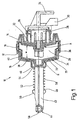
- FIG. 1 is a pneumatic switching means trained vacuum switch 10 in one Sectional view shown.
- the vacuum switch socket 10 has a housing 12 which consists of a first housing part 14 and a second housing part 16 exists.
- the housing parts 14 and 16 are for example rotationally symmetrical and via a locking connection 18 pressure-tight with each other connected.
- Within the housing 12 is by the Housing parts 14 and 16 thus form a pressure chamber 20.
- the housing part 14 has at least a through opening 22 with the pressure chamber 20 connects a terminal 24 which is not with one vacuum source shown is connectable.
- the Housing part 14 forms a receiving area 26, in which a solenoid valve, not shown in detail here 28 is arranged.
- the solenoid valve 28 is between the connection 24 and the pressure chamber 20th switched so that a continuous connection between the vacuum source and the pressure space 20 manufactured or interrupted can.
- the solenoid valve 28 is electrical Connection unit 30 with a not shown Control, for example the electronic control unit connected to a motor vehicle.
- the membrane 34 is on its outer circumference 36 firmly locked to the housing 12, for example clamped between the housing parts 14 and 16.
- the membrane plate 32 is essentially pot-shaped formed, the base plate 38 with the membrane 34 is connected and its coaxial Edge 40 no firm connection with the Has membrane 34.
- the membrane plate 32 is in the FIG. 1 is shown in two positions to be explained, namely in a rest position R and one Working position A.
- the housing part 14 is designed such that the Membrane plate 32 within the housing 12 from the Rest position R in the working position A respectively conversely transferred along a stroke w can be.
- the membrane plate 32 is with a membrane rod 42 firmly connected, the one actuator 44th the vacuum switch socket 10 trains.
- the membrane rod 42 is through a dome 46 of the housing part 16 out.
- the membrane rod 42 has a Bearing 48 trained collar 50 on the one resilient spring element 52 supports one hand.
- the spring element 52 is supported on the Dome 46 of the housing part 16, which thus simultaneously an abutment 54 for the spring element 52 forms.
- the distance between the bearing 48 and the Abutment 54 is chosen so that the spring element 52, which can be, for example, a spiral spring 56 can penetrated by the membrane rod 42 is slightly biased.
- the vacuum switch socket 10 shown in Figure 1 exercises the following function:
- the membrane plate is in the initial state 32 in its rest position R. Will now over the Control unit, not shown, a control command given the solenoid valve 28, this opens and establishes a connection between the vacuum source and the pressure chamber 20 ago. This will Pressure chamber 20 evacuated and then the membrane plate 32 against the force of the spring element 52 from its rest position R to its working position A convicted. Due to the negative pressure exerted an actuating force that is greater than the spring force of the spring element 52 and that of the mechanical device 44 to be applied Force. The membrane plate 32 is along the Stroke w moves, the spring element 52 between the bearing 48 and the abutment 54 compressed, that means being excited.
- the vacuum switch socket shown in Figure 1 10 offers compared to the previously known vacuum switch boxes the advantage that the spring element 52 arranged outside the pressure chamber 20 is. Another advantage is that the Solenoid valve 28 directly in the vacuum path in the immediate Proximity to the pressure chamber 20 is arranged. Through these two measures, the dead volume the vacuum switch socket 10 drastically reduced, so that a transfer of the membrane plate 32 from its Rest position R in its working position A immediately after the solenoid valve 28 responds without great time delay occurs. By dropping out any additional connecting cables of the Solenoid valve on the connection path between the Pressure source and the pressure room will continue Seal risks avoided. It is also advantageous that the membrane plate 32 and thus the membrane 34 in their rest position R is not under a mechanical one Are under tension, since the spring element 52 opposite the known vacuum switch sockets in the rest position R relaxed and in working position A is excited.
- FIGs 2 and 3 is a plan view and a side view of a vacuum switch socket 10 shown according to a further embodiment.
- the same parts as in Figure 1 are given the same reference numerals provided and not explained again.
- FIG directed.
- the spring element 76 is formed as a spiral spiral spring 78, the first End 80 engages in the receptacle 74.
- the second end 82 of the spiral spring 78 engages on the Rocker 60.
- the spiral spring 78 is arranged in such a way that a spring longitudinal axis 84 with the axis of rotation 62 coincides.
- the function of the vacuum switch socket 10 is already using the exemplary embodiment in FIG. 1 explained so that only differences are discussed here shall be.
- the rocker 60 After the pressure chamber 20 over the solenoid valve 28 is connected to the vacuum source the rocker 60 will be from its rest position R into working position A about the axis of rotation 62 pivoted.
- the pin 66 rotated by a corresponding angle, so that a flap attached to the end 68 is one Performs pivoting movement and thereby a switching process, for example switching a pipe length an intake manifold of an internal combustion engine is triggered.
- the spiral spring becomes 78 stretched by the ends projected into a plane 80 and 82 of the spiral spring 78 moved towards each other become.
Landscapes
- Engineering & Computer Science (AREA)
- Physics & Mathematics (AREA)
- Fluid Mechanics (AREA)
- Mechanical Engineering (AREA)
- General Engineering & Computer Science (AREA)
- Actuator (AREA)
- Reciprocating Pumps (AREA)
Description
- Figur 1
- eine Schnittdarstellung durch eine Unterdruckschaltdose,
- Figur 2
- eine Draufsicht auf eine Unterdruckschaltdose nach einem weiteren Ausführungsbeispiel und
- Figur 3
- eine Seitenansicht der Unterdruckschaltdose gemäß Figur 2.
Claims (13)
- Pneumatisches Schaltelement, als Unterdruckschaltdose (10) ausgebildet, mit einem über ein Schaltmittel (28) mit einer Unterdruckquelle verbindbaren Druckraum (20), mit einem den Druckraum (20) umschließenden Gehäuse (12, 14, 16), wobei in dem Druckraum (20) ein gegen die Kraft eines Federelementes (52, 76) durch einen Unterdruck verlagerbares Stellglied (35) angeordnet ist, das Schaltmittel (28) in die Unterdruckschaltdose (10) integriert ist und ein Gehäuseteil (14) des Gehäuses das Schaltmittel (28) mindestens teilweise umschließt.
- Pneumatisches Schaltelement nach Anspruch 1, dadurch gekennzeichnet, dass das Gehäuse (12, 14, 16) einen mit der Unterdruckwelle verbindbaren Anschluss (24) aufweist.
- Pneumatisches Schaltelement nach Anspruch 2, dadurch gekennzeichnet, dass das Schaltmittel (28) direkt in einem Verbindungsweg zwischen dem Anschluss (24) und dem Druckraum (20) der Unterdruckschaltdose (10) angeordnet ist.
- Pneumatisches Schaltelement nach einem der vorhergehenden Ansprüche, dadurch gekennzeichnet, dass das Schaltmittel (28) ein Magnetventil ist.
- Pneumatisches Schaltelement nach einem der vorhergehenden Ansprüche, dadurch gekennzeichnet, dass das Stellglied (35) mit einer aus dem Druckraum (20) herausgeführten Betätigungseinrichtung (44) verbunden ist und das Federelement (52, 76) außerhalb des Druckraums (20) angeordnet ist und an der Betätigungseinrichtung (44) angreift.
- Pneumatisches Schaltelement nach einem der vorhergehenden Ansprüche, dadurch gekennzeichnet, dass das Stellglied (35) ein Membranteller (32) ist.
- Pneumatisches Schaltelement nach Anspruch 5 oder 6, dadurch gekennzeichnet, dass die Betätigungseinrichtung (44) von einer aus der Unterdruckschaltdose (10) herausgeführten Membranstange (42) gebildet wird, die mit dem Federelement (52, 76) zusammenwirkende Mittel aufweist.
- Pneumatisches Schaltelement nach Anspruch 7, dadurch gekennzeichnet, dass die Membranstange (42) ein Lager (48) für das Federelement (52) trägt und das Lager (48) das Federelement (52) bei anliegendem Unterdruck gegen ein Gegenlager (54) spannt.
- Pneumatisches Schaltelement nach Anspruch 8, dadurch gekennzeichnet, dass das Gegenlager (54) von einem Teil (46) des Gehäuses (12) gebildet wird.
- Pneumatisches Schaltelement nach einem der Ansprüche 7 bis 9, dadurch gekennzeichnet, dass das Federelement (52) eine Spiralfeder (56) ist, die von der Membranstange (42) durchgriffen wird.
- Pneumatisches Schaltelement nach Anspruch 5, dadurch gekennzeichnet, dass die Betätigungseinrichtung (44) eine um eine Drehachse (62) verschwenkbare Wippe (60) aufweist, die gleichzeitig ein Lager für das Federelement (76) bildet.
- Pneumatisches Schaltelement nach Anspruch 11, dadurch gekennzeichnet, dass das Federelement (76) eine Biegefeder (78) ist, deren Federachse (84) mit der Drehachse (62) zusammenfällt und die Biegefeder (78) an einem ortsfesten Gegenlager gelagert ist.
- Pneumatisches Schaltelement nach Anspruch 12, dadurch gekennzeichnet, dass das Gegenlager von einem einem Chassis (70) entspringenden Halterarm (72) gebildet wird.
Applications Claiming Priority (2)
| Application Number | Priority Date | Filing Date | Title |
|---|---|---|---|
| DE19623961A DE19623961A1 (de) | 1996-06-15 | 1996-06-15 | Pneumatisches Schaltelement |
| DE19623961 | 1996-06-15 |
Publications (2)
| Publication Number | Publication Date |
|---|---|
| EP0812990A1 EP0812990A1 (de) | 1997-12-17 |
| EP0812990B1 true EP0812990B1 (de) | 2002-07-03 |
Family
ID=7797061
Family Applications (1)
| Application Number | Title | Priority Date | Filing Date |
|---|---|---|---|
| EP96119419A Expired - Lifetime EP0812990B1 (de) | 1996-06-15 | 1996-12-04 | Pneumatisches Schaltelement |
Country Status (2)
| Country | Link |
|---|---|
| EP (1) | EP0812990B1 (de) |
| DE (2) | DE19623961A1 (de) |
Cited By (1)
| Publication number | Priority date | Publication date | Assignee | Title |
|---|---|---|---|---|
| US8567303B2 (en) | 2010-12-07 | 2013-10-29 | General Compression, Inc. | Compressor and/or expander device with rolling piston seal |
Families Citing this family (2)
| Publication number | Priority date | Publication date | Assignee | Title |
|---|---|---|---|---|
| JP4290991B2 (ja) | 2001-03-02 | 2009-07-08 | フイルテルウエルク マン ウント フンメル ゲゼルシヤフト ミツト ベシユレンクテル ハフツング | 負圧作動器 |
| DE102004012130A1 (de) * | 2004-03-12 | 2005-09-29 | Hengst Gmbh & Co.Kg | Pneumatischer Aktor und Verfahren zur Herstellung eines eine Stellmembran und einen Membrantragkörper umfassenden Bauteils für den Aktor |
Family Cites Families (5)
| Publication number | Priority date | Publication date | Assignee | Title |
|---|---|---|---|---|
| FR1022093A (fr) * | 1950-07-17 | 1953-02-27 | Servo-moteur à dépression | |
| DE1301721B (de) * | 1966-12-15 | 1969-08-21 | Honeywell Gmbh | Umkehrbarer Druckmittelantrieb |
| DE2830738C3 (de) * | 1978-07-13 | 1981-10-15 | Pierburg Gmbh & Co Kg, 4040 Neuss | Pneumatisch betätigte Verstellvorrichtung |
| US4391184A (en) * | 1979-10-06 | 1983-07-05 | Ken Yamane | Diaphragm actuator |
| DE3022999C2 (de) * | 1980-06-20 | 1985-03-28 | Pierburg Gmbh & Co Kg, 4040 Neuss | Einrichtung zur betriebsabhängigen Schließbegrenzung einer Vergaser-Hauptdrossel |
-
1996
- 1996-06-15 DE DE19623961A patent/DE19623961A1/de not_active Withdrawn
- 1996-12-04 DE DE59609408T patent/DE59609408D1/de not_active Expired - Lifetime
- 1996-12-04 EP EP96119419A patent/EP0812990B1/de not_active Expired - Lifetime
Cited By (1)
| Publication number | Priority date | Publication date | Assignee | Title |
|---|---|---|---|---|
| US8567303B2 (en) | 2010-12-07 | 2013-10-29 | General Compression, Inc. | Compressor and/or expander device with rolling piston seal |
Also Published As
| Publication number | Publication date |
|---|---|
| EP0812990A1 (de) | 1997-12-17 |
| DE59609408D1 (de) | 2002-08-08 |
| DE19623961A1 (de) | 1997-12-18 |
Similar Documents
| Publication | Publication Date | Title |
|---|---|---|
| DE19924450C1 (de) | Teleskopierbares Staubsauger-Saugrohr | |
| DE69511808T2 (de) | Ventilsteuerungsvorrichtung für mehrzylindrige Brennkraftmaschine | |
| DE19961795C2 (de) | Abgasbremse | |
| DE3302194C2 (de) | ||
| DE102019008860A1 (de) | Ventilbetätigungseinrichtung zum Betätigen wenigstens zweier Gaswechselventile einer Verbrennungskraftmaschine, Verfahren zum Betreiben einer solchen Ventilbetätigungseinrichtung und Verbrennungskraftmaschine | |
| DE3027722A1 (de) | Vakuummotor zum steuern einer vergaserdrosselklappe | |
| EP0418484A1 (de) | Betätigungsvorrichtung für eine in einer Ansaugleitung einer Dieselbrennkraftmaschine angeordneten Drosselklappe | |
| EP0733783B1 (de) | Schwinghebel-Anordnung zur Betätigung eines Hubventils | |
| DE60117737T2 (de) | Lastschalter mit einer mobilen Einheit versehen in einem gasgefüllten Gehäuse | |
| DE102008059207A1 (de) | Nockenfolger zur Betätigung eines Gaswechselventils einer Brennkraftmaschine | |
| DE102009014347A1 (de) | Vergaseranordnung | |
| DE2830738B2 (de) | Pneumatisch betätigte Verstellvorrichtung | |
| EP0812990A1 (de) | Pneumatisches Schaltelement | |
| EP0733790B1 (de) | Verstelleinrichtung | |
| DE102009054687A1 (de) | Viergelenk-Koppelgetriebe sowie Abgasturbolader | |
| DE2120840C2 (de) | Betätigungsvorrichtung für eine Posaune | |
| EP1191170A1 (de) | Schliessvorrichtung für eine Fahrzeugtür | |
| DE19702251C2 (de) | Zentralverriegelungsstellelement für Türen oder Klappen von Kraftfahrzeugen | |
| EP1421263A1 (de) | Lösbare verbindung zum kuppeln eines gaswechselventils einer brennkraftmaschine mit einem aktor | |
| DE3613771C2 (de) | ||
| DE102005062998B4 (de) | Kraftfahrzeugtürverschluss | |
| DE4221647C2 (de) | Vorrichtung zum Abdichten eines Spaltes | |
| DE3116118A1 (de) | Selbsttaetige nachstellvorrichtung fuer eine kupplungsbetaetigung an kraftfahrzeugen | |
| DE19624605C1 (de) | Betätigungsvorrichtung für eine Kupplung | |
| EP0938110A2 (de) | Vorrichtung für das ein- und ausschalten eines Elektromotors, insbesondere eines Elektrowerkzeugs |
Legal Events
| Date | Code | Title | Description |
|---|---|---|---|
| PUAI | Public reference made under article 153(3) epc to a published international application that has entered the european phase |
Free format text: ORIGINAL CODE: 0009012 |
|
| AK | Designated contracting states |
Kind code of ref document: A1 Designated state(s): DE FR GB IT |
|
| 17P | Request for examination filed |
Effective date: 19980617 |
|
| 17Q | First examination report despatched |
Effective date: 20000126 |
|
| GRAG | Despatch of communication of intention to grant |
Free format text: ORIGINAL CODE: EPIDOS AGRA |
|
| GRAG | Despatch of communication of intention to grant |
Free format text: ORIGINAL CODE: EPIDOS AGRA |
|
| GRAH | Despatch of communication of intention to grant a patent |
Free format text: ORIGINAL CODE: EPIDOS IGRA |
|
| GRAH | Despatch of communication of intention to grant a patent |
Free format text: ORIGINAL CODE: EPIDOS IGRA |
|
| GRAA | (expected) grant |
Free format text: ORIGINAL CODE: 0009210 |
|
| AK | Designated contracting states |
Kind code of ref document: B1 Designated state(s): DE FR GB IT |
|
| REF | Corresponds to: |
Ref document number: 59609408 Country of ref document: DE Date of ref document: 20020808 |
|
| GBT | Gb: translation of ep patent filed (gb section 77(6)(a)/1977) |
Effective date: 20020925 |
|
| ET | Fr: translation filed | ||
| PLBE | No opposition filed within time limit |
Free format text: ORIGINAL CODE: 0009261 |
|
| STAA | Information on the status of an ep patent application or granted ep patent |
Free format text: STATUS: NO OPPOSITION FILED WITHIN TIME LIMIT |
|
| 26N | No opposition filed |
Effective date: 20030404 |
|
| PGFP | Annual fee paid to national office [announced via postgrant information from national office to epo] |
Ref country code: GB Payment date: 20041122 Year of fee payment: 9 |
|
| PG25 | Lapsed in a contracting state [announced via postgrant information from national office to epo] |
Ref country code: IT Free format text: LAPSE BECAUSE OF NON-PAYMENT OF DUE FEES;WARNING: LAPSES OF ITALIAN PATENTS WITH EFFECTIVE DATE BEFORE 2007 MAY HAVE OCCURRED AT ANY TIME BEFORE 2007. THE CORRECT EFFECTIVE DATE MAY BE DIFFERENT FROM THE ONE RECORDED. Effective date: 20051204 Ref country code: GB Free format text: LAPSE BECAUSE OF NON-PAYMENT OF DUE FEES Effective date: 20051204 |
|
| GBPC | Gb: european patent ceased through non-payment of renewal fee |
Effective date: 20051204 |
|
| PGFP | Annual fee paid to national office [announced via postgrant information from national office to epo] |
Ref country code: FR Payment date: 20120103 Year of fee payment: 16 |
|
| PGFP | Annual fee paid to national office [announced via postgrant information from national office to epo] |
Ref country code: DE Payment date: 20120221 Year of fee payment: 16 |
|
| REG | Reference to a national code |
Ref country code: FR Ref legal event code: ST Effective date: 20130830 |
|
| REG | Reference to a national code |
Ref country code: DE Ref legal event code: R119 Ref document number: 59609408 Country of ref document: DE Effective date: 20130702 |
|
| PG25 | Lapsed in a contracting state [announced via postgrant information from national office to epo] |
Ref country code: DE Free format text: LAPSE BECAUSE OF NON-PAYMENT OF DUE FEES Effective date: 20130702 |
|
| PG25 | Lapsed in a contracting state [announced via postgrant information from national office to epo] |
Ref country code: FR Free format text: LAPSE BECAUSE OF NON-PAYMENT OF DUE FEES Effective date: 20130102 |