EP0812962B1 - Mehrzweck-Baggerlöffel - Google Patents
Mehrzweck-Baggerlöffel Download PDFInfo
- Publication number
- EP0812962B1 EP0812962B1 EP97115518A EP97115518A EP0812962B1 EP 0812962 B1 EP0812962 B1 EP 0812962B1 EP 97115518 A EP97115518 A EP 97115518A EP 97115518 A EP97115518 A EP 97115518A EP 0812962 B1 EP0812962 B1 EP 0812962B1
- Authority
- EP
- European Patent Office
- Prior art keywords
- bucket
- piston
- lock
- portions
- aforementioned
- Prior art date
- Legal status (The legal status is an assumption and is not a legal conclusion. Google has not performed a legal analysis and makes no representation as to the accuracy of the status listed.)
- Expired - Lifetime
Links
- 230000007246 mechanism Effects 0.000 claims description 13
- 239000003921 oil Substances 0.000 description 32
- 230000033001 locomotion Effects 0.000 description 4
- 230000006837 decompression Effects 0.000 description 3
- 239000012530 fluid Substances 0.000 description 3
- 239000000463 material Substances 0.000 description 3
- 230000009471 action Effects 0.000 description 2
- 238000010276 construction Methods 0.000 description 2
- 230000004048 modification Effects 0.000 description 2
- 238000012986 modification Methods 0.000 description 2
- 230000002093 peripheral effect Effects 0.000 description 2
- 239000000725 suspension Substances 0.000 description 2
- 230000008901 benefit Effects 0.000 description 1
- 239000004568 cement Substances 0.000 description 1
- 239000010727 cylinder oil Substances 0.000 description 1
- 238000007599 discharging Methods 0.000 description 1
- 230000000694 effects Effects 0.000 description 1
- 230000009545 invasion Effects 0.000 description 1
- 239000008267 milk Substances 0.000 description 1
- 210000004080 milk Anatomy 0.000 description 1
- 235000013336 milk Nutrition 0.000 description 1
- 230000007935 neutral effect Effects 0.000 description 1
- 239000004576 sand Substances 0.000 description 1
Images


Classifications
-
- E—FIXED CONSTRUCTIONS
- E02—HYDRAULIC ENGINEERING; FOUNDATIONS; SOIL SHIFTING
- E02F—DREDGING; SOIL-SHIFTING
- E02F3/00—Dredgers; Soil-shifting machines
- E02F3/04—Dredgers; Soil-shifting machines mechanically-driven
- E02F3/28—Dredgers; Soil-shifting machines mechanically-driven with digging tools mounted on a dipper- or bucket-arm, i.e. there is either one arm or a pair of arms, e.g. dippers, buckets
- E02F3/36—Component parts
- E02F3/40—Dippers; Buckets ; Grab devices, e.g. manufacturing processes for buckets, form, geometry or material of buckets
- E02F3/402—Dippers; Buckets ; Grab devices, e.g. manufacturing processes for buckets, form, geometry or material of buckets with means for facilitating the loading thereof, e.g. conveyors
- E02F3/404—Dippers; Buckets ; Grab devices, e.g. manufacturing processes for buckets, form, geometry or material of buckets with means for facilitating the loading thereof, e.g. conveyors comprising two parts movable relative to each other, e.g. for gripping
-
- E—FIXED CONSTRUCTIONS
- E02—HYDRAULIC ENGINEERING; FOUNDATIONS; SOIL SHIFTING
- E02F—DREDGING; SOIL-SHIFTING
- E02F3/00—Dredgers; Soil-shifting machines
- E02F3/04—Dredgers; Soil-shifting machines mechanically-driven
- E02F3/28—Dredgers; Soil-shifting machines mechanically-driven with digging tools mounted on a dipper- or bucket-arm, i.e. there is either one arm or a pair of arms, e.g. dippers, buckets
- E02F3/36—Component parts
- E02F3/3604—Devices to connect tools to arms, booms or the like
- E02F3/3677—Devices to connect tools to arms, booms or the like allowing movement, e.g. rotation or translation, of the tool around or along another axis as the movement implied by the boom or arms, e.g. for tilting buckets
- E02F3/3681—Rotators
-
- Y—GENERAL TAGGING OF NEW TECHNOLOGICAL DEVELOPMENTS; GENERAL TAGGING OF CROSS-SECTIONAL TECHNOLOGIES SPANNING OVER SEVERAL SECTIONS OF THE IPC; TECHNICAL SUBJECTS COVERED BY FORMER USPC CROSS-REFERENCE ART COLLECTIONS [XRACs] AND DIGESTS
- Y10—TECHNICAL SUBJECTS COVERED BY FORMER USPC
- Y10S—TECHNICAL SUBJECTS COVERED BY FORMER USPC CROSS-REFERENCE ART COLLECTIONS [XRACs] AND DIGESTS
- Y10S37/00—Excavating
- Y10S37/903—Scoop or scraper attachments
Definitions
- the present invention relates to a multipurpose bucket structure to be attached to the leading end portion of an arm of a constructing machine such as a power shovel.
- a working machine such as the constructing machine or the power shovel can be used according to its function for constructing works such as a trench digging operation. Because of this simplified function, the machine cannot be sufficiently applied to various constructing works.
- the power shovel of the prior art has a single bucket which is attached to the leading end portion of its arm but which is not equipped with any cover.
- Some power shovel is so modified as to have various attachments. In either case, the functions are so restricted that the working efficiency cannot be enhanced to meet the term of works.
- JP-A-60,175,633 upon which the precharacterising portion of appended claim 1 is based, describes a bucket structure having pivotal bucket parts, the base of one bucket part being attached to a rotary plate allowing the structure to be rotated.
- An object of the present invention is to provide a multipurpose bucket structure for carrying long materials, for pulling down a building into pieces and taking away the pieces, for disassembling an automobile and taking away the parts, for working with a large-sized tool, for digging the ground, for putting the area destroyed by a disaster in order, for carrying ready-mixed concrete and for carrying concrete blocks or secondary products of concrete.
- a multipurpose bucket structure comprising:
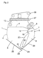
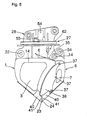
- reference numeral 1 designates a body bucket which is constructed of a back portion 2, righthand and lefthand side portions 3 and a top portion 4.
- the body bucket 1 is opened at 5 at its front portion opposed to the back portion 2.
- numeral 6 designates an openable bucket, which is also constructed of a back portion 7, righthand and lefthand side portions 8 and a top portion 9 and opened at 10 at its front portion.
- These body bucket and openable bucket 1 and 6 are protruded from their respective top portions 4 and 9 to form base portions 12 and 13.
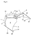
- the body bucket 1 is formed, at the upper end portions of the side portions 3 in the peripheral edges of the opening 5, with a semicircularly recessed back tooth portion 16, which is so faced by a semicircularly recessed back tooth portion 17 formed in the side portions 8 of the openable bucket 6 that the two back tooth portions 16 and 17 can mesh with each other.
- the openable bucket 6 is formed with a higher tooth portion 18 which is farther projected than the back tooth portion 17 to come into the opening 5 inside of the side portions 3 of the body bucket 1.
- the peripheral edges of the opening 5 below the individual back tooth portions 16 and 17 are individually gently recessed to establish a gap 20 between the side portions 3 and 8 of the body bucket 1 and the openable bucket 6.
- the side portions 3 and 8 are formed at their lower end portion below the gap 20 with projecting middle tooth portions 21 and 22, and the back portions 2 and 7 are formed at their leading end portions with front tooth portions 23 and 24 between the side portions 3 and 8.
- the back portions 2 and 7 are inclined below their vertically intermediate portions toward the front tooth portions 23 and 24 to form flat plate portions 25 and 26 so that the two buckets 1 and 6 have the slopes at the lower portions of their back portions.
- the upper base portion 12 of the body bucket 1 is composed of two righthand and lefthand side plates 30, between which is so horizontally arranged a hydraulic cylinder 31 as is directed generally in parallel with the opening/closing directions.
- This hydraulic cylinder 31 has its bottom hinged to the portion just above the back portion 2 of the body bucket 1 at the side opposed to the hinge pin 14 of the openable bucket 6 by means of a hinge pin 32 fitted between the two side plates 30.
- the opposite rod 33 of the hydraulic cylinder 31 has its leading end hinged to the base portion 13 of the openable bucket 6 through a joint pin 34 positioned above the aforementioned pin 14.
- the openable bucket 6 has its leading end turned downward to take a closed position, as shown in Fig. 1, when the hydraulic cylinder 31 has its rod 33 extended, but takes an open position when the rod 33 is contracted.
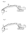
- a mounting base 28 for a working vehicle is attached to the leading end of the arm 29 of the working vehicle, as shown in Fig. 6, so that a bucket structure composed of the body bucket 1 and the openable bucket 6 can be swiveled by 360 degrees with respect to that arm 29.
- Fig. 7 shows the case in which the bucket structure is attached to the arm 29 not through the aforementioned swivel mechanism 27.
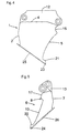
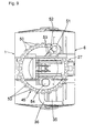
- Figs. 8 to 14 show another embodiment of the present invention.
- the body bucket 1 is formed in the upper face of its top portion 4 with a pouring port 35 for pouring a fluid material for constructions such as cement milk.
- This pouring port 35 is surrounded by a funnel portion 36 which has a sloped upper face.
- the aforementioned gap 20 between the side portions 3 and 8 of the body bucket 1 and the openable bucket 6 is closed by a cover plate 38 which is removably fastened to the side portions 8 in the vicinity of the opening of the openable bucket 6 by means of bolts 37, 37 and 37. While the openable bucket 6 is being closed, the cover plate 38 has its leading end abutting closely against the end portion of the side portions 3 of the body bucket 1. As a result, the fluid material is prevented from overflowing from the gap 20 when it is poured from the aforementioned pouring port 35 or scooped up.
- edge members 40 and 40 for forming the aforementioned front tooth portions 23 and 24 of Fig. 1.
- the edge members 40 and 40 are formed above the front tooth portion 20 with slightly recessed portions 41 and 41.
- the pin 32 supporting the bottom side of the hydraulic cylinder 31 is inserted into a pin bearing hole 44 which is formed in a joint portion 43 integrally formed across the side plates 30 and 30.
- the joint portion 43 is constructed to plug the bottom-side opening of the hydraulic cylinder 31 to prevent invasion of sand as much as possible.
- the side plates 30 and 30, the joint portion 43 and the mounting plate 45 constitute altogether a box for protecting the hydraulic cylinder 31.
- a lock valve 46 which is equipped with a decompression mechanism for holding the hydraulic cylinder 31 at a predetermined extension.
- Numeral 48 designates an oil pressure piping to the hydraulic cylinder 31.
- This hydraulic cylinder 31 can be used for various works by replacing the openable bucket by another attachment.
- the aforementioned mounting plate 45 has a round shape, as seen from a top plan view of Fig. 9, and is formed along its outer circumference with a number lock holes 50.
- a lock cylinder 51 which can have its rod inserted into one of the lock holes 50 to lock the aforementioned bucket structure in a horizontally swiveled arbitrary position.
- Numeral 52 designates a relief valve which is disposed midway of an oil pressure piping 53 to that lock cylinder 51.
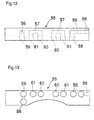
- numeral 55 designates a piping case disposed in one portion of the aforementioned mounting base 28.
- This piping case 55 is equipped with oil passages 56 for a swiveling hydraulic motor and oil passages 57 for a hydraulic cylinder, as shown in Figs. 12 and 13.
- the oil passages 56 have their one port 58 connected with the piping of the lock cylinder 51 and their other port 59 connected with the piping of the hydraulic motor.
- This swiveling hydraulic motor 54 is mounted on the swivel mechanism 27, as shown in Fig. 8, to drive the same for the swiveling motions.
- the cylinder oil passage 57 has its one port 60 connected with one chamber of the hydraulic cylinder 31 through a not-shown rotary joint and its other port 61 connected with the not-shown piping of the hydraulic pump.
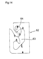
- Fig. 14 shows a side of a retaining portion for a suspension hook, which is attached to the outer face of one base portion 12 above the body bucket 1.
- This suspension hook retaining portion 62 is composed of a groove 63 for inserting a hook and a lock lever 64 made turnable to close one portion of the groove 63.
- the retaining portion 62 thus composed has its lock lever 64 turned outward and prevented from coming out when the hook or the like is fitted in the groove 63.
- Figs. 15 and 16 show a bucket structure according to another embodiment.
- the respective side portions of the body bucket 1 and the openable bucket 6 are formed with the middle tooth portions 21 and 22, one of which is recessed whereas the other of which is projected.
- the edge members 40 and 40 are attached for forming those middle tooth portions 21 and 22.
- the body bucket 1 and the openable bucket 6 of Fig. 16 are not formed with the sloped side portions but have their back portions bulging outward.
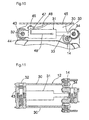
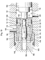
- Fig. 17 shows the aforementioned swivel locking mechanism in detail.
- a cylindrical lock pin guide 70 into which is vertically movably inserted a lock pin 71.
- This lock pin 71 has its lower end inserted into one of the lock holes 50 of the aforementioned mounting plate 45, to lock the swiveling motion of the mounting plate 45.
- the lock pin guide 71 has its internal diameter enlarged at its upper end. Into this enlarged portion, there is inserted the lower end of the aforementioned lock cylinder 51.
- This lock cylinder 51 has its internal diameter gradually reduced at an upward first step portion 72 and an upward second step portion 73 positioned below the former.
- first piston 74 which is formed on its outer circumference with such downward step portions 85 and 92 for abutting against the aforementioned step portions 72 and 73.
- the first piston 74 has a cylindrical shape having a bottom portion 75 at its lower end.
- pin-push pin 76 Diametrically through the first piston 74, there is so inserted a pin-push pin 76 as to abut against the inner face of the bottom portion 75.
- This pin-push pin 76 has its two ends extending through a vertically long bore 90, which is formed in the circumferential wall of the first piston 74, and fixed by the aforementioned lock pin 71.
- a rod-shaped second piston 77 as to have its lower end abutting against the aforementioned pin-push pin 76.
- a flange 78 formed on the outer circumference of the cylinder 51 is fixed on the aforementioned mounting base 28 by means of bolts 79 inserted downward. These bolts 79 have their leading ends driven into a support member 80 positioned below the mounting base 28.
- the lock cylinder 51 has its upper end opening closed by a spring seat 49.
- first spring 86 is mounted between the back of the spring seat 49 and an inward step portion 87 of the aforementioned first piston 74
- second spring 89 is mounted between the back of the spring seat 49 and a spring receiving step portion on the outer circumference of the second piston 77.
- the lock cylinder 51 is formed in its outer circumference with inlet ports 81 and 82 for feeding working oil to the upper portions of the aforementioned first and second step portions 72 and 73, and outlet ports 83 and 84 above and for those inlet ports 81 and 82.
- the working fluid is fed from the inlet ports 81 and 82, its pressure acts upon the individual step portions 85 and 86 of the first piston 74 to lift the first piston 74 against the force of the first spring 86.
- the lock pin 71 is pulled upward through the pin-push pin 76 to release the locked state.
- the second piston 77 is also lifted against the force of the second spring 89.
- the inlet ports 81 and 82 acquire communication with the outlet ports 83 and 84, respectively, so that the working oil is fed from the outlet ports 83 and 84 to the aforementioned swivel cylinder.
- the swiveling motion is also interrupted so that the first piston 74 is pushed back by the individual forces of the springs 86 and 89 to bring the lock pin 71 into one of the lock holes 50 to effect the swivel lock.
- the first piston 74 can move downward ahead of the second piston 77 within a range of the long bore 90 so that a quick locking action can be achieved.
- the swivel mechanism is automatically locked and unlocked in accordance with the feed and interruption of the working oil to the swivel motor.
- numeral 91 designates a bearing for guiding the turning motion of the mounting plate 45.
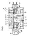
- Figs. 18 and 19 show a structure of the lock valve 46 with a decompression mechanism for locking the aforementioned hydraulic cylinder 31.
- valve fitting bore 101 extending through a valve cylinder 100 to the right and left of Figs. 18 and 19, there is slidably fitted a main piston 103 which is formed with projections at its two ends.
- the valve fitting bore 101 has its two end openings closed with bolts 105 fastened therein.
- a threaded hole 106 at the leading end of each mounting bolt 105, there is driven one end of a cylindrical casing 107 so that the main piston 103 is fitted in the aforementioned bore 101.
- the casing 107 is radially reduced at the end opposed to the bolt 105.
- a valve body 109 which has its outer circumference tapered at its intermediate portion.
- the casing 107 is formed in a position corresponding to the outer circumference of the valve body 109 with a communication hole 110 for providing communication between the inside and outside of the casing 107.
- the taper portion has its outer circumference 111 abutting against a valve seat 112 at the inner end of the reduced portion 108 of the casing 107 to break the communication between the aforementioned communication hole 110 and oil pressure chambers 113 and 114 at the two sides of the main piston 103.
- a smaller piston 115 which has its outer circumference formed into two larger and smaller portions across a longitudinally taper portion 120.
- the smaller piston 115 has its smaller portion 121 protruded from the leading end of the valve body 109.
- the valve body 109 has its through hole 116 formed into two larger and smaller portions corresponding to the external diameters of the smaller piston 115, to leave small clearances 118 and 119 between itself and the smaller piston 115.
- the aforementioned taper portion 120 is held in abutment against a valve seat 123 at the inner end of the smaller portion.
- the valve body 109 is formed with a communication hole 124 for providing communication between the aforementioned communication hole 110 and the clearance 118 around the outer circumference of the larger portion of the smaller piston 115.
- a spring fitting hole 125 formed in the bottom of the threaded hole 106 of the mounting bolt 105 and the inner end of the smaller piston 115 there is mounted a spring 126 for pushing the taper portion 120 of the smaller piston 115 to the aforementioned valve seat 123.
- the valve cylinder 100 is formed with two inlet passages 128 and 129 which are connected to the aforementioned oil pressure chambers 113 and 114, respectively, for introducing the working oil from the working oil pump into the oil pressure chambers 113 and 114.
- the valve cylinder 100 is further formed with a pair of outlet passages 130 and 131 which are connected with the communication hole 110 of the aforementioned casing 107 for introducing the working oil from the communication hole 110 to the bottom and rod of the aforementioned hydraulic cylinder 31.
- one outlet passage 130 communicating with the lefthand oil pressure chamber 114 is bypassed in a hook shape to communicate with the outside through an outlet port 132 which is formed in the back at the center of the main piston 103.
- one inlet passage 129 is used for feeding the working oil to the bottom side of the hydraulic cylinder 31, whereas the other inlet passage 128 is used for feeding the working oil to the rod side of the same.
- the working oil enters, when fed from its pump to the inlet passage 129 at the bottom side, to the corresponding oil pressure chamber 114.
- the pressure of the working oil thus fed to the oil pressure chamber 114 slides the main piston 103 to the left of the drawings so that the projection 102 at the leading end of the main piston 103 pushes and moves the smaller piston 103, as shown in Fig. 19, to the left of the drawings.
- the taper portion 120 leaves the valve seat 123 of the valve body 109 so that the outlet passage 130 comes into communication with the oil pressure chamber 113 through the clearances 118 and 119 around the outer circumference of the smaller piston 115 and through the communication holes 124 and 110.
- the working oil at the rod side is relieved to the drain side to release the pressure of the rod side chamber gradually.
- valve body 109 is pushed and moved in the same direction by the main piston 103 so that it leaves the valve seat 123 of the casing 107 to drain out the working oil of the rod side chamber substantially.
- the substantial release of the working oil is not carried out before the working oil in the bottom side chamber or the rod side chamber is slightly returned to the drain side.
- the openable bucket does not start its opening/closing action abruptly but has its operation simplified.
- the working oil having entered the oil pressure chamber 114 at the bottom side slides the valve body 109 at the bottom side to the right of the drawings so that the communication between the inlet passage 129 and the outlet passage 131 is established through the communication hole 110 to feed the working oil to the bottom side of the hydraulic cylinder 31.
- the hydraulic cylinder 31 is extended while discharging the working oil of the rod side by the pressure at the bottom side thereby to open the aforementioned openable bucket 6.
- the valve body 109 is held in the original position by the force of the spring 126 so that any passage is shut out to lock the openable bucket 6 in its open state.
Claims (3)
- Mehrzweck-Baggerlöffel mit einem eine obere Backe bildenden Hauptlöffel (1) sowie einem eine untere Backe bildenden Löffel (6), der sich öffnen lässt, dadurch gekennzeichnet, dass die Löffel so mit einander gelenkig verbunden sind, dass ihre vorderen Endteile (23, 34) geöffnet und geschlossen werden können, dass der Hauptlöffel (1) so angeordnet ist, dass er an einer Baumaschine mit einem Montierteil (27) solcherart befestigt ist, dass er in einer Ebene senkrecht zu einer Ebene, in welcher der sich öffnen lassende Löffel (6) geöffnet und geschlossen wird, schwenken kann, und dadurch gekennzeichnet, dass der Hauptlöffel (1) so angeordnet ist, dass er durch einen Arretierstift (1), welcher durch eine Schwenkarretierung bewegt wird, in einer vorbestimmten Schwenkstellung arretiert wird.
- Mehrzweck-Baggerlöffel nach Anspruch 1, dadurch gekennzeichnet, dass der Schwenkarretiermechanismus (51) einen Kolben (51) umfasst, dass der Kolben (51) durch Öldruck des Öldruckkreislaufs (53) bewegbar ist und dass der Arretierstift (71) an dem Kolben (51) befestigt ist.
- Mehrzweck-Baggerlöffel nach Anspruch 1, dadurch gekennzeichnet, dass der Arretierstift (71) einen Endteil aufweist, welcher in eine der Arretieröffnungen (50) einer Montierplatte (45) eingesetzt ist, an welcher der Hauptlöffel (1) so angebracht ist, dass das Schwenken des Hauptlöffels (1) arretiert wird.
Applications Claiming Priority (4)
| Application Number | Priority Date | Filing Date | Title |
|---|---|---|---|
| JP5139784A JPH06316947A (ja) | 1993-05-05 | 1993-05-05 | 多目的作業可能なバケット構造装置 |
| JP13978493 | 1993-05-05 | ||
| JP139784/93 | 1993-05-05 | ||
| EP94303213A EP0623709A3 (de) | 1993-05-05 | 1994-05-04 | Mehrzweckbaggerlöffel. |
Related Parent Applications (2)
| Application Number | Title | Priority Date | Filing Date |
|---|---|---|---|
| EP94303213.6 Division | 1994-05-04 | ||
| EP94303213A Division EP0623709A3 (de) | 1993-05-05 | 1994-05-04 | Mehrzweckbaggerlöffel. |
Publications (3)
| Publication Number | Publication Date |
|---|---|
| EP0812962A2 EP0812962A2 (de) | 1997-12-17 |
| EP0812962A3 EP0812962A3 (de) | 1999-12-01 |
| EP0812962B1 true EP0812962B1 (de) | 2002-11-06 |
Family
ID=15253350
Family Applications (3)
| Application Number | Title | Priority Date | Filing Date |
|---|---|---|---|
| EP97115519A Withdrawn EP0812963A3 (de) | 1993-05-05 | 1994-05-04 | Mehrzweck-Baggerlöffel |
| EP94303213A Withdrawn EP0623709A3 (de) | 1993-05-05 | 1994-05-04 | Mehrzweckbaggerlöffel. |
| EP97115518A Expired - Lifetime EP0812962B1 (de) | 1993-05-05 | 1994-05-04 | Mehrzweck-Baggerlöffel |
Family Applications Before (2)
| Application Number | Title | Priority Date | Filing Date |
|---|---|---|---|
| EP97115519A Withdrawn EP0812963A3 (de) | 1993-05-05 | 1994-05-04 | Mehrzweck-Baggerlöffel |
| EP94303213A Withdrawn EP0623709A3 (de) | 1993-05-05 | 1994-05-04 | Mehrzweckbaggerlöffel. |
Country Status (8)
| Country | Link |
|---|---|
| US (1) | US5649377A (de) |
| EP (3) | EP0812963A3 (de) |
| JP (1) | JPH06316947A (de) |
| CN (1) | CN1051132C (de) |
| AU (1) | AU6188994A (de) |
| CA (1) | CA2122890C (de) |
| DE (1) | DE69431676D1 (de) |
| TW (1) | TW274571B (de) |
Families Citing this family (42)
| Publication number | Priority date | Publication date | Assignee | Title |
|---|---|---|---|---|
| AU685692B2 (en) * | 1994-12-23 | 1998-01-22 | Atlas Heavy Engineering Pty Ltd | Excavator bucket |
| DE19531338A1 (de) * | 1995-08-25 | 1996-09-12 | Alexander Schneider | Baggerausstattung |
| CH693222A5 (de) * | 1997-07-15 | 2003-04-30 | Robert Schnyder | Greifer für einen Bagger, Baggersowie Verwendungen derselben insbesondere imForstbereich. |
| AU708473B2 (en) * | 1997-09-19 | 1999-08-05 | Warrick Stanley Pitcher and Wendy Pitcher as Trustees of the Pitcher Holding Trust | Grab attachment for backhoe or excavator buckets |
| US6139212A (en) * | 1998-02-11 | 2000-10-31 | Rockland Manufacturing Co. | Coupler for excavating machines and the like having fixed and moveable jaws |
| EP0939169A1 (de) * | 1998-02-27 | 1999-09-01 | MaK System Gesellschaft mbH | Baggerlöffel mit Greifer |
| US7000339B1 (en) | 1999-08-31 | 2006-02-21 | Ramun John R | Demolition equipment having universal tines and a method for designing a universal tine |
| US6370801B1 (en) * | 1999-11-23 | 2002-04-16 | 1994 Weyer Family Limited Partnership | Hydraulic collection tool |
| US6523284B1 (en) | 2000-02-14 | 2003-02-25 | Scot J. Clugston | Multi-purpose material handling apparatus |
| US6357993B1 (en) * | 2000-02-17 | 2002-03-19 | Farmers' Factory Company | Construction equipment implement and method |
| CA2400917A1 (en) * | 2000-07-31 | 2002-02-07 | Rockland, Inc. | Thumb for a backhoe |
| US7111419B1 (en) | 2000-07-31 | 2006-09-26 | Rockland, Inc. | Thumb for a backhoe |
| US6435581B1 (en) | 2001-02-13 | 2002-08-20 | James L. House | Three-yard concrete bucket with integral ladder |
| ITGE20030015A1 (it) * | 2003-02-25 | 2004-08-26 | Gianluca Malacrino | Benna o pala a capacita' regolabile |
| DE102004015414A1 (de) * | 2004-03-26 | 2005-10-13 | Holp Gmbh | Arbeitswerkzeug für eine Erdbaumaschine |
| KR100609494B1 (ko) * | 2005-05-24 | 2006-08-08 | 임영주 | 집게를 구비한 굴삭기용 버킷 어셈블리 |
| US7631404B2 (en) * | 2005-09-08 | 2009-12-15 | Donald Scruggs | Easy inter burial container |
| GB2436853B (en) * | 2006-04-06 | 2010-12-22 | Bartholomew Prendergast | A coupling |
| US20090282710A1 (en) * | 2007-08-08 | 2009-11-19 | Johnson Rick D | Multi-Function Material Moving Assembly and Method |
| US7617619B2 (en) * | 2007-10-31 | 2009-11-17 | Entek Manufacturing, Inc. | Prehensile bucket attachment |
| DE202008012488U1 (de) * | 2008-09-19 | 2010-02-11 | Kinshofer Gmbh | Zweischalengreifer |
| CN101649627B (zh) * | 2009-09-29 | 2011-08-31 | 黄银飞 | 一种多功能翻斗式液压挖掘机挖斗 |
| US8225537B2 (en) * | 2009-09-30 | 2012-07-24 | Scruggs Donald E | Positioning and rotating apparatus for interring screw-in and self digging burial containers |
| US8112913B2 (en) * | 2009-10-30 | 2012-02-14 | Chester Lea Sirr | Multi-purpose bucket |
| US20120152629A1 (en) * | 2010-12-15 | 2012-06-21 | Mather Daniel T | Hydraulic system having load lock valve |
| CN104285013A (zh) * | 2012-03-01 | 2015-01-14 | 哈尼施费格尔技术公司 | 用于动力铲车铲斗门的闩锁系统 |
| JP5117628B1 (ja) * | 2012-06-27 | 2013-01-16 | Jhl株式会社 | 把持装置及び建設機械 |
| CN102995692A (zh) * | 2012-09-11 | 2013-03-27 | 广西参皇养殖集团有限公司 | 一种新颖料斗 |
| CN103255795A (zh) * | 2013-04-09 | 2013-08-21 | 常熟建工建设集团有限公司苏州分公司 | 一种带有防护翼结构的挖掘机铲斗 |
| CN105887951A (zh) * | 2014-11-13 | 2016-08-24 | 杨双来 | 一种挖掘机抓举机构及控制方法 |
| CN104372820A (zh) * | 2014-12-08 | 2015-02-25 | 常州市家虹包装有限公司 | 防漏式挖掘机铲斗 |
| CN104535350A (zh) * | 2014-12-30 | 2015-04-22 | 贵州詹阳动力重工有限公司 | 一种液压挖掘机通用型实验铲斗 |
| WO2017161458A1 (en) * | 2016-03-23 | 2017-09-28 | Ami Attachments Inc. | Robust multi-tool assembly for hydraulic excavators |
| US10774501B2 (en) * | 2016-03-23 | 2020-09-15 | Ami Attachments Inc. | Robust multi-tool assembly for hydraulic excavators |
| US10631373B2 (en) | 2016-05-12 | 2020-04-21 | Ford Global Technologies, Llc | Heated windshield indicator |
| CN106402062B (zh) * | 2016-12-05 | 2019-01-08 | 河海大学常州校区 | 一种双铲斗挖掘机液压系统 |
| WO2019076425A1 (en) * | 2017-10-16 | 2019-04-25 | Volvo Construction Equipment Ab | CLOSABLE BUCKET ASSEMBLY FOR A WORKING MACHINE |
| WO2019183447A1 (en) | 2018-03-23 | 2019-09-26 | Cashman Dredging And Marine Contracting Co., Llc | Slope-level-cut bucket |
| CN109469135A (zh) * | 2018-11-07 | 2019-03-15 | 马鞍山沐及信息科技有限公司 | 一种挖掘机用铲斗 |
| US11781283B2 (en) * | 2019-05-20 | 2023-10-10 | B-Lair Research And Development Llc | Grappling apparatus and methods of making and using same |
| IT201900012456A1 (it) * | 2019-07-22 | 2021-01-22 | Dai Pra S R L | Benna pinzante per macchina escavatrice |
| CN111021680B (zh) * | 2019-12-25 | 2021-11-19 | 山东大学 | 一种铲灰浆抹墙机及使用方法 |
Family Cites Families (29)
| Publication number | Priority date | Publication date | Assignee | Title |
|---|---|---|---|---|
| US827635A (en) * | 1905-03-13 | 1906-07-31 | Thames Ironworks Shipbuilding & Engineering Company Ltd | Grab. |
| US2328715A (en) * | 1941-09-24 | 1943-09-07 | Hi Way Service Corp | Excavator |
| US3344540A (en) * | 1963-12-19 | 1967-10-03 | Ulrich Mfg Co | Universal load handling apparatus |
| US3252606A (en) * | 1964-03-23 | 1966-05-24 | Claude E Pryor | Front end loader |
| GB1145736A (en) * | 1965-08-24 | 1969-03-19 | Coustol Holdings Ltd | Improvements in or relating to material moving apparatus |
| US3461968A (en) * | 1966-04-28 | 1969-08-19 | Rca Corp | Screening loader |
| US3413029A (en) * | 1966-08-01 | 1968-11-26 | Esco Corp | Material handling apparatus |
| GB1249330A (en) * | 1967-10-26 | 1971-10-13 | Orenstein & Koppel Ag | Bucket for a hydraulic excavator |
| US3737059A (en) * | 1971-02-22 | 1973-06-05 | Caterpillar Tractor Co | Bucket arrangement |
| US3767070A (en) * | 1971-04-13 | 1973-10-23 | Wain Roy | Lifting and excavating apparatus |
| US3814269A (en) * | 1972-05-30 | 1974-06-04 | Caterpillar Tractor Co | Hook for excavator buckets |
| FR2226353B1 (de) * | 1973-04-18 | 1977-02-04 | Poclain Sa | |
| US3941262A (en) * | 1974-02-01 | 1976-03-02 | Caterpillar Tractor Co. | Pivotally disposable bucket |
| DE2838346C2 (de) * | 1978-09-02 | 1985-02-14 | Fa. Heinz Thumm, 7012 Fellbach | Drehvorrichtung für einen Baggergreifer o.dgl. |
| JPS5838049Y2 (ja) * | 1979-02-17 | 1983-08-27 | 淳次 小川 | 両掴みバケット |
| US4375345A (en) * | 1981-07-23 | 1983-03-01 | J. I. Case Company | Clamping arm assembly for a backhoe |
| US4561199A (en) * | 1982-12-30 | 1985-12-31 | Lockwood Michael W | Combination spacer and lifting device for machinery incorporating a bucket |
| US4542929A (en) * | 1983-09-01 | 1985-09-24 | Possinger Warren K | Articulating clam type grapple for a backhoe |
| JPS60175633A (ja) * | 1984-02-23 | 1985-09-09 | Katsunori Tanada | 回転式長尺物把持用掘削バケツト装置 |
| JPS61130528A (ja) * | 1984-11-26 | 1986-06-18 | Katsunori Tanada | 土砂すくい取り用バケット装置兼生コン運搬用バケット装置 |
| IN172013B (de) * | 1985-11-04 | 1993-03-13 | Holmdahl Ulf Goeran | |
| US4669494A (en) * | 1986-08-13 | 1987-06-02 | Teleflex Incorporated | Hydraulic lock valve with partial return to tank for marine steering |
| SE464643B (sv) * | 1988-09-16 | 1991-05-27 | Rolf Mannbro | Anordning vid rotoraggregat |
| EP0363899A1 (de) * | 1988-10-11 | 1990-04-18 | Hitachi Construction Machinery Co., Ltd. | Schwenkbare Schaufelanordnung |
| US5398430A (en) * | 1991-05-20 | 1995-03-21 | Scott; Thomas M. | Earth moving and compacting rig |
| US5311684A (en) * | 1990-05-04 | 1994-05-17 | Rudolf Van Dalfsen | Scooping apparatus, vehicle and coupling plate therefore |
| JPH0424584U (de) * | 1990-06-25 | 1992-02-27 | ||
| JPH0471801U (de) * | 1990-10-26 | 1992-06-25 | ||
| JP2964000B2 (ja) * | 1991-05-22 | 1999-10-18 | 克紀 棚田 | バケット装置の目くら板自動閉鎖装置 |
-
1993
- 1993-05-05 JP JP5139784A patent/JPH06316947A/ja active Pending
-
1994
- 1994-05-04 CN CN94105595A patent/CN1051132C/zh not_active Expired - Fee Related
- 1994-05-04 EP EP97115519A patent/EP0812963A3/de not_active Withdrawn
- 1994-05-04 AU AU61889/94A patent/AU6188994A/en not_active Abandoned
- 1994-05-04 CA CA002122890A patent/CA2122890C/en not_active Expired - Fee Related
- 1994-05-04 EP EP94303213A patent/EP0623709A3/de not_active Withdrawn
- 1994-05-04 EP EP97115518A patent/EP0812962B1/de not_active Expired - Lifetime
- 1994-05-04 DE DE69431676T patent/DE69431676D1/de not_active Expired - Lifetime
- 1994-05-04 US US08/237,874 patent/US5649377A/en not_active Expired - Fee Related
- 1994-06-01 TW TW083105004A patent/TW274571B/zh active
Also Published As
| Publication number | Publication date |
|---|---|
| CA2122890C (en) | 2000-08-08 |
| CA2122890A1 (en) | 1994-11-06 |
| EP0812962A3 (de) | 1999-12-01 |
| EP0812962A2 (de) | 1997-12-17 |
| JPH06316947A (ja) | 1994-11-15 |
| EP0623709A3 (de) | 1995-06-28 |
| CN1051132C (zh) | 2000-04-05 |
| EP0812963A2 (de) | 1997-12-17 |
| EP0623709A2 (de) | 1994-11-09 |
| AU6188994A (en) | 1994-11-10 |
| DE69431676D1 (de) | 2002-12-12 |
| US5649377A (en) | 1997-07-22 |
| CN1099085A (zh) | 1995-02-22 |
| TW274571B (de) | 1996-04-21 |
| EP0812963A3 (de) | 1999-12-01 |
Similar Documents
| Publication | Publication Date | Title |
|---|---|---|
| EP0812962B1 (de) | Mehrzweck-Baggerlöffel | |
| KR101928795B1 (ko) | 굴삭기용 회전링크 | |
| EP2167738B1 (de) | Schnellkopplungsanordnung zur verbindung eines gerätes mit einem maschinenarm | |
| US6902346B2 (en) | Hydraulic coupler | |
| AU773725B2 (en) | Connection apparatus | |
| DE60126081T2 (de) | Hybridmaschine mit hydraulischem antrieb | |
| US20100189535A1 (en) | Coupler device to connect bucket or tool to boom arm | |
| JPH11315551A (ja) | 建設機械における迅速接続装置 | |
| US6874338B1 (en) | Hydraulic piston locking device | |
| AU704767B2 (en) | Multipurpose bucket structure | |
| KR101739779B1 (ko) | 굴삭기의 스마트 집게용 처짐방지장치 | |
| US5433522A (en) | Hydraulic control device for closed type kneader | |
| EP3725953B1 (de) | Schnellkopplerverbindungssystem für baumaschine | |
| KR19980044674A (ko) | 굴착기용 버켓 | |
| EP2662500B1 (de) | Verriegelbare Verlängerung für Arbeitswerkzeug | |
| KR200427300Y1 (ko) | 작업장치의 어태치먼트 연결장치 | |
| US20130259623A1 (en) | Construction machine | |
| KR102642834B1 (ko) | 중장비용 어태치먼트 커플러의 마운트 | |
| KR102430342B1 (ko) | 중장비용 커플러 | |
| JP7059856B2 (ja) | 作業機械用ロック機構、及び、作業機械 | |
| KR102616192B1 (ko) | 다중 안전장치가 구비된 굴삭기용 퀵커플러 | |
| KR100490592B1 (ko) | 유압 브레이커의 안전밸브 | |
| KR102105629B1 (ko) | 퀵 커플러 | |
| KR100402328B1 (ko) | 스키드 스티어로더의 주행시 페달조작 방지장치 | |
| JP2005307560A (ja) | 旋回作業機のウエイト |
Legal Events
| Date | Code | Title | Description |
|---|---|---|---|
| PUAI | Public reference made under article 153(3) epc to a published international application that has entered the european phase |
Free format text: ORIGINAL CODE: 0009012 |
|
| 17P | Request for examination filed |
Effective date: 19970908 |
|
| AC | Divisional application: reference to earlier application |
Ref document number: 623709 Country of ref document: EP |
|
| AK | Designated contracting states |
Kind code of ref document: A2 Designated state(s): BE DE FR GB IT SE |
|
| PUAL | Search report despatched |
Free format text: ORIGINAL CODE: 0009013 |
|
| AK | Designated contracting states |
Kind code of ref document: A3 Designated state(s): BE DE FR GB IT SE |
|
| 17Q | First examination report despatched |
Effective date: 20010607 |
|
| GRAG | Despatch of communication of intention to grant |
Free format text: ORIGINAL CODE: EPIDOS AGRA |
|
| GRAG | Despatch of communication of intention to grant |
Free format text: ORIGINAL CODE: EPIDOS AGRA |
|
| GRAH | Despatch of communication of intention to grant a patent |
Free format text: ORIGINAL CODE: EPIDOS IGRA |
|
| RAP1 | Party data changed (applicant data changed or rights of an application transferred) |
Owner name: TANADA, KATSUNORI |
|
| RIN1 | Information on inventor provided before grant (corrected) |
Inventor name: TANADA, KATSUNORI |
|
| GRAH | Despatch of communication of intention to grant a patent |
Free format text: ORIGINAL CODE: EPIDOS IGRA |
|
| GRAA | (expected) grant |
Free format text: ORIGINAL CODE: 0009210 |
|
| AC | Divisional application: reference to earlier application |
Ref document number: 623709 Country of ref document: EP |
|
| AK | Designated contracting states |
Kind code of ref document: B1 Designated state(s): BE DE FR GB IT SE |
|
| PG25 | Lapsed in a contracting state [announced via postgrant information from national office to epo] |
Ref country code: IT Free format text: LAPSE BECAUSE OF FAILURE TO SUBMIT A TRANSLATION OF THE DESCRIPTION OR TO PAY THE FEE WITHIN THE PRESCRIBED TIME-LIMIT;WARNING: LAPSES OF ITALIAN PATENTS WITH EFFECTIVE DATE BEFORE 2007 MAY HAVE OCCURRED AT ANY TIME BEFORE 2007. THE CORRECT EFFECTIVE DATE MAY BE DIFFERENT FROM THE ONE RECORDED. Effective date: 20021106 Ref country code: FR Free format text: LAPSE BECAUSE OF FAILURE TO SUBMIT A TRANSLATION OF THE DESCRIPTION OR TO PAY THE FEE WITHIN THE PRESCRIBED TIME-LIMIT Effective date: 20021106 Ref country code: BE Free format text: LAPSE BECAUSE OF FAILURE TO SUBMIT A TRANSLATION OF THE DESCRIPTION OR TO PAY THE FEE WITHIN THE PRESCRIBED TIME-LIMIT Effective date: 20021106 |
|
| REG | Reference to a national code |
Ref country code: GB Ref legal event code: FG4D |
|
| REF | Corresponds to: |
Ref document number: 69431676 Country of ref document: DE Date of ref document: 20021212 |
|
| PG25 | Lapsed in a contracting state [announced via postgrant information from national office to epo] |
Ref country code: SE Free format text: LAPSE BECAUSE OF FAILURE TO SUBMIT A TRANSLATION OF THE DESCRIPTION OR TO PAY THE FEE WITHIN THE PRESCRIBED TIME-LIMIT Effective date: 20030206 |
|
| PG25 | Lapsed in a contracting state [announced via postgrant information from national office to epo] |
Ref country code: DE Free format text: LAPSE BECAUSE OF FAILURE TO SUBMIT A TRANSLATION OF THE DESCRIPTION OR TO PAY THE FEE WITHIN THE PRESCRIBED TIME-LIMIT Effective date: 20030207 |
|
| EN | Fr: translation not filed | ||
| PLBE | No opposition filed within time limit |
Free format text: ORIGINAL CODE: 0009261 |
|
| STAA | Information on the status of an ep patent application or granted ep patent |
Free format text: STATUS: NO OPPOSITION FILED WITHIN TIME LIMIT |
|
| 26N | No opposition filed |
Effective date: 20030807 |
|
| PGFP | Annual fee paid to national office [announced via postgrant information from national office to epo] |
Ref country code: GB Payment date: 20040505 Year of fee payment: 11 |
|
| PG25 | Lapsed in a contracting state [announced via postgrant information from national office to epo] |
Ref country code: GB Free format text: LAPSE BECAUSE OF NON-PAYMENT OF DUE FEES Effective date: 20050504 |
|
| GBPC | Gb: european patent ceased through non-payment of renewal fee |
Effective date: 20050504 |