EP0812959B1 - Verbindung zwischen Schwellenabschnitten - Google Patents
Verbindung zwischen Schwellenabschnitten Download PDFInfo
- Publication number
- EP0812959B1 EP0812959B1 EP97109464A EP97109464A EP0812959B1 EP 0812959 B1 EP0812959 B1 EP 0812959B1 EP 97109464 A EP97109464 A EP 97109464A EP 97109464 A EP97109464 A EP 97109464A EP 0812959 B1 EP0812959 B1 EP 0812959B1
- Authority
- EP
- European Patent Office
- Prior art keywords
- plate
- insert
- sleeper
- sections
- resiliently supported
- Prior art date
- Legal status (The legal status is an assumption and is not a legal conclusion. Google has not performed a legal analysis and makes no representation as to the accuracy of the status listed.)
- Expired - Lifetime
Links
- 241001669679 Eleotris Species 0.000 title claims abstract description 32
- 229920001971 elastomer Polymers 0.000 claims description 4
- 239000000806 elastomer Substances 0.000 claims description 4
- 230000002093 peripheral effect Effects 0.000 claims 2
- 238000013016 damping Methods 0.000 description 3
- 230000000149 penetrating effect Effects 0.000 description 2
- 239000002023 wood Substances 0.000 description 2
- 230000015572 biosynthetic process Effects 0.000 description 1
- 230000015556 catabolic process Effects 0.000 description 1
- 230000005284 excitation Effects 0.000 description 1
- 230000003068 static effect Effects 0.000 description 1
Images

Classifications
-
- E—FIXED CONSTRUCTIONS
- E01—CONSTRUCTION OF ROADS, RAILWAYS, OR BRIDGES
- E01B—PERMANENT WAY; PERMANENT-WAY TOOLS; MACHINES FOR MAKING RAILWAYS OF ALL KINDS
- E01B3/00—Transverse or longitudinal sleepers; Other means resting directly on the ballastway for supporting rails
- E01B3/48—Distance keepers or tie-rods for sleepers
-
- E—FIXED CONSTRUCTIONS
- E01—CONSTRUCTION OF ROADS, RAILWAYS, OR BRIDGES
- E01B—PERMANENT WAY; PERMANENT-WAY TOOLS; MACHINES FOR MAKING RAILWAYS OF ALL KINDS
- E01B3/00—Transverse or longitudinal sleepers; Other means resting directly on the ballastway for supporting rails
- E01B3/28—Transverse or longitudinal sleepers; Other means resting directly on the ballastway for supporting rails made from concrete or from natural or artificial stone
- E01B3/38—Longitudinal sleepers; Longitudinal sleepers integral or combined with tie-rods; Combined longitudinal and transverse sleepers; Layers of concrete supporting both rails
Definitions
- the invention relates to a connection between threshold sections, in particular Sections of a long sleeper, while maintaining or substantially while maintaining the distance between the threshold sections that are relative and at least vertical to each other are movable.
- the Plate element is provided with connecting elements which are elastically supported with respect to this connected to a base plate, which in turn each has a screw element with the sleeper section is connected, which in turn passes through the plate element at a distance and is supported against this via an elastic ring.
- the intermediate plate is over elastic connecting elements connected to each threshold section. Besides, it is required for the function that the base plate with the screw element with the respective Threshold section is connected, the screw elements themselves over the elastic Rings are supported on the plate element.
- the variety of elastic required Elements must be of high quality, so that in the on the threshold sections arranged rails always regardless of the static and dynamic loads track-like conditions prevail.
- the present invention is based on the problem of connecting the input further described type in such a way that with structurally simple measures a Connection between the threshold sections is possible, in particular sections of Wooden sleepers, whereby vibrations generated in the sleeper sections are eradicated, to rule out any influence on the substructure.
- the problem is solved according to the invention essentially by that of claim 1 Measures resolved, d. H. through a connection between threshold sections, in particular sections of a long sleeper, while maintaining or essentially below Maintaining the distance between the threshold sections that are relative and at least can be moved vertically to one another, the connection being between the threshold sections extending and connectable to them via a connecting element such as a screw Includes plate element that with one of the threshold sections over a single elastically supported with respect to the plate element and by the connecting element enforced use is connected, which in turn is form-fitting indirectly or directly is connected to the threshold section.
- a connecting element such as a screw
- a section of an intermediate plate in the form of a ribbed plate extends over which the positive connection between the elastically supported insert can be achieved by projections on the underside like pens from the elastically supported insert in corresponding receptacles like Engage the holes in the ribbed plate.
- the connection between the threshold sections ensuring plate element, which is a vertical Allows movement between the threshold sections, but in a horizontal direction Extensive spacing protection is granted via an elastically supported insert takes place, the elastically supportable insert essentially stationary on the associated Threshold section by means of the screw penetrating the insert or another equivalent element is secured.
- non-displaceable elastically supported insert can then in the plate element move the desired extent, especially in the vertical direction, so that a constant Countersink for each of the rails arranged on a sleeper section is possible, at the same time the required vibration damping with vibration excitation from at least one of the threshold sections.
- the plate element itself can be connected to the other (second) threshold section Connection element are connected, which is a breakdown of the plate element enforced, which in turn is surrounded by a circumferential projecting edge, or one second insert, which protrudes on the bottom side above the plate element, so that Plate element is free on the underside.
- the second insert itself is not specifically elastic the intermediate plate supported. Rather, it is a z. B. by pressing inserted insert, which excludes a relative movement to the intermediate plate or at least largely excludes.
- the second insert has a circumferential collar that in a spaced and preferably parallel to the underside of the plate element Level lies in which the elastically supported insert with its lower edge runs.
- the plate element itself preferably has an oval shape with it in a plan view End tapering area, with a longitudinal rib and an oval on the top Area stiffening occurs. This stiffening area extends perpendicular to Longitudinal direction of the plate element, at the same time as a receptacle for the elastically supported Use to be trained.
- the insert can be supported against the plate element by an elastomer that both on the insert and on the intermediate plate, namely on its circumferential Edge of a recess present in the plate element and receiving the insert is vulcanized.
- the elastically supported insert preferably two protrusions like pins, which in corresponding receptacles in the Threshold section or an intermediate plate arranged on this, such as a rib plate intervene so that the elastically supported insert is secured against rotation is.
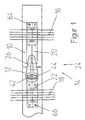
- 1 and 2 sections 10, 12 z. B. a wooden threshold shown to each other are spaced apart, but are connected to one another via a connection 14, that a relative movement in the vertical direction, i.e. perpendicular to the plane of the drawing, however not in the horizontal direction, i.e. in the drawing plane. It is therefore said to be in a soft connection in the vertical direction and essentially a connection in the horizontal direction rigid connection. Vibration damping is also intended by means of the connection 14 in that one of the threshold sections is excited when vibrating 10, 12 a transfer to the other threshold section 12, 10 at an immediate Damping leads, so that changes in the track bed are largely excluded.
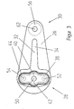
- the plate member 26 which is an oval shape in plan view with a wider first end portion 28 and a narrower second end region 30 can be a forged part, in which a stiffening area 32 is worked out, which consists of a longitudinal rib 34 and a oval survey 36, which is perpendicular to the longitudinal axis of the plate member 26 in the wider end region 28 runs.
- the stiffening area 36 there is an elliptical, continuous recess 38 with a expanded central area 40 in which an insert 42 is elastic over preferably an elastomer 44 is supported.
- the elastomer 44 which runs around the insert 42 surrounds both on the insert 42 and on the circumferential edge of the recess 38 be vulcanized.
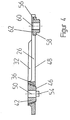
- the elastic support of the insert 42 in the recess 38 allows a relative movement occur between the insert 42 and the plate member 26, the rigidity and formation of the elastic layer 44 is selected such that in the vertical direction, 3 a softer connection perpendicular to the plane of the drawing than in a horizontal one Direction, i.e. in the direction of the drawing plane.
- the insert 42 projects beyond its lower one Edge 46 of the plate element 26 on the underside, the edge 46 preferably in a to Underside 48 of the plate element 26 lies in a parallel plane.
- the insert 46 is penetrated by a central bore 50, through which the insert 42 also the ribbed plate 22 and thus the threshold section 12 is connected as is screwed.
- pins 42, 54 start from the insert, which in corresponding recesses of the Rip plate 22 engage to achieve a desired positive connection.
- the insert 26 tapers to Bottom, that is to the underside 48 of the plate element 26.
- the cross section is corresponding the recess or opening 38 in the bottom area of the plate element 26 is smaller than on the top side.
- the cross section of the insert 42 is on its upper surface larger than the cross section of the recess 38 in the bottom area.
- the insert 42 it is not absolutely necessary for the insert 42 to have a cross section Has trapezoidal shape. Rather, it can also have a rectangular shape.
- the plate element 26 is with the other threshold section 10 via the ribbed plate 20 connected, but no elastically supported insert is required. Rather can an approximately rigid connection can be selected, but in addition to a non-positive connection Connection with the rib plate 20 additionally a positive connection with this should be done.
- an insert 56 with a circumferential collar 58 is in the plate element 26 introduced, which can be inserted into a corresponding receptacle of the rib plate 20 and on this rests with its collar 58.
- the insert 56 is penetrated by a bore 60 which in a going from the top of the plate member 62 hole that leads to Connecting the plate element 26 to the ribbed plate 20 and the threshold section 10 is penetrated by a connecting element, not shown, such as a wood screw.
- the insert 56 can be designed eccentrically with respect to the bore 62 or as a polygon to change the distance to the sleeper portion by rotating the insert 12. to achieve. Furthermore, the insert 56 can also be used to prevent rotation relative to the Rib plate 20 or another intermediate plate or the threshold section 10 be trained.
- the second insert 56 can also be made in one piece with the plate element 26 trained, i.e. forged as a whole.
- both the elastically supported insert 42 with the rib plate 22 and the plate element 26 can be connected to the ribbed plate 20 both non-positively and positively there is the advantage that the horizontal forces which are exerted on the connection 14 transferred from the threshold section 10 to the threshold section 12 and vice versa can be largely from the otherwise the rib plates 20, 22 on the sleeper sections 10, 12 securing screws 64, 66 are included, an advantage that is is particularly noticeable with wooden sleepers.
Landscapes
- Engineering & Computer Science (AREA)
- Architecture (AREA)
- Civil Engineering (AREA)
- Structural Engineering (AREA)
- Connection Of Plates (AREA)
- Railway Tracks (AREA)
- Combinations Of Printed Boards (AREA)
- Adhesive Tapes (AREA)
- Mutual Connection Of Rods And Tubes (AREA)
- Road Paving Structures (AREA)
Description
- Fig. 1
- eine Draufsicht auf über ein Plattenelement verbindbare Schwellenabschnitte,
- Fig. 2
- einen Längsschnitt durch die Verbindung nach Fig. 1,
- Fig. 3
- in Draufsicht und in vergrößerter Darstellung das den Fig. 1 und 2 zu entnehmende Plattenelement und
- Fig. 4
- einen Längsschnitt durch das Plattenelement nach Fig. 3.
Claims (11)
- Verbindung (14) zwischen Schwellenabschnitten (10, 12), insbesondere Abschnitten einer Langschwelle, unter Beibehaltung oder im wesentlichen unter Beibehaltung des Abstandes zwischen den Schwellenabschnitten, die relativ und zumindest vertikal zueinander bewegbar sind, wobei die Verbindung ein zwischen den Schwellenabschnitten verlaufendes und mit diesen über ein Verbindungselement wie Schraube verbindbares Plattenelement (26) umfasst, das mit einem der Schwellenabschnitte (12) über einen einzigen gegenüber dem Plattenelement elastisch abgestützten und von dem Verbindungselement durchsetzten Einsatz (42) verbunden ist, der seinerseits formschlüssig mittelbar oder unmittelbar mit dem Schwellenabschnitt verbunden ist.
- Verbindung nach Anspruch 1,
dadurch gekennzeichnet, dass der elastisch abgestützte (erste) Einsatz (42) über zumindest einen Vorsprung wie Stift (52, 54) unmittelbar oder mittelbar über eine Zwischenplatte wie insbesondere Rippenplatte (22) mit dem ersten Schwellenabschnitt (12) formschlüssig verbunden ist, wobei der Einsatz insbesondere verdrehsicher mit dem ersten Schwellenabschnitt (12) oder einer auf diesem angeordneten Zwischenplatte wie insbesondere verlängerten Rippenplatte (20) verbunden ist. - Verbindung nach Anspruch 1 oder 2,
dadurch gekennzeichnet, dass das Plattenelement (26) einen einzigen und dem einen (ersten) Schwellenabschnitt (12) zugeordneten elastisch abgestützten (ersten) Einsatz (42) aufweist und dass das Plattenelement mit dem anderen (zweiten) Schwellenabschnitt (10) gegebenenfalls über eine Zwischenplatte wie Rippenplatte (20) unmittelbar verbunden ist. - Verbindung nach zumindest einem der vorhergehenden Ansprüche,
dadurch gekennzeichnet, dass das Plattenelement (26) mit dem anderen (zweiten) Schwellenabschnitt (10) über ein zweites Verbindungselement wie Schraube verbunden ist, das eine Durchbrechung (62) des Plattenelementes durchsetzt, die von einem auf der Zwischenplatte (20) bzw. dem zweiten Schwellenabschnitt sich abstützenden Rand umgeben ist, oder einen in das Plattenelement einbringbaren (zweiten) Einsatz (56) durchsetzt, der seinerseits unterseitig über dem Plattenelement vorsteht. - Verbindung nach zumindest einem der vorhergehenden Ansprüche,
dadurch gekennzeichnet, dass der zweite, starr oder im wesentlichen starr mit dem Plattenelement (26) verbundene Einsatz (56) einen umlaufenden Bund (58) aufweist, der in einer beabstandeten und vorzugsweise parallel zur Unterseite (48) des Plattenelements (26) verlaufenden Ebene liegt, in der der elastisch abgestützte (erste) Einsatz (42) mit seinem unteren Rand (46) verläuft, und dass vorzugsweise der elastisch abgestützte Einsatz (42) schwellenseitig über dem Plattenelement (26) derart vorsteht, dass das Plattenelement unterseitig frei ist. - Verbindung nach zumindest einem der vorhergehenden Ansprüche,
dadurch gekennzeichnet, dass das Plattenelement (26) in Draufsicht eine ovale Form mit sich zu einem Ende (30) hin verjüngenden Bereich aufweist, wobei der elastisch abgestützte (erste) Einsatz (42) im Endbereich (28) breiterer Erstreckung verläuft, und dass vorzugsweise der den elastisch abgestützten insbesondere in Draufsicht eine ovale Form aufweisende, mit seiner Längsachse senkrecht zu der des Plattenelementes (26) verlaufende Einsatz (42) aufnehmende Bereich (28) des Plattenelements (26) als Erhebung ausgebildet ist, die in eine in Längsrichtung des Plattenelementes verlaufende Versteifungsrippe (34) übergeht. - Verbindung nach zumindest einem der vorhergehenden Ansprüche,
dadurch gekennzeichnet, dass der elastisch abgestützte (erste) Einsatz (42) vorzugsweise über zwei Vorsprünge wie Stifte (52, 54) formschlüssig mit der Zwischenplatte (22) vorzugsweise in Form einer Rippenplatte verbunden ist und über eine diese und den elastisch abgestützten Einsatz kraftschlüssig verbindende Schraube mit dem Schwellenabschnitt (12) verbunden ist. - Verbindung nach zumindest einem der vorhergehenden Ansprüche,
dadurch gekennzeichnet, dass der elastisch abgestützte Einsatz (42) in einer dessen Außengeometrie angepaßten Aussparung (38) des Plattenelementes (26) eingesetzt und gegenüber diesem über eine elastische Zwischenlage wie Elastomer (44) abgestützt ist, wobei insbesondere die elastische Zwischenlage an dem Einsatz (42) und an diesen umgebendem umlaufenden Rand der Aussparung (38) anvulkanisiert ist. - Verbindung nach zumindest einem der vorhergehenden Ansprüche,
dadurch gekennzeichnet, dass sich der elastisch abgestützte Einsatz (42) zur Unterseite (48) des Plattenelements (26) hin verjüngt und dass die den Einsatz aufnehmende Aussparung (38) einen derart angepaßten Geometrieverlauf aufweist, dass das Plattenelement bei gesichertem Einsatz unverlierbar von diesem gehalten ist. - Verbindung (14) zwischen Schwellenabschnitten (10, 12), insbesondere Abschnitten einer Langschwelle, unter Beibehaltung oder im wesentlichen unter Beibehaltung des Abstandes zwischen den Schwellenabschnitten, die sowohl vertikal als auch horizontal zueinander bewegbar sind, wobei die Verbindung ein zwischen den Schwellenabschnitten verlaufendes und mit diesen über ein Verbindungselement wie Schraube verbindbares Plattenelement (26) mit zumindest einem gegenüber diesem elastisch abgestützten Einsatz (42) umfasst und wobei zwischen dem Plattenelement und dem jeweiligen Schwellenabschnitt gegebenenfalls jeweils eine Zwischenplatte (20, 22) angeordnet ist,
dadurch gekennzeichnet, dass das Plattenelement (26) mit dem einen (ersten) der Schwellenabschnitte (12) über den von dem Verbindungselement durchsetzten elastisch abgestützten (ersten) Einsatz (42) verbunden ist, der seinerseits verdrehgesichert mittelbar oder unmittelbar mit dem ersten Schwellenabschnitt verbunden ist. - Verbindung nach zumindest einem der vorhergehenden Ansprüche,
dadurch gekennzeichnet, dass zwischen dem Plattenelement (26) und dem jeweiligen Schwellenabschnitt (10, 12) jeweils eine Zwischenplatte (20, 22) angeordnet ist.
Applications Claiming Priority (2)
| Application Number | Priority Date | Filing Date | Title |
|---|---|---|---|
| DE19623189 | 1996-06-11 | ||
| DE19623189A DE19623189A1 (de) | 1996-06-11 | 1996-06-11 | Verbindung zwischen Schwellenabschnitten |
Publications (3)
| Publication Number | Publication Date |
|---|---|
| EP0812959A2 EP0812959A2 (de) | 1997-12-17 |
| EP0812959A3 EP0812959A3 (de) | 1998-05-20 |
| EP0812959B1 true EP0812959B1 (de) | 2001-10-04 |
Family
ID=7796580
Family Applications (1)
| Application Number | Title | Priority Date | Filing Date |
|---|---|---|---|
| EP97109464A Expired - Lifetime EP0812959B1 (de) | 1996-06-11 | 1997-06-11 | Verbindung zwischen Schwellenabschnitten |
Country Status (4)
| Country | Link |
|---|---|
| EP (1) | EP0812959B1 (de) |
| AT (1) | ATE206495T1 (de) |
| DE (2) | DE19623189A1 (de) |
| ES (1) | ES2165544T3 (de) |
Families Citing this family (6)
| Publication number | Priority date | Publication date | Assignee | Title |
|---|---|---|---|---|
| DE10030998A1 (de) * | 2000-06-30 | 2002-01-10 | Schenck Process Gmbh | Schwelle zur Auflage von Eisenbahnschienen |
| GB2421264A (en) * | 2004-12-14 | 2006-06-21 | Balfour Beatty Plc | Rail bearer joint |
| GB2431956A (en) * | 2005-11-02 | 2007-05-09 | Balfour Beatty Plc | Rail bearer joint and rail baseplate for use in the joint |
| DE102010035675A1 (de) * | 2010-08-27 | 2012-03-01 | Db Netz Ag | Klappbare Weiche |
| ES2401011B1 (es) * | 2011-09-27 | 2014-04-25 | Jez Sistemas Ferroviarios, S.L. | Elemento de unión de traviesas de aparatos de vía |
| AT521152B1 (de) * | 2018-08-08 | 2019-11-15 | Kirchdorfer Fertigteilholding Gmbh | Eisenbahnschwelle |
Family Cites Families (2)
| Publication number | Priority date | Publication date | Assignee | Title |
|---|---|---|---|---|
| DE4201631A1 (de) * | 1992-01-22 | 1993-07-29 | Butzbacher Weichenbau Gmbh | Schwelle fuer schienen eines oberbaus fuer schienenfahrzeuge |
| DE4313822A1 (de) * | 1993-04-28 | 1994-11-03 | Butzbacher Weichenbau Gmbh | Schwelle für Schienen eines Oberbaus für Schienenfahrzeuge |
-
1996
- 1996-06-11 DE DE19623189A patent/DE19623189A1/de not_active Withdrawn
-
1997
- 1997-06-11 ES ES97109464T patent/ES2165544T3/es not_active Expired - Lifetime
- 1997-06-11 AT AT97109464T patent/ATE206495T1/de not_active IP Right Cessation
- 1997-06-11 EP EP97109464A patent/EP0812959B1/de not_active Expired - Lifetime
- 1997-06-11 DE DE59704752T patent/DE59704752D1/de not_active Expired - Fee Related
Also Published As
| Publication number | Publication date |
|---|---|
| EP0812959A2 (de) | 1997-12-17 |
| ATE206495T1 (de) | 2001-10-15 |
| EP0812959A3 (de) | 1998-05-20 |
| ES2165544T3 (es) | 2002-03-16 |
| DE19623189A1 (de) | 1997-12-18 |
| DE59704752D1 (de) | 2001-11-08 |
Similar Documents
| Publication | Publication Date | Title |
|---|---|---|
| DE102007045466B3 (de) | System zum Befestigen einer Schiene | |
| DE202006020567U1 (de) | System zur Befestigung einer Schiene | |
| EP0641409B1 (de) | Dehnungsstoss für ein gleisteil | |
| EP3215676B1 (de) | Schienenbefestigungspunkt und unterlegplatte | |
| EP0812959B1 (de) | Verbindung zwischen Schwellenabschnitten | |
| DE60019286T2 (de) | Verstellbare eisenbahnschienenbefestigung und verfahren zu deren verwendung | |
| WO2005017258A1 (de) | Anordnung zum umstellen einer zungenschiene zu einer backenschiene | |
| DE4406105A1 (de) | Befestigungsanordnung für eine Schiene | |
| DE2314144A1 (de) | Gleisschwelle und gleisbefestigungsanordnung unter verwendung dieser gleisschwelle | |
| EP0546363A1 (de) | Zwischenlage zwischen einer Unterlageplatte und einer Unterlage eines Oberbaus | |
| EP0698145B1 (de) | Schwelle für schienen eines oberbaus für schienenfahrzeuge | |
| EP0275604B1 (de) | Unterlagsplatte für die Befestigung der Schienen von Eisenbahngleisen und -weichen auf Holzschwellen | |
| DE4212786C2 (de) | Schienenanordnung | |
| EP0778372B1 (de) | Gleitstuhl | |
| EP0455236B1 (de) | Schienenbefestigungsmittel | |
| DE10128844B4 (de) | Vorrichtung zum Befestigen von Schienen auf einem festen Untergrund | |
| DE102004060419B3 (de) | Herzstück für Weichen | |
| EP1221505B1 (de) | Schiene und Vorrichtung zum Befestigen von Schienen | |
| EP1221506B1 (de) | Stützpunkt für eine Schiene | |
| EP3870756B1 (de) | Abstützung für eine schiene | |
| DE4212679A1 (de) | Anordnung einer Schiene | |
| DE4214756A1 (de) | Dehnungsstoß für ein Gleisteil | |
| DE800757C (de) | Schienenbefestigung | |
| DE1534073C3 (de) | Vorrichtung zum Abstützen einer Schiene | |
| DE19607588A1 (de) | Anordnung zum Niederhalten einer Herzstückspitze |
Legal Events
| Date | Code | Title | Description |
|---|---|---|---|
| PUAI | Public reference made under article 153(3) epc to a published international application that has entered the european phase |
Free format text: ORIGINAL CODE: 0009012 |
|
| AK | Designated contracting states |
Kind code of ref document: A2 Designated state(s): AT BE CH DE GB ES FI FR GB GR IE IT LI LU MC NL PT SE |
|
| AX | Request for extension of the european patent |
Free format text: AL;LT;LV;RO;SI |
|
| RIN1 | Information on inventor provided before grant (corrected) |
Inventor name: KUNITZ, WALTER DR. Inventor name: NUDING, ERICH Inventor name: KAIS, ALFRED Inventor name: BENENOWSKI, SEBASTIAN Inventor name: DEMMIG, ALBRECHT Inventor name: DIETZE, HANS-ULRICH |
|
| PUAL | Search report despatched |
Free format text: ORIGINAL CODE: 0009013 |
|
| AK | Designated contracting states |
Kind code of ref document: A3 Designated state(s): AT BE CH DE DK ES FI FR GB GR IE IT LI LU MC NL PT SE |
|
| AX | Request for extension of the european patent |
Free format text: AL;LT;LV;RO;SI |
|
| 17P | Request for examination filed |
Effective date: 19980602 |
|
| AKX | Designation fees paid |
Free format text: AT BE CH DE DK ES FI FR GB GR IE IT LI LU MC NL PT SE |
|
| AXX | Extension fees paid |
Free format text: AL;LT;LV;RO;SI |
|
| RAP1 | Party data changed (applicant data changed or rights of an application transferred) |
Owner name: BWG BUTZBACHER WEICHENBAU GESELLSCHAFT MBH & CO. K |
|
| RBV | Designated contracting states (corrected) |
Designated state(s): AT DE ES FR GB |
|
| 17Q | First examination report despatched |
Effective date: 19991220 |
|
| GRAG | Despatch of communication of intention to grant |
Free format text: ORIGINAL CODE: EPIDOS AGRA |
|
| GRAG | Despatch of communication of intention to grant |
Free format text: ORIGINAL CODE: EPIDOS AGRA |
|
| GRAG | Despatch of communication of intention to grant |
Free format text: ORIGINAL CODE: EPIDOS AGRA |
|
| GRAH | Despatch of communication of intention to grant a patent |
Free format text: ORIGINAL CODE: EPIDOS IGRA |
|
| GRAH | Despatch of communication of intention to grant a patent |
Free format text: ORIGINAL CODE: EPIDOS IGRA |
|
| GRAA | (expected) grant |
Free format text: ORIGINAL CODE: 0009210 |
|
| AK | Designated contracting states |
Kind code of ref document: B1 Designated state(s): AT DE ES FR GB |
|
| REF | Corresponds to: |
Ref document number: 206495 Country of ref document: AT Date of ref document: 20011015 Kind code of ref document: T |
|
| REF | Corresponds to: |
Ref document number: 59704752 Country of ref document: DE Date of ref document: 20011108 |
|
| RAP2 | Party data changed (patent owner data changed or rights of a patent transferred) |
Owner name: BWG GMBH & CO. KG |
|
| REG | Reference to a national code |
Ref country code: GB Ref legal event code: IF02 |
|
| GBT | Gb: translation of ep patent filed (gb section 77(6)(a)/1977) |
Effective date: 20020124 |
|
| ET | Fr: translation filed | ||
| REG | Reference to a national code |
Ref country code: ES Ref legal event code: FG2A Ref document number: 2165544 Country of ref document: ES Kind code of ref document: T3 |
|
| PLBE | No opposition filed within time limit |
Free format text: ORIGINAL CODE: 0009261 |
|
| STAA | Information on the status of an ep patent application or granted ep patent |
Free format text: STATUS: NO OPPOSITION FILED WITHIN TIME LIMIT |
|
| 26N | No opposition filed | ||
| PGFP | Annual fee paid to national office [announced via postgrant information from national office to epo] |
Ref country code: AT Payment date: 20060616 Year of fee payment: 10 |
|
| PG25 | Lapsed in a contracting state [announced via postgrant information from national office to epo] |
Ref country code: AT Free format text: LAPSE BECAUSE OF NON-PAYMENT OF DUE FEES Effective date: 20070611 |
|
| PGFP | Annual fee paid to national office [announced via postgrant information from national office to epo] |
Ref country code: ES Payment date: 20080627 Year of fee payment: 12 |
|
| PGFP | Annual fee paid to national office [announced via postgrant information from national office to epo] |
Ref country code: DE Payment date: 20080620 Year of fee payment: 12 |
|
| PGFP | Annual fee paid to national office [announced via postgrant information from national office to epo] |
Ref country code: FR Payment date: 20080613 Year of fee payment: 12 |
|
| PGFP | Annual fee paid to national office [announced via postgrant information from national office to epo] |
Ref country code: GB Payment date: 20080620 Year of fee payment: 12 |
|
| GBPC | Gb: european patent ceased through non-payment of renewal fee |
Effective date: 20090611 |
|
| REG | Reference to a national code |
Ref country code: FR Ref legal event code: ST Effective date: 20100226 |
|
| PG25 | Lapsed in a contracting state [announced via postgrant information from national office to epo] |
Ref country code: FR Free format text: LAPSE BECAUSE OF NON-PAYMENT OF DUE FEES Effective date: 20090630 |
|
| PG25 | Lapsed in a contracting state [announced via postgrant information from national office to epo] |
Ref country code: GB Free format text: LAPSE BECAUSE OF NON-PAYMENT OF DUE FEES Effective date: 20090611 |
|
| PG25 | Lapsed in a contracting state [announced via postgrant information from national office to epo] |
Ref country code: DE Free format text: LAPSE BECAUSE OF NON-PAYMENT OF DUE FEES Effective date: 20100101 |
|
| REG | Reference to a national code |
Ref country code: ES Ref legal event code: FD2A Effective date: 20090612 |
|
| PG25 | Lapsed in a contracting state [announced via postgrant information from national office to epo] |
Ref country code: ES Free format text: LAPSE BECAUSE OF NON-PAYMENT OF DUE FEES Effective date: 20090612 |