EP0810056B2 - Friction stir welding with simultaneous cooling - Google Patents
Friction stir welding with simultaneous cooling Download PDFInfo
- Publication number
- EP0810056B2 EP0810056B2 EP97201482.3A EP97201482A EP0810056B2 EP 0810056 B2 EP0810056 B2 EP 0810056B2 EP 97201482 A EP97201482 A EP 97201482A EP 0810056 B2 EP0810056 B2 EP 0810056B2
- Authority
- EP
- European Patent Office
- Prior art keywords
- tool
- weld
- coolant
- distal end
- friction stir
- Prior art date
- Legal status (The legal status is an assumption and is not a legal conclusion. Google has not performed a legal analysis and makes no representation as to the accuracy of the status listed.)
- Expired - Lifetime
Links
Images


Classifications
-
- B—PERFORMING OPERATIONS; TRANSPORTING
- B29—WORKING OF PLASTICS; WORKING OF SUBSTANCES IN A PLASTIC STATE IN GENERAL
- B29C—SHAPING OR JOINING OF PLASTICS; SHAPING OF MATERIAL IN A PLASTIC STATE, NOT OTHERWISE PROVIDED FOR; AFTER-TREATMENT OF THE SHAPED PRODUCTS, e.g. REPAIRING
- B29C65/00—Joining or sealing of preformed parts, e.g. welding of plastics materials; Apparatus therefor
- B29C65/02—Joining or sealing of preformed parts, e.g. welding of plastics materials; Apparatus therefor by heating, with or without pressure
- B29C65/06—Joining or sealing of preformed parts, e.g. welding of plastics materials; Apparatus therefor by heating, with or without pressure using friction, e.g. spin welding
- B29C65/0681—Joining or sealing of preformed parts, e.g. welding of plastics materials; Apparatus therefor by heating, with or without pressure using friction, e.g. spin welding created by a tool
-
- B—PERFORMING OPERATIONS; TRANSPORTING
- B23—MACHINE TOOLS; METAL-WORKING NOT OTHERWISE PROVIDED FOR
- B23K—SOLDERING OR UNSOLDERING; WELDING; CLADDING OR PLATING BY SOLDERING OR WELDING; CUTTING BY APPLYING HEAT LOCALLY, e.g. FLAME CUTTING; WORKING BY LASER BEAM
- B23K20/00—Non-electric welding by applying impact or other pressure, with or without the application of heat, e.g. cladding or plating
- B23K20/12—Non-electric welding by applying impact or other pressure, with or without the application of heat, e.g. cladding or plating the heat being generated by friction; Friction welding
- B23K20/122—Non-electric welding by applying impact or other pressure, with or without the application of heat, e.g. cladding or plating the heat being generated by friction; Friction welding using a non-consumable tool, e.g. friction stir welding
- B23K20/123—Controlling or monitoring the welding process
- B23K20/1235—Controlling or monitoring the welding process with temperature control during joining
-
- B—PERFORMING OPERATIONS; TRANSPORTING
- B23—MACHINE TOOLS; METAL-WORKING NOT OTHERWISE PROVIDED FOR
- B23K—SOLDERING OR UNSOLDERING; WELDING; CLADDING OR PLATING BY SOLDERING OR WELDING; CUTTING BY APPLYING HEAT LOCALLY, e.g. FLAME CUTTING; WORKING BY LASER BEAM
- B23K20/00—Non-electric welding by applying impact or other pressure, with or without the application of heat, e.g. cladding or plating
- B23K20/12—Non-electric welding by applying impact or other pressure, with or without the application of heat, e.g. cladding or plating the heat being generated by friction; Friction welding
- B23K20/122—Non-electric welding by applying impact or other pressure, with or without the application of heat, e.g. cladding or plating the heat being generated by friction; Friction welding using a non-consumable tool, e.g. friction stir welding
- B23K20/1245—Non-electric welding by applying impact or other pressure, with or without the application of heat, e.g. cladding or plating the heat being generated by friction; Friction welding using a non-consumable tool, e.g. friction stir welding characterised by the apparatus
- B23K20/1255—Tools therefor, e.g. characterised by the shape of the probe
-
- B—PERFORMING OPERATIONS; TRANSPORTING
- B29—WORKING OF PLASTICS; WORKING OF SUBSTANCES IN A PLASTIC STATE IN GENERAL
- B29C—SHAPING OR JOINING OF PLASTICS; SHAPING OF MATERIAL IN A PLASTIC STATE, NOT OTHERWISE PROVIDED FOR; AFTER-TREATMENT OF THE SHAPED PRODUCTS, e.g. REPAIRING
- B29C66/00—General aspects of processes or apparatus for joining preformed parts
- B29C66/01—General aspects dealing with the joint area or with the area to be joined
- B29C66/05—Particular design of joint configurations
- B29C66/10—Particular design of joint configurations particular design of the joint cross-sections
- B29C66/11—Joint cross-sections comprising a single joint-segment, i.e. one of the parts to be joined comprising a single joint-segment in the joint cross-section
- B29C66/114—Single butt joints
- B29C66/1142—Single butt to butt joints
-
- B—PERFORMING OPERATIONS; TRANSPORTING
- B29—WORKING OF PLASTICS; WORKING OF SUBSTANCES IN A PLASTIC STATE IN GENERAL
- B29C—SHAPING OR JOINING OF PLASTICS; SHAPING OF MATERIAL IN A PLASTIC STATE, NOT OTHERWISE PROVIDED FOR; AFTER-TREATMENT OF THE SHAPED PRODUCTS, e.g. REPAIRING
- B29C66/00—General aspects of processes or apparatus for joining preformed parts
- B29C66/01—General aspects dealing with the joint area or with the area to be joined
- B29C66/349—Cooling the welding zone on the welding spot
- B29C66/3494—Cooling the welding zone on the welding spot while keeping the welding zone under pressure
-
- B—PERFORMING OPERATIONS; TRANSPORTING
- B29—WORKING OF PLASTICS; WORKING OF SUBSTANCES IN A PLASTIC STATE IN GENERAL
- B29C—SHAPING OR JOINING OF PLASTICS; SHAPING OF MATERIAL IN A PLASTIC STATE, NOT OTHERWISE PROVIDED FOR; AFTER-TREATMENT OF THE SHAPED PRODUCTS, e.g. REPAIRING
- B29C66/00—General aspects of processes or apparatus for joining preformed parts
- B29C66/40—General aspects of joining substantially flat articles, e.g. plates, sheets or web-like materials; Making flat seams in tubular or hollow articles; Joining single elements to substantially flat surfaces
- B29C66/41—Joining substantially flat articles ; Making flat seams in tubular or hollow articles
- B29C66/43—Joining a relatively small portion of the surface of said articles
-
- B—PERFORMING OPERATIONS; TRANSPORTING
- B29—WORKING OF PLASTICS; WORKING OF SUBSTANCES IN A PLASTIC STATE IN GENERAL
- B29C—SHAPING OR JOINING OF PLASTICS; SHAPING OF MATERIAL IN A PLASTIC STATE, NOT OTHERWISE PROVIDED FOR; AFTER-TREATMENT OF THE SHAPED PRODUCTS, e.g. REPAIRING
- B29C66/00—General aspects of processes or apparatus for joining preformed parts
- B29C66/80—General aspects of machine operations or constructions and parts thereof
- B29C66/81—General aspects of the pressing elements, i.e. the elements applying pressure on the parts to be joined in the area to be joined, e.g. the welding jaws or clamps
- B29C66/814—General aspects of the pressing elements, i.e. the elements applying pressure on the parts to be joined in the area to be joined, e.g. the welding jaws or clamps characterised by the design of the pressing elements, e.g. of the welding jaws or clamps
- B29C66/8141—General aspects of the pressing elements, i.e. the elements applying pressure on the parts to be joined in the area to be joined, e.g. the welding jaws or clamps characterised by the design of the pressing elements, e.g. of the welding jaws or clamps characterised by the surface geometry of the part of the pressing elements, e.g. welding jaws or clamps, coming into contact with the parts to be joined
- B29C66/81427—General aspects of the pressing elements, i.e. the elements applying pressure on the parts to be joined in the area to be joined, e.g. the welding jaws or clamps characterised by the design of the pressing elements, e.g. of the welding jaws or clamps characterised by the surface geometry of the part of the pressing elements, e.g. welding jaws or clamps, coming into contact with the parts to be joined comprising a single ridge, e.g. for making a weakening line; comprising a single tooth
- B29C66/81429—General aspects of the pressing elements, i.e. the elements applying pressure on the parts to be joined in the area to be joined, e.g. the welding jaws or clamps characterised by the design of the pressing elements, e.g. of the welding jaws or clamps characterised by the surface geometry of the part of the pressing elements, e.g. welding jaws or clamps, coming into contact with the parts to be joined comprising a single ridge, e.g. for making a weakening line; comprising a single tooth comprising a single tooth
-
- B—PERFORMING OPERATIONS; TRANSPORTING
- B29—WORKING OF PLASTICS; WORKING OF SUBSTANCES IN A PLASTIC STATE IN GENERAL
- B29C—SHAPING OR JOINING OF PLASTICS; SHAPING OF MATERIAL IN A PLASTIC STATE, NOT OTHERWISE PROVIDED FOR; AFTER-TREATMENT OF THE SHAPED PRODUCTS, e.g. REPAIRING
- B29C66/00—General aspects of processes or apparatus for joining preformed parts
- B29C66/80—General aspects of machine operations or constructions and parts thereof
- B29C66/81—General aspects of the pressing elements, i.e. the elements applying pressure on the parts to be joined in the area to be joined, e.g. the welding jaws or clamps
- B29C66/818—General aspects of the pressing elements, i.e. the elements applying pressure on the parts to be joined in the area to be joined, e.g. the welding jaws or clamps characterised by the cooling constructional aspects, or by the thermal or electrical insulating or conducting constructional aspects of the welding jaws or of the clamps ; comprising means for compensating for the thermal expansion of the welding jaws or of the clamps
- B29C66/8181—General aspects of the pressing elements, i.e. the elements applying pressure on the parts to be joined in the area to be joined, e.g. the welding jaws or clamps characterised by the cooling constructional aspects, or by the thermal or electrical insulating or conducting constructional aspects of the welding jaws or of the clamps ; comprising means for compensating for the thermal expansion of the welding jaws or of the clamps characterised by the cooling constructional aspects
- B29C66/81811—General aspects of the pressing elements, i.e. the elements applying pressure on the parts to be joined in the area to be joined, e.g. the welding jaws or clamps characterised by the cooling constructional aspects, or by the thermal or electrical insulating or conducting constructional aspects of the welding jaws or of the clamps ; comprising means for compensating for the thermal expansion of the welding jaws or of the clamps characterised by the cooling constructional aspects of the welding jaws
- B29C66/81812—General aspects of the pressing elements, i.e. the elements applying pressure on the parts to be joined in the area to be joined, e.g. the welding jaws or clamps characterised by the cooling constructional aspects, or by the thermal or electrical insulating or conducting constructional aspects of the welding jaws or of the clamps ; comprising means for compensating for the thermal expansion of the welding jaws or of the clamps characterised by the cooling constructional aspects of the welding jaws the welding jaws being cooled from the outside, e.g. by blowing a gas or spraying a liquid
-
- B—PERFORMING OPERATIONS; TRANSPORTING
- B29—WORKING OF PLASTICS; WORKING OF SUBSTANCES IN A PLASTIC STATE IN GENERAL
- B29C—SHAPING OR JOINING OF PLASTICS; SHAPING OF MATERIAL IN A PLASTIC STATE, NOT OTHERWISE PROVIDED FOR; AFTER-TREATMENT OF THE SHAPED PRODUCTS, e.g. REPAIRING
- B29C66/00—General aspects of processes or apparatus for joining preformed parts
- B29C66/80—General aspects of machine operations or constructions and parts thereof
- B29C66/83—General aspects of machine operations or constructions and parts thereof characterised by the movement of the joining or pressing tools
- B29C66/836—Moving relative to and tangentially to the parts to be joined, e.g. transversely to the displacement of the parts to be joined, e.g. using a X-Y table
-
- B—PERFORMING OPERATIONS; TRANSPORTING
- B29—WORKING OF PLASTICS; WORKING OF SUBSTANCES IN A PLASTIC STATE IN GENERAL
- B29C—SHAPING OR JOINING OF PLASTICS; SHAPING OF MATERIAL IN A PLASTIC STATE, NOT OTHERWISE PROVIDED FOR; AFTER-TREATMENT OF THE SHAPED PRODUCTS, e.g. REPAIRING
- B29C66/00—General aspects of processes or apparatus for joining preformed parts
- B29C66/80—General aspects of machine operations or constructions and parts thereof
- B29C66/81—General aspects of the pressing elements, i.e. the elements applying pressure on the parts to be joined in the area to be joined, e.g. the welding jaws or clamps
- B29C66/814—General aspects of the pressing elements, i.e. the elements applying pressure on the parts to be joined in the area to be joined, e.g. the welding jaws or clamps characterised by the design of the pressing elements, e.g. of the welding jaws or clamps
- B29C66/8141—General aspects of the pressing elements, i.e. the elements applying pressure on the parts to be joined in the area to be joined, e.g. the welding jaws or clamps characterised by the design of the pressing elements, e.g. of the welding jaws or clamps characterised by the surface geometry of the part of the pressing elements, e.g. welding jaws or clamps, coming into contact with the parts to be joined
- B29C66/81411—General aspects of the pressing elements, i.e. the elements applying pressure on the parts to be joined in the area to be joined, e.g. the welding jaws or clamps characterised by the design of the pressing elements, e.g. of the welding jaws or clamps characterised by the surface geometry of the part of the pressing elements, e.g. welding jaws or clamps, coming into contact with the parts to be joined characterised by its cross-section, e.g. transversal or longitudinal, being non-flat
- B29C66/81421—General aspects of the pressing elements, i.e. the elements applying pressure on the parts to be joined in the area to be joined, e.g. the welding jaws or clamps characterised by the design of the pressing elements, e.g. of the welding jaws or clamps characterised by the surface geometry of the part of the pressing elements, e.g. welding jaws or clamps, coming into contact with the parts to be joined characterised by its cross-section, e.g. transversal or longitudinal, being non-flat being convex or concave
- B29C66/81422—General aspects of the pressing elements, i.e. the elements applying pressure on the parts to be joined in the area to be joined, e.g. the welding jaws or clamps characterised by the design of the pressing elements, e.g. of the welding jaws or clamps characterised by the surface geometry of the part of the pressing elements, e.g. welding jaws or clamps, coming into contact with the parts to be joined characterised by its cross-section, e.g. transversal or longitudinal, being non-flat being convex or concave being convex
-
- B—PERFORMING OPERATIONS; TRANSPORTING
- B29—WORKING OF PLASTICS; WORKING OF SUBSTANCES IN A PLASTIC STATE IN GENERAL
- B29C—SHAPING OR JOINING OF PLASTICS; SHAPING OF MATERIAL IN A PLASTIC STATE, NOT OTHERWISE PROVIDED FOR; AFTER-TREATMENT OF THE SHAPED PRODUCTS, e.g. REPAIRING
- B29C66/00—General aspects of processes or apparatus for joining preformed parts
- B29C66/80—General aspects of machine operations or constructions and parts thereof
- B29C66/81—General aspects of the pressing elements, i.e. the elements applying pressure on the parts to be joined in the area to be joined, e.g. the welding jaws or clamps
- B29C66/816—General aspects of the pressing elements, i.e. the elements applying pressure on the parts to be joined in the area to be joined, e.g. the welding jaws or clamps characterised by the mounting of the pressing elements, e.g. of the welding jaws or clamps
- B29C66/8167—Quick change joining tools or surfaces
Definitions
- the invention relates to an apparatus for friction stir welding. More particularly, in accordance with the invention, excess heat produced in the friction stir welding process is removed so that a smoother weld surface is produced.
- Friction stir welding is a relatively new welding process for joining together parts of materials such as metals, plastics, and other materials that will soften and commingle under applied frictional heat to become integrally connected.
- a detailed description of the FSW apparatus and process may be found in Patent Publications WO 93/10935 ; WO 95/26254 ; and U.S. Patent 5,460,317 .
- WO93/10935 is regarded as closest prior art.
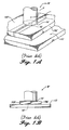
- One of the useful apparatus for FSW is shown in FIGURES 1A and 1B . As shown, two parts, exemplified by plates 10A', and 10B' are aligned so that edges of the plates to be welded together are held in direct contact on a backing plate 12'.
- An FSW tool W has a shoulder 14' at its distal end, and a non-consumable welding pin 16' extending downwards centrally from the shoulder.
- the rotating pin 16' As the rotating tool W' is brought into contact with the interface between plates 10B' and 10A', the rotating pin 16' is forced into contact with the material of both plates, as shown.
- the rotation of the pin in the material and rubbing of the shoulder against the upper surface of the material produces a large amount of frictional heating of both the welding tool and the plate interface. This heat softens the material of the plates in the vicinity of the rotating pin and shoulder, causing commingling of material, which upon hardening, forms a weld.
- the tool is moved longitudinally along the interface between plates 10A' and 10B', thereby forming an elongate weld all along the interface between the plates.
- the welding tool's shoulder 14' prevents softened material from the plates from escaping upwards, and forces the material into the weld joint. When the weld is completed, the welding tool is retracted.
- welds produced by the prior art friction stir welding process can produce smooth welds for certain materials, but for no-extrudable aluminum alloys, the maximum spindle speed is severely limited by adherence of the material to the welding tool shoulder and pin.
- these alloys exemplified by aluminum alloys 7075, 2014, 2090, and 2024, as the spindle speed increases, and correspondingly the heat input to the weld increases, the surface texture of the upper surface of the weld degrades by becoming rougher.
- the aluminum material adheres and builds up on the welding tool shoulder, tearing away material from the sides of the weld surface. For long welds, this condition can cause such excessive buildup that continuing the weld becomes impossible.
- the overheated welding tool can sometimes partially tear away surface material from the center of the weld surface, producing a "fish scale" appearance on the upper surface of the weld which progressively worsens along the length of the weld.
- a rough weld surface is undesirable, and requires additional machining to produce a smooth surface.
- Rough surfaces often provide points of initiation of fatigue cracks, and are therefore generally undesirable, especially if the welded part is to be used under conditions that could cause fatigue, such as cyclical conditions of applied load.
- FSW process that produces a weld of reduced surface roughness that would not require subsequent machining, for most applications, and that would have a uniform, smooth surface texture.
- the invention provides an apparatus for producing a friction stir weld of friction stir weldable materials, such as non-extrudable aluminum alloys, that has a smoother surface than heretofore achieved with conventional friction stir welding equipment.
- the weld is produced at higher speeds and has a commercially acceptable surface smoothness so that it does not require subsequent machining for most purposes.
- the invention provides apparatus for friction stir welding that are cooled by a coolant, distinguished by the features of claim 1 or 3.
- the coolant is circulated in the body of the tool to remove excess heat.
- the friction stir welding tool of the invention has a tool body with a rotatable, usually non-consumable, pin and shoulder at its distal end that are adapted for stir welding parts together.
- the tool body has an internal space that is in heat-conducting communication with the pin, and preferably also the shoulder, of the welding tool.
- the internal space is adapted for flowing a coolant therethrough to remove excess heat from the tool, including heat conducted from the shoulder and pin.
- heat is removed from the friction stir welding tool by a jacket that surrounds a distal portion of the tool body.
- the jacket has an inlet that is in fluid communication with a source of coolant, and an outlet for exit of heated coolant.
- the removal of heat is achieved by spraying a coolant (such as cold air, or a liquid coolant, such as water) onto the tool, and surrounding surfaces being welded, during the welding step.
- a coolant such as cold air, or a liquid coolant, such as water
- the tool portion being cooled is equipped with fins to facilitate heat removal.
- friction stir welds of even non-extrudable aluminum alloys are produced at commercially useful rates and have such a reduced surface roughness texture that they may be used commercially.
- a friction stir welding tool FSW
- a friction stir welding tool to reduce the degree of adherence between the tool and softened, difficult to weld material, such as non-extrudable aluminum alloys, so that a weld with a smoother surface is produced at a faster rate.
- Such smooth surface welds have many potential advantages, not only aesthetic, but also in reducing the risk of the initiation of fatigue cracking and corrosion.
- the production of such welds eliminates, or reduces, the need for costly further machining of the weld to produce a smooth surface.
- the invention also increases welding rate by allowing higher FSW tool rotational speeds.
- the apparatus of the invention is applicable to all kinds of material that are subject to friction stir welding, the invention is particularly useful when applied to materials that are difficult to friction stir weld, such as the non-extrudable aluminum alloys, exemplified by the 2024, 7075, 2014, and 2090 alloys. In the prior art, these alloys are typically welded at a much slower rate than the extrudable aluminum alloys, in order to produce a weld that extends throughout the workpiece, and that has a surface smoothness that is commercially acceptable, without need for subsequent machining.
- a one-quarter inch thick extrudable aluminum alloy such as alloy 6061
- a friction stir welding tool rotating at 1600 rpm, at a rate of 15 inches per minute
- a non-extrudable alloy would have to be welded at a lower tool rotation rate and slower rate of welding.
- a one-eighth inch thick non-extrudable alloy such as alloy 2024
- a tool rotation speed of about 500 rpm for a weld rate of 3.5 inches per minute. This produces a weld throughout the workpiece, that has a surface of acceptable smoothness, without need for subsequent machining.
- the same one-eighth inch thick workpiece of 2024 alloy can be welded at a tool rotation speed of at least about 800 rpm to produce a weld at a rate of about eight inches per minute, that extends throughout the workpiece and that has a commercially acceptable smooth surface.
- a one-eighth inch thick workpiece of 7075 aluminum alloy (a non-extrudable alloy)
- 7075 aluminum alloy can be welded with a tool rotating at 1100 rpm, and a welding rate of 13 inches per minute to produce a weld that extends throughout the workpiece, with a surface of acceptable smoothness without subsequent machining.
- the same 7075 alloy workpiece would have been welded with a tool rotating at 600 rpm and producing a weld at a rate of only seven inches per minute.
- the invention allows a significant increase in the rate of rotation of the friction stir welding tool, with a concomitant dramatic increase in the rate of welding, in inches per minute.
- the invention allows an increase in welding rate of at least about 20%, most preferably at least about 100%, while maintaining a weld surface smoothness that is usually commercially acceptable, without requiring subsequent machining, although such machining may optionally be performed for specific applications.
- the invention provides a range of apparatus for removing excess heat, and the preferred embodiments of these apparatus are illustrated in the accompanying FIGURES, for ease of explanation.
- FIGURES for ease of explanation.
- other apparatus that perform the same function, of removing excess heat, so that a smoother weld surface is produced at a faster rate, are also within the scope of the invention.
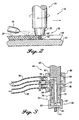
- FIGURE 2 a schematic side view of a preferred example of an apparatus, a substantially cylindrical weld tool body 30 having a proximal end 34, for operative connection to a drive motor for rotating the tool, and a distal end 36, that is equipped with a shoulder 38 and a substantially cylindrical pin 40 extending axially downward through a center of the shoulder.
- the pin 40 has a tip 42 and an outer surface that is helically grooved.
- the shoulder 38 is usually slightly peaked upward, from its circular periphery to the pin 40 at its center, at an angle of about 10°.
- a nozzle 50 extends in proximity to the welding tool body 30, in particular to the distal end 36, when a workpiece 20 is being welded on a backing plate 24.
- the rotating cylindrical pin has a tip 42 at its distal end that extends through the workpiece 20 to a depth to provide a minimal clearance between it and the backing plate 24.
- the pin extends substantially through the entire thickness of the workpiece 20, to produce a continuous weld 26 through the entire workpiece.
- the nozzle is in fluid communication with a source of coolant, such as a liquid or air, that is supplied under pressure to the nozzle, so that coolant exits the nozzle in a mist that impinges directly on the distal end 36 of the tool, and the surrounding workpiece 20.
- the coolant removes excess heat from both the exposed portion of the shoulder 38 that is above the workpiece 20 during welding, the workpiece 20 itself, and the weld 26 that is being formed. Heat travels by conduction from the hot rotating pin 40 and the shoulder 38 to their surroundings, namely, the workpiece 20 and the weld 26, from which the coolant then removes the heat. As a result, the temperatures of the surface of the rotating shoulder 38 and workpiece are significantly lower than would have been the case, but for the supply of coolant. These reduced surface temperatures caused by removal of excess heat, as explained above, provide a smoother weld surface at a faster weld rate.
- the amount of coolant should be controlled to avoid removal of so much heat as to interfere with the welding operation. A coolant rate of about 0.01 gpm is usually suitable and the rate may readily be optimized for a specific application.
- FIGURE 3 illustrates, schematically, in cross section, an internally cooled FSW tool in accordance with the invention.
- the substantially cylindrical tool body 60 has a proximal end 62 for coupling to a motor for rotating the tool, and a threaded distal end 64.
- a cap-shaped shoulder 66 with a circular shoulder base 65 and an internally threaded collar 67, is threadingly engaged to the distal end 64 of the FSW to produce an internal cylindrical space 74 between the base 63 of the tool body 60 and the base 65 of the shoulder.
- a pin preferably with a helically grooved exterior, extends downward from the center of the base of the shoulder.
- the tool includes an internal space, preferably a serpentine or tortuous internal space, that is in fluid communication with a source of coolant, and a sink for receiving heated coolant.
- the internal space is made up of vertical spaced and horizontal bores.
- a substantially horizontal inlet bore 70 penetrates to about the center of the distal end 64 of the cylindrical tool body 60.
- a central vertical bore 72 extends downward from the farthest extent of the horizontal bore 70 to exit from the base 63 of the distal end 64 of the tool body 60 so that it is in fluid communication with space 74.
- An annular space 76 concentric with the central bore 72, surrounds the central bore 72 and extends from the base 63 of the tool body 60 to below the inlet bore 70.
- the central bore 72 is in fluid communication with the annular space through internal space 74 at the very distal end 63 of the tool body 60.
- An exit bore 78 extends from an upper end of the annular space 76. Coolant fluid entering the inlet bore 70 flows down the central bore 72, into the internal cylindrical space 74, into the annular space 76 and out of the exit bore 78.
- a cylindrical coolant collar 80 In order to direct the coolant, a cylindrical coolant collar 80, concentric with and spaced from the tool body 60, surrounds the inlet 70 and outlet 78 bores.
- the collar 80 is sealed against the body 60 of the tool with an upper O-ring seal 82 above the inlet bore 70, and is also sealed against the tool body with a lower O-ring seal 84 below the exit bore 78.
- the collar 80 is sealed to the tool body 60 by a third O-ring 86 located between the inlet 70 and outlet 78 bores.
- the collar 80 forms a separate inlet compartment 90 that is in fluid communication with the inlet bore 70, and an outlet compartment 96 that is in fluid communication with the outlet bore 78.
- a coolant inlet hose 92 is coupled to the inlet compartment 90 of the collar, and a coolant outlet hose 98 is coupled to the outlet compartment 96 of the collar 80. Control of coolant flow is important to avoid overcooling of the tool thereby interfering with the welding process.
- a coolant rate of about 0.1 gallons per minute is suitable.
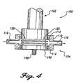
- FIGURE 4 An alternative embodiment, using an external cooling jacket, is illustrated schematically in FIGURE 4 .
- the cylindrical welding tool body 100 has a proximal end 102 adapted for coupling to a means for rotating the tool, and a distal end 104 equipped with a central downwardly extending pin 106, surrounded by a shoulder 108.
- the substantially cylindrical distal end 104 of the tool body 100 is equipped with an external structure designed to dissipate heat, in this instance a series of circumferentially extending fins 120. The structure increases the surface area of the distal end, i thereby permitting removal of larger amounts of heat for more effective cooling.
- a substantially cylindrical jacket 110 surrounds the finned distal end 104 of the tool 100, and is sealed against the tool body 100 by an upper O-ring 112, and a lower O-ring 114.
- the jacket 110 surrounds the fins 120, and is spaced from the fins to provide an annular region 122 that is in fluid communication with an inlet port 116 of the jacket, and an outlet port 118.
- coolant fluid enters the inlet port 116, flows into the annular space and around the fins 120, and exits from the outlet port 118, removing heat from the surface of the tool 100.
- the welding tool is cooled by using cold air as a coolant.
- the welding tool 100 is equipped with a series of circumferentially extending cooling fins 120 on its distal end 104.
- at least one nozzle 125 is oriented to continuously blast cold air, or another cold gas, onto the fins 120 of the welding tool to provide cooling.
- this removal of excess heat results in a cooler welding tool so that a weld with a uniform, smooth upper surface is produced, at a faster rate.
- a weld that is significantly smoother than achievable with prior art friction stir welding techniques and tools is produced.
- FIGURE 6A an optical micrograph of an aluminum alloy 2024 stir weld at magnification of eight times, a weld produced according to the prior art is rough, having open tears on its upper surface. The weld was produced at a FSW tool rotation speed of 640 rpm, and a weld rate of 6.3 inches per minute.
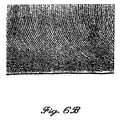
- FIGURE 6B an optical micrograph at the same magnification for the same material, has a uniform, smooth surface, without surface tears.
- This weld was produced by a FSW tool rotating at 640 rpm and welding at a rate of 6.3 inches per minute.
- the weld surface shown in FIGURE 6B was produced with an air/water mist applied at the junction between the tool shoulder and the weld surface, on the side opposite the direction of welding. It may be expected that this reduction in roughness will reduce the likelihood of fatigue crack initiation and surface corrosion and would therefore prolong the life (and safety) of welded parts. Also, it is expected that long welds could be performed without material buildup on the shoulder.
- any means-plus-function clauses are intended to cover the structures described herein as performing the recited function, and not only structural equivalents, but also equivalent structures.
- a nail and a screw may not be structural equivalents in that a nail employs a cylindrical surface to secure wooden parts together, whereas a screw employs a helical surface, in the environment of fastening wooden parts, a nail and a screw may nevertheless be equivalent structures.
Landscapes
- Engineering & Computer Science (AREA)
- Mechanical Engineering (AREA)
- Physics & Mathematics (AREA)
- Thermal Sciences (AREA)
- Pressure Welding/Diffusion-Bonding (AREA)
Priority Applications (1)
| Application Number | Priority Date | Filing Date | Title |
|---|---|---|---|
| DE69724326.5T DE69724326T3 (de) | 1996-05-31 | 1997-05-16 | Oszillierendes Reibrührschweissen mit simultaner Kühlung |
Applications Claiming Priority (2)
| Application Number | Priority Date | Filing Date | Title |
|---|---|---|---|
| US655926 | 1996-05-31 | ||
| US08/655,926 US6516992B1 (en) | 1996-05-31 | 1996-05-31 | Friction stir welding with simultaneous cooling |
Publications (4)
| Publication Number | Publication Date |
|---|---|
| EP0810056A2 EP0810056A2 (en) | 1997-12-03 |
| EP0810056A3 EP0810056A3 (en) | 1998-12-02 |
| EP0810056B1 EP0810056B1 (en) | 2003-08-27 |
| EP0810056B2 true EP0810056B2 (en) | 2014-05-21 |
Family
ID=24630960
Family Applications (1)
| Application Number | Title | Priority Date | Filing Date |
|---|---|---|---|
| EP97201482.3A Expired - Lifetime EP0810056B2 (en) | 1996-05-31 | 1997-05-16 | Friction stir welding with simultaneous cooling |
Country Status (7)
| Country | Link |
|---|---|
| US (1) | US6516992B1 (ja) |
| EP (1) | EP0810056B2 (ja) |
| JP (1) | JP3530342B2 (ja) |
| KR (1) | KR100492837B1 (ja) |
| CN (1) | CN1084654C (ja) |
| CA (1) | CA2204570C (ja) |
| DE (1) | DE69724326T3 (ja) |
Families Citing this family (109)
| Publication number | Priority date | Publication date | Assignee | Title |
|---|---|---|---|---|
| JP3589863B2 (ja) | 1997-07-23 | 2004-11-17 | 株式会社日立製作所 | 構造体および摩擦攪拌接合方法 |
| KR19990083213A (ko) * | 1998-04-16 | 1999-11-25 | 구마모토 마사히로 | 진공챔버부재와 그 제조방법 |
| US6053391A (en) * | 1998-05-14 | 2000-04-25 | Tower Automotive, Inc. | Friction stir welding tool |
| US6045028A (en) * | 1998-07-17 | 2000-04-04 | Mcdonnell Douglas Corporation | Integral corrosion protection of friction-welded joints |
| NL1011908C1 (nl) * | 1999-04-27 | 2000-10-30 | Fokker Aerostructures Bv | Wrijvingsroerlassen. |
| GB0010793D0 (en) * | 2000-05-03 | 2000-06-28 | Boc Group Plc | Improvements in thermal welding |
| EP1345729B1 (en) | 2000-05-08 | 2008-07-09 | Brigham Young University | Friction stir welding using a superabrasive tool |
| DE10035332C1 (de) * | 2000-07-20 | 2002-02-28 | Eads Deutschland Gmbh | Verfahren und Vorrichtung zum Reibrührschweißen |
| US6352193B1 (en) | 2000-08-01 | 2002-03-05 | General Electric Company | Apparatus for joining electrically conductive materials |
| JP4809521B2 (ja) * | 2000-09-19 | 2011-11-09 | マンヨーツール株式会社 | 工具ホルダ及びその冷却装置 |
| JP3818084B2 (ja) * | 2000-12-22 | 2006-09-06 | 日立電線株式会社 | 冷却板とその製造方法及びスパッタリングターゲットとその製造方法 |
| US6676004B1 (en) * | 2001-02-13 | 2004-01-13 | Edison Welding Institute, Inc. | Tool for friction stir welding |
| US6732901B2 (en) | 2001-06-12 | 2004-05-11 | Brigham Young University Technology Transfer Office | Anvil for friction stir welding high temperature materials |
| DE10139687C1 (de) * | 2001-08-11 | 2003-02-20 | Eads Deutschland Gmbh | Reibrührwerkzeug zum Reibschweißen |
| SE522075C2 (sv) * | 2001-10-23 | 2004-01-13 | Svensk Kaernbraenslehantering | Förfarande för friktionsomröringssvetsning |
| US6780525B2 (en) * | 2001-12-26 | 2004-08-24 | The Boeing Company | High strength friction stir welding |
| JP4536992B2 (ja) * | 2002-03-20 | 2010-09-01 | 川崎重工業株式会社 | スポット接合方法 |
| US6908690B2 (en) * | 2002-04-29 | 2005-06-21 | The Boeing Company | Method and apparatus for friction stir welding |
| US7225966B2 (en) * | 2002-08-07 | 2007-06-05 | Eclipse Aviation Corporation | Welded joints with polymer sealant |
| US6776328B2 (en) * | 2002-09-17 | 2004-08-17 | The Boeing Company | Radiation assisted friction welding |
| EP1606074A4 (en) | 2003-01-30 | 2008-08-27 | Smith International | FRICTION WELDING OFF-POSITION MIXING OF FUSION HIGH TEMPERATURE ALLOYS |
| WO2004091839A2 (en) * | 2003-04-11 | 2004-10-28 | Edison Welding Institute | Method and apparatus for locally clamping components that are to be joined by friction stir welding |
| US7530486B2 (en) | 2003-05-05 | 2009-05-12 | Sii Megadiamond, Inc. | Applications of friction stir welding using a superabrasive tool |
| EP1667811A4 (en) | 2003-08-04 | 2008-08-27 | Sii Megadiamond Inc | CRACK REPAIR USING AGITATION FRICTION WELDING ON MATERIALS COMPRISING METAL MATRIX COMPOSITES, FERROUS ALLOYS, NON-FERROUS ALLOYS AND SUPERALLIAGES |
| JP2005074451A (ja) * | 2003-08-29 | 2005-03-24 | Toyota Motor Corp | 摩擦攪拌接合方法及び摩擦攪拌接合装置 |
| US7121448B2 (en) * | 2003-08-29 | 2006-10-17 | General Electric Company | Friction stir welding apparatus and associated thermal management systems and methods |
| US6913186B2 (en) | 2003-09-11 | 2005-07-05 | The Boeing Company | Apparatus and method for friction stir welding with a variable speed pin |
| US6994242B2 (en) | 2003-12-09 | 2006-02-07 | The Boeing Company | Friction stir weld tool and method |
| US7398911B2 (en) * | 2003-12-16 | 2008-07-15 | The Boeing Company | Structural assemblies and preforms therefor formed by friction welding |
| US7225967B2 (en) | 2003-12-16 | 2007-06-05 | The Boeing Company | Structural assemblies and preforms therefor formed by linear friction welding |
| JP4085988B2 (ja) * | 2004-02-20 | 2008-05-14 | マツダ株式会社 | 摩擦接合装置の回転ツール |
| WO2005094274A2 (en) | 2004-03-24 | 2005-10-13 | Smith International, Inc. | Solid state processing of hand-held knife blades to improve blade performance |
| GB2452885B (en) * | 2004-04-30 | 2009-04-22 | Tokyu Car Corp | Method of connecting metal material |
| US20100078224A1 (en) | 2004-05-21 | 2010-04-01 | Smith International, Inc. | Ball hole welding using the friction stir welding (fsw) process |
| US7275675B1 (en) | 2004-08-20 | 2007-10-02 | United States Of America As Represented By The Administrator Of The National Aeronautics And Space Administration | Friction stir weld tools |
| US7383975B2 (en) * | 2004-08-30 | 2008-06-10 | Alcoa Inc. | Fracture resistant friction stir welding tools |
| US7401723B2 (en) * | 2004-08-30 | 2008-07-22 | Alcoa Inc. | Advanced friction stir welding tools |
| US7198189B2 (en) * | 2004-09-28 | 2007-04-03 | Alcoa Inc. | Multi-shouldered fixed bobbin tools for simultaneous friction stir welding of multiple parallel walls between parts |
| KR101148275B1 (ko) | 2004-10-05 | 2012-05-21 | 어드밴스드 메탈 프로덕츠, 아이엔씨. | 마찰교반용접에 사용하기 위한 연장 가능한 맨드릴 |
| DE102005029882A1 (de) * | 2005-06-27 | 2006-12-28 | Gkss-Forschungszentrum Geesthacht Gmbh | Vorrichtung zum Reibrührschweißen |
| US7497917B2 (en) * | 2005-08-31 | 2009-03-03 | Gm Global Technology Operations, Inc. | Friction heating for joining dissimilar materials |
| US7508682B2 (en) * | 2005-09-19 | 2009-03-24 | Hitachi, Ltd. | Housing for an electronic circuit |
| US9266191B2 (en) | 2013-12-18 | 2016-02-23 | Aeroprobe Corporation | Fabrication of monolithic stiffening ribs on metallic sheets |
| US8397974B2 (en) | 2005-09-26 | 2013-03-19 | Aeroprobe Corporation | Self-reacting friction stir welding tool with the ability to add filler material |
| US9511445B2 (en) | 2014-12-17 | 2016-12-06 | Aeroprobe Corporation | Solid state joining using additive friction stir processing |
| US20080041921A1 (en) | 2005-09-26 | 2008-02-21 | Kevin Creehan | Friction stir fabrication |
| US9511446B2 (en) | 2014-12-17 | 2016-12-06 | Aeroprobe Corporation | In-situ interlocking of metals using additive friction stir processing |
| US8875976B2 (en) | 2005-09-26 | 2014-11-04 | Aeroprobe Corporation | System for continuous feeding of filler material for friction stir welding, processing and fabrication |
| US8632850B2 (en) | 2005-09-26 | 2014-01-21 | Schultz-Creehan Holdings, Inc. | Friction fabrication tools |
| US8056797B2 (en) | 2005-10-05 | 2011-11-15 | Megastir Technologies | Expandable mandrel for use in friction stir welding |
| US8550326B2 (en) | 2005-10-05 | 2013-10-08 | Megastir Technologies Llc | Expandable mandrel for use in friction stir welding |
| JP4327788B2 (ja) * | 2005-11-08 | 2009-09-09 | 本田技研工業株式会社 | 摩擦攪拌接合方法 |
| JP4768418B2 (ja) * | 2005-11-28 | 2011-09-07 | 川崎重工業株式会社 | 摩擦撹拌接合方法 |
| JP2007237282A (ja) * | 2006-03-10 | 2007-09-20 | Osaka Univ | 金属材の接合方法 |
| JP4861038B2 (ja) * | 2006-03-31 | 2012-01-25 | 東急車輛製造株式会社 | アダプタ、アダプタの冷却方法及び摩擦撹拌接合方法 |
| GB0609669D0 (en) * | 2006-05-15 | 2006-06-28 | Welding Inst | Friction stir method |
| ITBO20060415A1 (it) * | 2006-05-26 | 2007-11-27 | Pei Protezioni Elaborazioni | Dispositivo aspirante per macchine utensili, di saldatura, operatrici e simili |
| US20080217377A1 (en) * | 2007-03-06 | 2008-09-11 | Alcoa Inc. | Fracture Resistant Friction Stir Welding Tool |
| CN100460131C (zh) * | 2007-04-24 | 2009-02-11 | 中国航空工业第一集团公司北京航空制造工程研究所 | 阵列式射流冲击热沉搅拌摩擦焊接方法及装置 |
| TW200932421A (en) * | 2007-08-31 | 2009-08-01 | Air Turbine Tech Inc | Apparatus and method for machining |
| US7793816B2 (en) * | 2007-09-07 | 2010-09-14 | Alcoa Inc. | Friction stir welding apparatus |
| US7854362B2 (en) * | 2008-03-14 | 2010-12-21 | Alcoa Inc. | Advanced multi-shouldered fixed bobbin tools for simultaneous friction stir welding of multiple parallel walls between parts |
| FR2933016B1 (fr) * | 2008-06-30 | 2010-12-24 | Alcan Rhenalu | Procede de soudage par friction malaxage pulse |
| US20100038405A1 (en) * | 2008-08-13 | 2010-02-18 | Garner Timothy D | Spindle-integrated cooling and collection device for stir friction welder |
| CN101660032B (zh) * | 2009-09-07 | 2011-04-13 | 重庆大学 | 一种熔化焊接头表面处理方法 |
| JP2013509301A (ja) | 2009-11-02 | 2013-03-14 | メガスター・テクノロジーズ・エルエルシー | ケーシングおよび小径管類または小径パイプの位置ずれ摩擦攪拌溶接 |
| DE102009046816A1 (de) * | 2009-11-18 | 2011-05-19 | Robert Bosch Gmbh | Verfahren zur Schweißvorbereitung zweier Kunststoff-Bauteile |
| EP2338632A1 (de) * | 2009-12-22 | 2011-06-29 | Harms & Wende GmbH & Co. KG | Reibpunktschweisswerkzeug |
| US8141764B1 (en) | 2010-04-06 | 2012-03-27 | United Launch Alliance, Llc | Friction stir welding apparatus, system and method |
| US7866532B1 (en) | 2010-04-06 | 2011-01-11 | United Launch Alliance, Llc | Friction stir welding apparatus, system and method |
| US8123104B1 (en) | 2010-04-06 | 2012-02-28 | United Launch Alliance, Llc | Friction welding apparatus, system and method |
| JP2013542076A (ja) * | 2010-09-23 | 2013-11-21 | テクナラ エフエスダブリュ カンパニー, エルエルシー | 高速摩擦スポット接合ツールを保持する方法 |
| CN102811833B (zh) | 2010-10-08 | 2016-04-27 | 住友轻金属工业株式会社 | 铝合金接合部件 |
| JP5937967B2 (ja) | 2010-11-04 | 2016-06-22 | 株式会社Ihi | 摩擦撹拌接合装置 |
| RU2446926C1 (ru) * | 2010-11-18 | 2012-04-10 | Открытое акционерное общество "Национальный институт авиационных технологий" (ОАО "НИАТ") | Инструмент для фрикционной сварки перемешиванием |
| CN102528268B (zh) * | 2010-12-17 | 2014-05-07 | 中国科学院金属研究所 | 一种增强接头力学性能的搅拌摩擦焊接工艺 |
| JP5461476B2 (ja) * | 2011-05-27 | 2014-04-02 | 三菱重工業株式会社 | 摩擦攪拌接合装置 |
| CN103157893A (zh) * | 2011-12-16 | 2013-06-19 | 宝山钢铁股份有限公司 | 正面同步水冷焊缝的焊接方法及装置 |
| CN102615419B (zh) * | 2012-04-06 | 2014-04-16 | 江苏科技大学 | 一种搅拌摩擦焊缝干式冷却装置及冷却方法 |
| RU2517653C1 (ru) * | 2012-12-20 | 2014-05-27 | Михаил Михайлович Штрикман | Инструмент для фрикционной сварки перемешиванием |
| CN103639588B (zh) * | 2013-11-11 | 2015-10-07 | 江苏科技大学 | 一种用于搅拌摩擦焊的固态热沉装置及其焊接方法 |
| US9010613B1 (en) | 2013-12-16 | 2015-04-21 | The Boeing Company | Apparatus for friction stir welding |
| US20160355902A1 (en) * | 2014-01-20 | 2016-12-08 | GM Global Technology Operations LLC | Welding method and system |
| CN104070287B (zh) * | 2014-04-30 | 2016-05-18 | 燕山大学 | 一种抑制高强铝合金搅拌摩擦焊接头软化的方法及装置 |
| CN104014926B (zh) * | 2014-05-30 | 2016-08-17 | 北京赛福斯特技术有限公司 | 无倾角自顶锻搅拌摩擦焊焊接方法及工具 |
| DE102014010058B4 (de) | 2014-07-07 | 2016-01-28 | Grenzebach Maschinenbau Gmbh | Verfahren und Vorrichtung zum schnellen und sicheren Werkzeugwechsel bei dem Vorgang des Rührreibschweißens und ein Computerprogramm zur Durchführung des Verfahrens |
| ES2651500T3 (es) * | 2015-03-18 | 2018-01-26 | Helmholtz-Zentrum Geesthacht Zentrum für Material- und Küstenforschung GmbH | Aparato para soldar por fricción-agitación con un resalte que comprende agujeros pasantes primero y segundo |
| RU2603341C1 (ru) * | 2015-04-29 | 2016-11-27 | Михаил Михайлович Штрикман | Обрабатывающий инструмент с устройством для охлаждения |
| US10086396B2 (en) * | 2016-03-28 | 2018-10-02 | Nazila Sedaei | Electro-anti deposit device for removing mineral deposits in drip irrigation systems |
| JP6143915B1 (ja) * | 2016-04-28 | 2017-06-07 | 株式会社日立パワーソリューションズ | 摩擦攪拌接合装置 |
| CN106181017A (zh) * | 2016-07-11 | 2016-12-07 | 中国船舶重工集团公司第七二五研究所 | 一种铜镍合金的搅拌摩擦焊接方法 |
| US10279423B2 (en) * | 2016-08-17 | 2019-05-07 | The Boeing Company | Apparatuses and methods for fabricating metal matrix composite structures |
| MX2019001835A (es) * | 2016-08-22 | 2019-05-15 | Novelis Inc | Componentes y sistemas para soldadura por friccion-agitacion y procesos relacionados. |
| CN106735856A (zh) * | 2017-02-23 | 2017-05-31 | 江苏科技大学 | 一种搅拌摩擦头水冷装置及方法 |
| US11549157B2 (en) * | 2017-07-19 | 2023-01-10 | Shiv Nadar University | Method for modifying surface grain structure of the material and apparatus thereof |
| US11130192B2 (en) * | 2017-08-30 | 2021-09-28 | Mazak Corporation | Instrumented tool handler for friction stir welding |
| US11311959B2 (en) | 2017-10-31 | 2022-04-26 | MELD Manufacturing Corporation | Solid-state additive manufacturing system and material compositions and structures |
| CN108655668B (zh) * | 2018-04-28 | 2020-06-19 | 武汉理工大学 | 铝合金拼焊板成形加工工艺 |
| CN108772667A (zh) * | 2018-06-20 | 2018-11-09 | 辽宁忠旺集团有限公司 | 一种轨道车体用铝合金薄板的搅拌摩擦焊接方法 |
| CN108788447A (zh) * | 2018-08-09 | 2018-11-13 | 湖南文理学院 | 一种轨道移动式搅拌摩擦焊接设备 |
| RU2686494C1 (ru) * | 2018-10-12 | 2019-04-29 | Закрытое акционерное общество "Чебоксарское предприятие "Сеспель" | Способ сварки трением с перемешиванием стыковых соединений алюминиевых сплавов |
| CN111438434B (zh) * | 2020-05-15 | 2021-07-09 | 沈阳飞机工业(集团)有限公司 | 基于冷-热拉伸的搅拌摩擦薄板胶焊方法 |
| KR102231384B1 (ko) * | 2020-09-02 | 2021-03-24 | 주식회사 태강기업 | 마찰 용접기 |
| RU2746930C1 (ru) * | 2020-10-23 | 2021-04-22 | Закрытое Акционерное Общество "Чебоксарское Предприятие "Сеспель" (ЗАО "Чебоксарское Предприятие "Сеспель") | Устройство и инструмент для сварки трением с перемешиванием преимущественно листовых заготовок из титана и его сплавов |
| FR3122110B1 (fr) * | 2021-04-22 | 2023-07-21 | Inst Maupertuis | Electrobroche équipée d’un circuit de refroidissement |
| US11660700B2 (en) | 2021-06-04 | 2023-05-30 | Dus Operating Inc. | Welding and deburring system with cryogenic cooling |
| CN113319599B (zh) * | 2021-07-09 | 2023-01-17 | 重庆市超群工业股份有限公司 | 汽车轮毂加工系统 |
| CN113967783B (zh) * | 2021-10-22 | 2022-08-02 | 南京工业大学 | 一种同轴喷雾冷却耦合辅助fsw的装置及使用方法 |
| WO2024034268A1 (ja) * | 2022-08-08 | 2024-02-15 | 国立大学法人大阪大学 | 摩擦攪拌接合方法及び摩擦攪拌接合用ツール |
Citations (6)
| Publication number | Priority date | Publication date | Assignee | Title |
|---|---|---|---|---|
| GB591201A (en) † | 1944-05-02 | 1947-08-11 | Mallory Metallurg Prod Ltd | Improvements in or relating to welding electrode cooling |
| US3234643A (en) † | 1962-05-24 | 1966-02-15 | American Mach & Foundry | Friction welding |
| US3717539A (en) † | 1968-05-27 | 1973-02-20 | E Systems Inc | Ultrasonic welding apparatus |
| US4106167A (en) † | 1970-10-23 | 1978-08-15 | Penelope Jane Vesey Luc | Frictional method and machine for seaming tubular sections |
| US5248868A (en) † | 1992-05-22 | 1993-09-28 | Cusick Iii Joseph B | Melding gun |
| WO1995026254A1 (en) † | 1994-03-28 | 1995-10-05 | The Welding Institute | Friction stir welding |
Family Cites Families (6)
| Publication number | Priority date | Publication date | Assignee | Title |
|---|---|---|---|---|
| US3212182A (en) * | 1962-05-24 | 1965-10-19 | American Mach & Foundry | Friction welding |
| JPS51110455A (en) | 1975-03-25 | 1976-09-30 | Maruma Tractor & Equip | Junkatsuzaifunyugatatoratsukurinkuno nikumoryosetsuhoho oyobi sonoreikyakuhogosochi |
| FR2659038B1 (fr) * | 1990-03-02 | 1994-11-10 | Snecma | Procede de soudage par friction et machine de mise en óoeuvre. |
| US5138766A (en) * | 1990-04-26 | 1992-08-18 | Fuji Photo Equipment Co., Ltd. | Roller for transporting sheet-like material and method for manufacturing the same |
| GB9125978D0 (en) | 1991-12-06 | 1992-02-05 | Welding Inst | Hot shear butt welding |
| GB2306366A (en) * | 1995-10-20 | 1997-05-07 | Welding Inst | Friction stir welding |
-
1996
- 1996-05-31 US US08/655,926 patent/US6516992B1/en not_active Expired - Lifetime
-
1997
- 1997-05-06 CA CA002204570A patent/CA2204570C/en not_active Expired - Lifetime
- 1997-05-16 EP EP97201482.3A patent/EP0810056B2/en not_active Expired - Lifetime
- 1997-05-16 DE DE69724326.5T patent/DE69724326T3/de not_active Expired - Lifetime
- 1997-05-26 JP JP13495497A patent/JP3530342B2/ja not_active Expired - Lifetime
- 1997-05-28 CN CN97113488A patent/CN1084654C/zh not_active Expired - Lifetime
- 1997-05-30 KR KR1019970022167A patent/KR100492837B1/ko active IP Right Grant
Patent Citations (6)
| Publication number | Priority date | Publication date | Assignee | Title |
|---|---|---|---|---|
| GB591201A (en) † | 1944-05-02 | 1947-08-11 | Mallory Metallurg Prod Ltd | Improvements in or relating to welding electrode cooling |
| US3234643A (en) † | 1962-05-24 | 1966-02-15 | American Mach & Foundry | Friction welding |
| US3717539A (en) † | 1968-05-27 | 1973-02-20 | E Systems Inc | Ultrasonic welding apparatus |
| US4106167A (en) † | 1970-10-23 | 1978-08-15 | Penelope Jane Vesey Luc | Frictional method and machine for seaming tubular sections |
| US5248868A (en) † | 1992-05-22 | 1993-09-28 | Cusick Iii Joseph B | Melding gun |
| WO1995026254A1 (en) † | 1994-03-28 | 1995-10-05 | The Welding Institute | Friction stir welding |
Non-Patent Citations (1)
| Title |
|---|
| Dawes C J et al: Friction Stir Process welds Aluminum Alloys (01.03.1996) † |
Also Published As
| Publication number | Publication date |
|---|---|
| CN1084654C (zh) | 2002-05-15 |
| DE69724326T3 (de) | 2014-08-14 |
| EP0810056A3 (en) | 1998-12-02 |
| JP3530342B2 (ja) | 2004-05-24 |
| DE69724326T2 (de) | 2004-02-19 |
| CA2204570A1 (en) | 1997-11-30 |
| CA2204570C (en) | 2005-07-12 |
| EP0810056A2 (en) | 1997-12-03 |
| CN1167663A (zh) | 1997-12-17 |
| KR970073845A (ko) | 1997-12-10 |
| EP0810056B1 (en) | 2003-08-27 |
| JPH1052770A (ja) | 1998-02-24 |
| US6516992B1 (en) | 2003-02-11 |
| DE69724326D1 (de) | 2003-10-02 |
| KR100492837B1 (ko) | 2005-09-02 |
Similar Documents
| Publication | Publication Date | Title |
|---|---|---|
| EP0810056B2 (en) | Friction stir welding with simultaneous cooling | |
| KR100492835B1 (ko) | 마찰교반용접공구및방법 | |
| US7832613B2 (en) | Friction stir welding system | |
| EP1077787B1 (en) | Friction stir welding tool | |
| CA2182719C (en) | Friction stir welding | |
| US20090123778A1 (en) | Friction stir method and a pair of workpieces joint by such method | |
| EP1029627B1 (en) | Friction agitation jointing method of metal workpieces | |
| US6892924B2 (en) | Precessing rivet and method for friction stir riveting | |
| TWI538758B (zh) | 攪拌摩擦補焊工藝及採用該補焊工藝之攪拌摩擦焊接方法 | |
| EP1438154A1 (en) | Method for friction stir welding | |
| JP2002028792A (ja) | 熱溶接における改善 | |
| US20050224562A1 (en) | Apparatus and method for forming a weld joint having improved physical properties | |
| CN211305187U (zh) | 一种用于摩擦焊的旋转焊具 | |
| Raturi et al. | Appraising tool wear during secondary heating assisted dissimilar friction stir welding between 6061 and 7075 aluminium alloys | |
| Zhi-Hong et al. | Friction stir welding of aluminum alloys | |
| JP2000225476A (ja) | 金属製ワーク同士の摩擦撹拌接合方法 | |
| CN220591876U (zh) | 一种自发热的搅拌摩擦工具 | |
| CN110129792B (zh) | 全液态搅拌与半固态搅拌涂覆法制备复合管/涂层的方法及装置 | |
| Balanovsky et al. | Friction welding with stirring of aluminium alloys AMg-5 | |
| Nunes | Friction stir welding | |
| Abd El-Nasser et al. | Effect of the friction stir welding parameters on the mechanical properties of Al 5083 joint | |
| Gerçekcioglu et al. | BALKANTRIB’O5 5 th INTERNATIONAL CONFERENCE ON TRIBOLOGY JUNE. 15-18. 2005 |
Legal Events
| Date | Code | Title | Description |
|---|---|---|---|
| PUAI | Public reference made under article 153(3) epc to a published international application that has entered the european phase |
Free format text: ORIGINAL CODE: 0009012 |
|
| AK | Designated contracting states |
Kind code of ref document: A2 Designated state(s): DE FR GB SE |
|
| PUAL | Search report despatched |
Free format text: ORIGINAL CODE: 0009013 |
|
| AK | Designated contracting states |
Kind code of ref document: A3 Designated state(s): DE FR GB SE |
|
| 17P | Request for examination filed |
Effective date: 19990507 |
|
| 17Q | First examination report despatched |
Effective date: 20020225 |
|
| GRAH | Despatch of communication of intention to grant a patent |
Free format text: ORIGINAL CODE: EPIDOS IGRA |
|
| GRAH | Despatch of communication of intention to grant a patent |
Free format text: ORIGINAL CODE: EPIDOS IGRA |
|
| GRAA | (expected) grant |
Free format text: ORIGINAL CODE: 0009210 |
|
| REG | Reference to a national code |
Ref country code: SE Ref legal event code: TRGR |
|
| AK | Designated contracting states |
Designated state(s): DE FR GB SE |
|
| REG | Reference to a national code |
Ref country code: GB Ref legal event code: FG4D |
|
| REF | Corresponds to: |
Ref document number: 69724326 Country of ref document: DE Date of ref document: 20031002 Kind code of ref document: P |
|
| ET | Fr: translation filed | ||
| PLBQ | Unpublished change to opponent data |
Free format text: ORIGINAL CODE: EPIDOS OPPO |
|
| PLBI | Opposition filed |
Free format text: ORIGINAL CODE: 0009260 |
|
| PLAX | Notice of opposition and request to file observation + time limit sent |
Free format text: ORIGINAL CODE: EPIDOSNOBS2 |
|
| 26 | Opposition filed |
Opponent name: AIRBUS SAS Effective date: 20040527 |
|
| PLAX | Notice of opposition and request to file observation + time limit sent |
Free format text: ORIGINAL CODE: EPIDOSNOBS2 |
|
| PLBB | Reply of patent proprietor to notice(s) of opposition received |
Free format text: ORIGINAL CODE: EPIDOSNOBS3 |
|
| APBP | Date of receipt of notice of appeal recorded |
Free format text: ORIGINAL CODE: EPIDOSNNOA2O |
|
| APAH | Appeal reference modified |
Free format text: ORIGINAL CODE: EPIDOSCREFNO |
|
| APBP | Date of receipt of notice of appeal recorded |
Free format text: ORIGINAL CODE: EPIDOSNNOA2O |
|
| APBQ | Date of receipt of statement of grounds of appeal recorded |
Free format text: ORIGINAL CODE: EPIDOSNNOA3O |
|
| APBQ | Date of receipt of statement of grounds of appeal recorded |
Free format text: ORIGINAL CODE: EPIDOSNNOA3O |
|
| APBU | Appeal procedure closed |
Free format text: ORIGINAL CODE: EPIDOSNNOA9O |
|
| PLAY | Examination report in opposition despatched + time limit |
Free format text: ORIGINAL CODE: EPIDOSNORE2 |
|
| PLBC | Reply to examination report in opposition received |
Free format text: ORIGINAL CODE: EPIDOSNORE3 |
|
| APBM | Appeal reference recorded |
Free format text: ORIGINAL CODE: EPIDOSNREFNO |
|
| APBP | Date of receipt of notice of appeal recorded |
Free format text: ORIGINAL CODE: EPIDOSNNOA2O |
|
| APAH | Appeal reference modified |
Free format text: ORIGINAL CODE: EPIDOSCREFNO |
|
| APBQ | Date of receipt of statement of grounds of appeal recorded |
Free format text: ORIGINAL CODE: EPIDOSNNOA3O |
|
| APBU | Appeal procedure closed |
Free format text: ORIGINAL CODE: EPIDOSNNOA9O |
|
| PUAH | Patent maintained in amended form |
Free format text: ORIGINAL CODE: 0009272 |
|
| STAA | Information on the status of an ep patent application or granted ep patent |
Free format text: STATUS: PATENT MAINTAINED AS AMENDED |
|
| 27A | Patent maintained in amended form |
Effective date: 20140521 |
|
| AK | Designated contracting states |
Kind code of ref document: B2 Designated state(s): DE FR GB SE |
|
| REG | Reference to a national code |
Ref country code: DE Ref legal event code: R102 Ref document number: 69724326 Country of ref document: DE |
|
| REG | Reference to a national code |
Ref country code: DE Ref legal event code: R102 Ref document number: 69724326 Country of ref document: DE Effective date: 20140521 |
|
| REG | Reference to a national code |
Ref country code: SE Ref legal event code: RPEO |
|
| REG | Reference to a national code |
Ref country code: FR Ref legal event code: PLFP Year of fee payment: 20 |
|
| PGFP | Annual fee paid to national office [announced via postgrant information from national office to epo] |
Ref country code: GB Payment date: 20160527 Year of fee payment: 20 Ref country code: DE Payment date: 20160527 Year of fee payment: 20 |
|
| PGFP | Annual fee paid to national office [announced via postgrant information from national office to epo] |
Ref country code: SE Payment date: 20160527 Year of fee payment: 20 Ref country code: FR Payment date: 20160530 Year of fee payment: 20 |
|
| REG | Reference to a national code |
Ref country code: DE Ref legal event code: R071 Ref document number: 69724326 Country of ref document: DE |
|
| REG | Reference to a national code |
Ref country code: GB Ref legal event code: PE20 Expiry date: 20170515 |
|
| REG | Reference to a national code |
Ref country code: SE Ref legal event code: EUG |
|
| PG25 | Lapsed in a contracting state [announced via postgrant information from national office to epo] |
Ref country code: GB Free format text: LAPSE BECAUSE OF EXPIRATION OF PROTECTION Effective date: 20170515 |