EP0810056A2 - Friction stir welding with simultaneous cooling - Google Patents
Friction stir welding with simultaneous cooling Download PDFInfo
- Publication number
- EP0810056A2 EP0810056A2 EP97201482A EP97201482A EP0810056A2 EP 0810056 A2 EP0810056 A2 EP 0810056A2 EP 97201482 A EP97201482 A EP 97201482A EP 97201482 A EP97201482 A EP 97201482A EP 0810056 A2 EP0810056 A2 EP 0810056A2
- Authority
- EP
- European Patent Office
- Prior art keywords
- tool
- coolant
- weld
- welding
- friction stir
- Prior art date
- Legal status (The legal status is an assumption and is not a legal conclusion. Google has not performed a legal analysis and makes no representation as to the accuracy of the status listed.)
- Granted
Links
Images


Classifications
-
- B—PERFORMING OPERATIONS; TRANSPORTING
- B29—WORKING OF PLASTICS; WORKING OF SUBSTANCES IN A PLASTIC STATE IN GENERAL
- B29C—SHAPING OR JOINING OF PLASTICS; SHAPING OF MATERIAL IN A PLASTIC STATE, NOT OTHERWISE PROVIDED FOR; AFTER-TREATMENT OF THE SHAPED PRODUCTS, e.g. REPAIRING
- B29C65/00—Joining or sealing of preformed parts, e.g. welding of plastics materials; Apparatus therefor
- B29C65/02—Joining or sealing of preformed parts, e.g. welding of plastics materials; Apparatus therefor by heating, with or without pressure
- B29C65/06—Joining or sealing of preformed parts, e.g. welding of plastics materials; Apparatus therefor by heating, with or without pressure using friction, e.g. spin welding
- B29C65/0681—Joining or sealing of preformed parts, e.g. welding of plastics materials; Apparatus therefor by heating, with or without pressure using friction, e.g. spin welding created by a tool
-
- B—PERFORMING OPERATIONS; TRANSPORTING
- B23—MACHINE TOOLS; METAL-WORKING NOT OTHERWISE PROVIDED FOR
- B23K—SOLDERING OR UNSOLDERING; WELDING; CLADDING OR PLATING BY SOLDERING OR WELDING; CUTTING BY APPLYING HEAT LOCALLY, e.g. FLAME CUTTING; WORKING BY LASER BEAM
- B23K20/00—Non-electric welding by applying impact or other pressure, with or without the application of heat, e.g. cladding or plating
- B23K20/12—Non-electric welding by applying impact or other pressure, with or without the application of heat, e.g. cladding or plating the heat being generated by friction; Friction welding
- B23K20/122—Non-electric welding by applying impact or other pressure, with or without the application of heat, e.g. cladding or plating the heat being generated by friction; Friction welding using a non-consumable tool, e.g. friction stir welding
- B23K20/123—Controlling or monitoring the welding process
- B23K20/1235—Controlling or monitoring the welding process with temperature control during joining
-
- B—PERFORMING OPERATIONS; TRANSPORTING
- B23—MACHINE TOOLS; METAL-WORKING NOT OTHERWISE PROVIDED FOR
- B23K—SOLDERING OR UNSOLDERING; WELDING; CLADDING OR PLATING BY SOLDERING OR WELDING; CUTTING BY APPLYING HEAT LOCALLY, e.g. FLAME CUTTING; WORKING BY LASER BEAM
- B23K20/00—Non-electric welding by applying impact or other pressure, with or without the application of heat, e.g. cladding or plating
- B23K20/12—Non-electric welding by applying impact or other pressure, with or without the application of heat, e.g. cladding or plating the heat being generated by friction; Friction welding
- B23K20/122—Non-electric welding by applying impact or other pressure, with or without the application of heat, e.g. cladding or plating the heat being generated by friction; Friction welding using a non-consumable tool, e.g. friction stir welding
- B23K20/1245—Non-electric welding by applying impact or other pressure, with or without the application of heat, e.g. cladding or plating the heat being generated by friction; Friction welding using a non-consumable tool, e.g. friction stir welding characterised by the apparatus
- B23K20/1255—Tools therefor, e.g. characterised by the shape of the probe
-
- B—PERFORMING OPERATIONS; TRANSPORTING
- B29—WORKING OF PLASTICS; WORKING OF SUBSTANCES IN A PLASTIC STATE IN GENERAL
- B29C—SHAPING OR JOINING OF PLASTICS; SHAPING OF MATERIAL IN A PLASTIC STATE, NOT OTHERWISE PROVIDED FOR; AFTER-TREATMENT OF THE SHAPED PRODUCTS, e.g. REPAIRING
- B29C66/00—General aspects of processes or apparatus for joining preformed parts
- B29C66/01—General aspects dealing with the joint area or with the area to be joined
- B29C66/05—Particular design of joint configurations
- B29C66/10—Particular design of joint configurations particular design of the joint cross-sections
- B29C66/11—Joint cross-sections comprising a single joint-segment, i.e. one of the parts to be joined comprising a single joint-segment in the joint cross-section
- B29C66/114—Single butt joints
- B29C66/1142—Single butt to butt joints
-
- B—PERFORMING OPERATIONS; TRANSPORTING
- B29—WORKING OF PLASTICS; WORKING OF SUBSTANCES IN A PLASTIC STATE IN GENERAL
- B29C—SHAPING OR JOINING OF PLASTICS; SHAPING OF MATERIAL IN A PLASTIC STATE, NOT OTHERWISE PROVIDED FOR; AFTER-TREATMENT OF THE SHAPED PRODUCTS, e.g. REPAIRING
- B29C66/00—General aspects of processes or apparatus for joining preformed parts
- B29C66/01—General aspects dealing with the joint area or with the area to be joined
- B29C66/349—Cooling the welding zone on the welding spot
- B29C66/3494—Cooling the welding zone on the welding spot while keeping the welding zone under pressure
-
- B—PERFORMING OPERATIONS; TRANSPORTING
- B29—WORKING OF PLASTICS; WORKING OF SUBSTANCES IN A PLASTIC STATE IN GENERAL
- B29C—SHAPING OR JOINING OF PLASTICS; SHAPING OF MATERIAL IN A PLASTIC STATE, NOT OTHERWISE PROVIDED FOR; AFTER-TREATMENT OF THE SHAPED PRODUCTS, e.g. REPAIRING
- B29C66/00—General aspects of processes or apparatus for joining preformed parts
- B29C66/40—General aspects of joining substantially flat articles, e.g. plates, sheets or web-like materials; Making flat seams in tubular or hollow articles; Joining single elements to substantially flat surfaces
- B29C66/41—Joining substantially flat articles ; Making flat seams in tubular or hollow articles
- B29C66/43—Joining a relatively small portion of the surface of said articles
-
- B—PERFORMING OPERATIONS; TRANSPORTING
- B29—WORKING OF PLASTICS; WORKING OF SUBSTANCES IN A PLASTIC STATE IN GENERAL
- B29C—SHAPING OR JOINING OF PLASTICS; SHAPING OF MATERIAL IN A PLASTIC STATE, NOT OTHERWISE PROVIDED FOR; AFTER-TREATMENT OF THE SHAPED PRODUCTS, e.g. REPAIRING
- B29C66/00—General aspects of processes or apparatus for joining preformed parts
- B29C66/80—General aspects of machine operations or constructions and parts thereof
- B29C66/81—General aspects of the pressing elements, i.e. the elements applying pressure on the parts to be joined in the area to be joined, e.g. the welding jaws or clamps
- B29C66/814—General aspects of the pressing elements, i.e. the elements applying pressure on the parts to be joined in the area to be joined, e.g. the welding jaws or clamps characterised by the design of the pressing elements, e.g. of the welding jaws or clamps
- B29C66/8141—General aspects of the pressing elements, i.e. the elements applying pressure on the parts to be joined in the area to be joined, e.g. the welding jaws or clamps characterised by the design of the pressing elements, e.g. of the welding jaws or clamps characterised by the surface geometry of the part of the pressing elements, e.g. welding jaws or clamps, coming into contact with the parts to be joined
- B29C66/81427—General aspects of the pressing elements, i.e. the elements applying pressure on the parts to be joined in the area to be joined, e.g. the welding jaws or clamps characterised by the design of the pressing elements, e.g. of the welding jaws or clamps characterised by the surface geometry of the part of the pressing elements, e.g. welding jaws or clamps, coming into contact with the parts to be joined comprising a single ridge, e.g. for making a weakening line; comprising a single tooth
- B29C66/81429—General aspects of the pressing elements, i.e. the elements applying pressure on the parts to be joined in the area to be joined, e.g. the welding jaws or clamps characterised by the design of the pressing elements, e.g. of the welding jaws or clamps characterised by the surface geometry of the part of the pressing elements, e.g. welding jaws or clamps, coming into contact with the parts to be joined comprising a single ridge, e.g. for making a weakening line; comprising a single tooth comprising a single tooth
-
- B—PERFORMING OPERATIONS; TRANSPORTING
- B29—WORKING OF PLASTICS; WORKING OF SUBSTANCES IN A PLASTIC STATE IN GENERAL
- B29C—SHAPING OR JOINING OF PLASTICS; SHAPING OF MATERIAL IN A PLASTIC STATE, NOT OTHERWISE PROVIDED FOR; AFTER-TREATMENT OF THE SHAPED PRODUCTS, e.g. REPAIRING
- B29C66/00—General aspects of processes or apparatus for joining preformed parts
- B29C66/80—General aspects of machine operations or constructions and parts thereof
- B29C66/81—General aspects of the pressing elements, i.e. the elements applying pressure on the parts to be joined in the area to be joined, e.g. the welding jaws or clamps
- B29C66/818—General aspects of the pressing elements, i.e. the elements applying pressure on the parts to be joined in the area to be joined, e.g. the welding jaws or clamps characterised by the cooling constructional aspects, or by the thermal or electrical insulating or conducting constructional aspects of the welding jaws or of the clamps ; comprising means for compensating for the thermal expansion of the welding jaws or of the clamps
- B29C66/8181—General aspects of the pressing elements, i.e. the elements applying pressure on the parts to be joined in the area to be joined, e.g. the welding jaws or clamps characterised by the cooling constructional aspects, or by the thermal or electrical insulating or conducting constructional aspects of the welding jaws or of the clamps ; comprising means for compensating for the thermal expansion of the welding jaws or of the clamps characterised by the cooling constructional aspects
- B29C66/81811—General aspects of the pressing elements, i.e. the elements applying pressure on the parts to be joined in the area to be joined, e.g. the welding jaws or clamps characterised by the cooling constructional aspects, or by the thermal or electrical insulating or conducting constructional aspects of the welding jaws or of the clamps ; comprising means for compensating for the thermal expansion of the welding jaws or of the clamps characterised by the cooling constructional aspects of the welding jaws
- B29C66/81812—General aspects of the pressing elements, i.e. the elements applying pressure on the parts to be joined in the area to be joined, e.g. the welding jaws or clamps characterised by the cooling constructional aspects, or by the thermal or electrical insulating or conducting constructional aspects of the welding jaws or of the clamps ; comprising means for compensating for the thermal expansion of the welding jaws or of the clamps characterised by the cooling constructional aspects of the welding jaws the welding jaws being cooled from the outside, e.g. by blowing a gas or spraying a liquid
-
- B—PERFORMING OPERATIONS; TRANSPORTING
- B29—WORKING OF PLASTICS; WORKING OF SUBSTANCES IN A PLASTIC STATE IN GENERAL
- B29C—SHAPING OR JOINING OF PLASTICS; SHAPING OF MATERIAL IN A PLASTIC STATE, NOT OTHERWISE PROVIDED FOR; AFTER-TREATMENT OF THE SHAPED PRODUCTS, e.g. REPAIRING
- B29C66/00—General aspects of processes or apparatus for joining preformed parts
- B29C66/80—General aspects of machine operations or constructions and parts thereof
- B29C66/83—General aspects of machine operations or constructions and parts thereof characterised by the movement of the joining or pressing tools
- B29C66/836—Moving relative to and tangentially to the parts to be joined, e.g. transversely to the displacement of the parts to be joined, e.g. using a X-Y table
-
- B—PERFORMING OPERATIONS; TRANSPORTING
- B29—WORKING OF PLASTICS; WORKING OF SUBSTANCES IN A PLASTIC STATE IN GENERAL
- B29C—SHAPING OR JOINING OF PLASTICS; SHAPING OF MATERIAL IN A PLASTIC STATE, NOT OTHERWISE PROVIDED FOR; AFTER-TREATMENT OF THE SHAPED PRODUCTS, e.g. REPAIRING
- B29C66/00—General aspects of processes or apparatus for joining preformed parts
- B29C66/80—General aspects of machine operations or constructions and parts thereof
- B29C66/81—General aspects of the pressing elements, i.e. the elements applying pressure on the parts to be joined in the area to be joined, e.g. the welding jaws or clamps
- B29C66/814—General aspects of the pressing elements, i.e. the elements applying pressure on the parts to be joined in the area to be joined, e.g. the welding jaws or clamps characterised by the design of the pressing elements, e.g. of the welding jaws or clamps
- B29C66/8141—General aspects of the pressing elements, i.e. the elements applying pressure on the parts to be joined in the area to be joined, e.g. the welding jaws or clamps characterised by the design of the pressing elements, e.g. of the welding jaws or clamps characterised by the surface geometry of the part of the pressing elements, e.g. welding jaws or clamps, coming into contact with the parts to be joined
- B29C66/81411—General aspects of the pressing elements, i.e. the elements applying pressure on the parts to be joined in the area to be joined, e.g. the welding jaws or clamps characterised by the design of the pressing elements, e.g. of the welding jaws or clamps characterised by the surface geometry of the part of the pressing elements, e.g. welding jaws or clamps, coming into contact with the parts to be joined characterised by its cross-section, e.g. transversal or longitudinal, being non-flat
- B29C66/81421—General aspects of the pressing elements, i.e. the elements applying pressure on the parts to be joined in the area to be joined, e.g. the welding jaws or clamps characterised by the design of the pressing elements, e.g. of the welding jaws or clamps characterised by the surface geometry of the part of the pressing elements, e.g. welding jaws or clamps, coming into contact with the parts to be joined characterised by its cross-section, e.g. transversal or longitudinal, being non-flat being convex or concave
- B29C66/81422—General aspects of the pressing elements, i.e. the elements applying pressure on the parts to be joined in the area to be joined, e.g. the welding jaws or clamps characterised by the design of the pressing elements, e.g. of the welding jaws or clamps characterised by the surface geometry of the part of the pressing elements, e.g. welding jaws or clamps, coming into contact with the parts to be joined characterised by its cross-section, e.g. transversal or longitudinal, being non-flat being convex or concave being convex
-
- B—PERFORMING OPERATIONS; TRANSPORTING
- B29—WORKING OF PLASTICS; WORKING OF SUBSTANCES IN A PLASTIC STATE IN GENERAL
- B29C—SHAPING OR JOINING OF PLASTICS; SHAPING OF MATERIAL IN A PLASTIC STATE, NOT OTHERWISE PROVIDED FOR; AFTER-TREATMENT OF THE SHAPED PRODUCTS, e.g. REPAIRING
- B29C66/00—General aspects of processes or apparatus for joining preformed parts
- B29C66/80—General aspects of machine operations or constructions and parts thereof
- B29C66/81—General aspects of the pressing elements, i.e. the elements applying pressure on the parts to be joined in the area to be joined, e.g. the welding jaws or clamps
- B29C66/816—General aspects of the pressing elements, i.e. the elements applying pressure on the parts to be joined in the area to be joined, e.g. the welding jaws or clamps characterised by the mounting of the pressing elements, e.g. of the welding jaws or clamps
- B29C66/8167—Quick change joining tools or surfaces
Definitions
- the invention relates to a method and apparatus for friction stir welding. More particularly, in accordance with the invention, excess heat produced in the friction stir welding process is removed so that a smoother weld surface is produced.
- Friction stir welding is a relatively new welding process for joining together parts of materials such as metals, plastics, and other materials that will soften and commingle under applied frictional heat to become integrally connected.
- a detailed description of the FSW apparatus and process may be found in Patent Publications WO 93/10935; WO 95/26254; and U.S. Patent 5,460,317, all of which are hereby fully incorporated by reference.
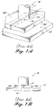
- FIGURES 1A and 1B One of the useful apparatus for FSW is shown in FIGURES 1A and 1B. As shown, two parts, exemplified by plates 10A', and 10B' are aligned so that edges of the plates to be welded together are held in direct contact on a backing plate 12'.
- An FSW tool W has a shoulder 14' at its distal end, and a non-consumable welding pin 16' extending downwards centrally from the shoulder.
- the rotating pin 16' As the rotating tool W' is brought into contact with the interface between plates 10B' and 10A', the rotating pin 16' is forced into contact with the material of both plates, as shown.
- the rotation of the pin in the material and rubbing of the shoulder against the upper surface of the material produces a large amount of frictional heating of both the welding tool and the plate interface. This heat softens the material of the plates in the vicinity of the rotating pin and shoulder, causing commingling of material, which upon hardening, forms a weld.
- the tool is moved longitudinally along the interface between plates 10A' and 10B', thereby forming an elongate weld all along the interface between the plates.
- the welding tool's shoulder 14' prevents softened material from the plates from escaping upwards, and forces the material into the weld joint. When the weld is completed, the welding tool is retracted.
- welds produced by the prior art friction stir welding process can produce smooth welds for certain materials, but for no-extrudable aluminum alloys, the maximum spindle speed is severely limited by adherence of the material to the welding tool shoulder and pin.
- these alloys exemplified by aluminum alloys 7075, 2014, 2090, and 2024, as the spindle speed increases, and correspondingly the heat input to the weld increases, the surface texture of the upper surface of the weld degrades by becoming rougher.
- the aluminum material adheres and builds up on the welding tool shoulder, tearing away material from the sides of the weld surface. For long welds, this condition can cause such excessive buildup that continuing the weld becomes impossible.
- the overheated welding tool can sometimes partially tear away surface material from the center of the weld surface, producing a "fish scale" appearance on the upper surface of the weld which progressively worsens along the length of the weld.
- a rough weld surface is undesirable, and requires additional machining to produce a smooth surface.
- Rough surfaces often provide points of initiation of fatigue cracks, and are therefore generally undesirable, especially if the welded part is to be used under conditions that could cause fatigue, such as cyclical conditions of applied load.
- FSW process that produces a weld of reduced surface roughness that would not require subsequent machining, for most applications, and that would have a uniform, smooth surface texture.
- the invention provides a method and apparatus for producing a friction stir weld of difficult to weld materials, such as non-extrudable aluminum alloys, that has a smoother surface than heretofore achieved with conventional friction stir welding equipment.
- the weld is produced at higher speeds and has a commercially acceptable surface smoothness so that it does not require subsequent machining for most purposes.
- the rate of welding limitation on non-extrudable materials is caused by excessive heat generated during the friction stir welding process at the surfaces of contact between the tool and the workpiece being welded. While a certain amount of heat is necessary to cause softening of the material to form the weld, excessive heat causes the softened material to adhere to the rotating pin and shoulder of the friction stir welding tool. The rotational and lateral movement of the tool against these adhesive-type forces causes the irregular weld surface. Therefore, the invention provides a method of friction stir welding that includes the step of simultaneously cooling the welding tool during the welding process to remove excess heat.
- This method allows a significant increase in welding rate, preferably at least about a 20% increase, and more preferably at least about a 100% increase, while maintaining an acceptable weld smoothness.
- the invention provides apparatus for friction stir welding that are cooled by a coolant.
- the coolant is circulated in the body of the tool to remove excess heat.
- the friction stir welding tool of the invention has a tool body with a rotatable, usually non-consumable, pin and shoulder at its distal end that are adapted for stir welding parts together.
- the tool body has an internal space that is in heat-conducting communication with the pin, and preferably also the shoulder, of the welding tool.
- the internal space is adapted for flowing a coolant therethrough to remove excess heat from the tool, including heat conducted from the shoulder and pin.
- heat is removed from the friction stir welding tool by a jacket that surrounds a distal portion of the tool body.
- the jacket has an inlet that is in fluid communication with a source of coolant, and an outlet for exit of heated coolant.
- the removal of heat is achieved by spraying a coolant (such as cold air, or a liquid coolant, such as water) onto the tool, and surrounding surfaces being welded, during the welding step.
- a coolant such as cold air, or a liquid coolant, such as water
- the tool portion being cooled is equipped with fins to facilitate heat removal.
- friction stir welds of even non-extrudable aluminum alloys are produced at commercially useful rates and have such a reduced surface roughness texture that they may be used commercially.
- a one-quarter inch thick extrudable aluminum alloy such as alloy 6061
- a friction stir welding tool rotating at 1600 rpm, at a rate of 15 inches per minute
- a non-extrudable alloy would have to be welded at a lower tool rotation rate and slower rate of welding.
- a one-eighth inch thick non-extrudable alloy such as alloy 2024
- a tool rotation speed of about 500 rpm for a weld rate of 3.5 inches per minute. This produces a weld throughout the workpiece, that has a surface of acceptable smoothness, without need for subsequent machining.
- the same one-eighth inch thick workpiece of 2024 alloy can be welded at a tool rotation speed of at least about 800 rpm to produce a weld at a rate of about eight inches per minute, that extends throughout the workpiece and that has a commercially acceptable smooth surface.
- a one-eighth inch thick workpiece of 7075 aluminum alloy (a non-extrudable alloy)
- 7075 aluminum alloy can be welded with a tool rotating at 1100 rpm, and a welding rate of 13 inches per minute to produce a weld that extends throughout the workpiece, with a surface of acceptable smoothness without subsequent machining.
- the same 7075 alloy workpiece would have been welded with a tool rotating at 600 rpm and producing a weld at a rate of only seven inches per minute.
- the invention allows a significant increase in the rate of rotation of the friction stir welding tool, with a concomitant dramatic increase in the rate of welding, in inches per minute.
- the invention allows an increase in welding rate of at least about 20%, most preferably at least about 100%, while maintaining a weld surface smoothness that is usually commercially acceptable, without requiring subsequent machining, although such machining may optionally be performed for specific applications.
- the invention provides a range of apparatus for removing excess heat, and the preferred embodiments of these apparatus are illustrated in the accompanying FIGURES, for ease of explanation.
- FIGURES for ease of explanation.
- other apparatus that perform the same function, of removing excess heat, so that a smoother weld surface is produced at a faster rate, are also within the scope of the invention.
- FIGURE 2 a schematic side view of a preferred embodiment of an apparatus in accordance with the invention, a substantially cylindrical weld tool body 30 having a proximal end 34, for operative connection to a drive motor for rotating the tool, and a distal end 36, that is equipped with a shoulder 38 and a substantially cylindrical pin 40 extending axially downward through a center of the shoulder.
- the pin 40 has a tip 42 and an outer surface that is helically grooved.
- the shoulder 38 is usually slightly peaked upward, from its circular periphery to the pin 40 at its center, at an angle of about 10°.
- a nozzle 50 extends in proximity to the welding tool body 30, in particular to the distal end 36, when a workpiece 20 is being welded on a backing plate 24.
- the rotating cylindrical pin has a tip 42 at its distal end that extends through the workpiece 20 to a depth to provide a minimal clearance between it and the backing plate 24.
- the pin extends substantially through the entire thickness of the workpiece 20, to produce a continuous weld 26 through the entire workpiece.
- the nozzle is in fluid communication with a source of coolant, such as a liquid or air, that is supplied under pressure to the nozzle, so that coolant exits the nozzle in a mist that impinges directly on the distal end 36 of the tool, and the surrounding workpiece 20.
- the coolant removes excess heat from both the exposed portion of the shoulder 38 that is above the workpiece 20 during welding, the workpiece 20 itself, and the weld 26 that is being formed. Heat travels by conduction from the hot rotating pin 40 and the shoulder 38 to their surroundings, namely, the workpiece 20 and the weld 26, from which the coolant then removes the heat. As a result, the temperatures of the surface of the rotating shoulder 38 and workpiece are significantly lower than would have been the case, but for the supply of coolant. These reduced surface temperatures caused by removal of excess heat, as explained above, provide a smoother weld surface at a faster weld rate.
- the amount of coolant should be controlled to avoid removal of so much heat as to interfere with the welding operation. A coolant rate of about 0.01 gpm is usually suitable and the rate may readily be optimized for a specific application.
- FIGURE 3 illustrates, schematically, in cross section, an internally cooled FSW tool in accordance with the invention.
- the substantially cylindrical tool body 60 has a proximal end 62 for coupling to a motor for rotating the tool, and a threaded distal end 64.
- a cap-shaped shoulder 66 with a circular shoulder base 65 and an internally threaded collar 67, is threadingly engaged to the distal end 64 of the FSW to produce an internal cylindrical space 74 between the base 63 of the tool body 60 and the base 65 of the shoulder.
- a pin preferably with a helically grooved exterior, extends downward from the center of the base of the shoulder.
- the tool includes an internal space, preferably a serpentine or tortuous internal space, that is in fluid communication with a source of coolant, and a sink for receiving heated coolant.
- the internal space is made up of vertical spaced and horizontal bores.
- a substantially horizontal inlet bore 70 penetrates to about the center of the distal end 64 of the cylindrical tool body 60.
- a central vertical bore 72 extends downward from the farthest extent of the horizontal bore 70 to exit from the base 63 of the distal end 64 of the tool body 60 so that it is in fluid communication with space 74.
- An annular space 76 concentric with the central bore 72, surrounds the central bore 72 and extends from the base 63 of the tool body 60 to below the inlet bore 70.
- the central bore 72 is in fluid communication with the annular space through internal space 74 at the very distal end 63 of the tool body 60.
- An exit bore 78 extends from an upper end of the annular space 76. Coolant fluid entering the inlet bore 70 flows down the central bore 72, into the internal cylindrical space 74, into the annular space 76 and out of the exit bore 78.
- a cylindrical coolant collar 80 In order to direct the coolant, a cylindrical coolant collar 80, concentric with and spaced from the tool body 60, surrounds the inlet 70 and outlet 78 bores.
- the collar 80 is sealed against the body 60 of the tool with an upper O-ring seal 82 above the inlet bore 70, and is also sealed against the tool body with a lower O-ring seal 84 below the exit bore 78.
- the collar 80 is sealed to the tool body 60 by a third O-ring 86 located between the inlet 70 and outlet 78 bores.
- the collar 80 forms a separate inlet compartment 90 that is in fluid communication with the inlet bore 70, and an outlet compartment 96 that is in fluid communication with the outlet bore 78.
- a coolant inlet hose 92 is coupled to the inlet compartment 90 of the collar, and a coolant outlet hose 98 is coupled to the outlet compartment 96 of the collar 80. Control of coolant flow is important to avoid overcooling of the tool thereby interfering with the welding process.
- a coolant rate of about 0.1 gallons per minute is suitable.
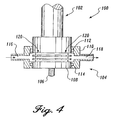
- FIGURE 4 An alternative embodiment, using an external cooling jacket, is illustrated schematically in FIGURE 4.
- the cylindrical welding tool body 100 has a proximal end 102 adapted for coupling to a means for rotating the tool, and a distal end 104 equipped with a central downwardly extending pin 106, surrounded by a shoulder 108.
- the substantially cylindrical distal end 104 of the tool body 100 is equipped with an external structure designed to dissipate heat, in this instance a series of circumferentially extending fins 120. The structure increases the surface area of the distal end, thereby permitting removal of larger amounts of heat for more effective cooling.
- a substantially cylindrical jacket 110 surrounds the finned distal end 104 of the tool 100, and is sealed against the tool body 100 by an upper O-ring 112, and a lower O-ring 114.
- the jacket 110 surrounds the fins 120, and is spaced from the fins to provide an annular region 122 that is in fluid communication with an inlet port 116 of the jacket, and an outlet port 118.
- coolant fluid enters the inlet port 116, flows into the annular space and around the fins 120, and exits from the outlet port 118, removing heat from the surface of the tool 100.
- the welding tool is cooled by using cold air as a coolant.
- the welding tool 100 is equipped with a series of circumferentially extending cooling fins 120 on its distal end 104.
- at least one nozzle 125 is oriented to continuously blast cold air, or another cold gas, onto the fins 120 of the welding tool to provide cooling.
- this removal of excess heat results in a cooler welding tool so that a weld with a uniform, smooth upper surface is produced, at a faster rate.
- a weld that is significantly smoother than achievable with prior art friction stir welding techniques and tools is produced.
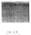
- FIGURE 6A an optical micrograph of an aluminum alloy 2024 stir weld at magnification of eight times, a weld produced according to the prior art is rough, having open tears on its upper surface. The weld was produced at a FSW tool rotation speed of 640 rpm, and a weld rate of 6.3 inches per minute.
- FIGURE 6B an optical micrograph at the same magnification for the same material, has a uniform, smooth surface, without surface tears.
- This weld was produced by a FSW tool rotating at 640 rpm and welding at a rate of 6.3 inches per minute.
- the weld surface shown in FIGURE 6B was produced with an air/water mist applied at the junction between the tool shoulder and the weld surface, on the side opposite the direction of welding. It may be expected that this reduction in roughness will reduce the likelihood of fatigue crack initiation and surface corrosion and would therefore prolong the life (and safety) of welded parts. Also, it is expected that long welds could be performed without material buildup on the shoulder.
- any means-plus-function clauses are intended to cover the structures described herein as performing the recited function, and not only structural equivalents, but also equivalent structures.
- a nail and a screw may not be structural equivalents in that a nail employs a cylindrical surface to secure wooden parts together, whereas a screw employs a helical surface, in the environment of fastening wooden parts, a nail and a screw may nevertheless be equivalent structures.
Landscapes
- Engineering & Computer Science (AREA)
- Mechanical Engineering (AREA)
- Physics & Mathematics (AREA)
- Thermal Sciences (AREA)
- Pressure Welding/Diffusion-Bonding (AREA)
Abstract
Description
- The invention relates to a method and apparatus for friction stir welding. More particularly, in accordance with the invention, excess heat produced in the friction stir welding process is removed so that a smoother weld surface is produced.
- Friction stir welding (FSW) is a relatively new welding process for joining together parts of materials such as metals, plastics, and other materials that will soften and commingle under applied frictional heat to become integrally connected. A detailed description of the FSW apparatus and process may be found in Patent Publications WO 93/10935; WO 95/26254; and U.S. Patent 5,460,317, all of which are hereby fully incorporated by reference. One of the useful apparatus for FSW is shown in FIGURES 1A and 1B. As shown, two parts, exemplified by
plates 10A', and 10B' are aligned so that edges of the plates to be welded together are held in direct contact on a backing plate 12'. An FSW tool W has a shoulder 14' at its distal end, and a non-consumable welding pin 16' extending downwards centrally from the shoulder. As the rotating tool W' is brought into contact with the interface betweenplates 10B' and 10A', the rotating pin 16' is forced into contact with the material of both plates, as shown. The rotation of the pin in the material and rubbing of the shoulder against the upper surface of the material produces a large amount of frictional heating of both the welding tool and the plate interface. This heat softens the material of the plates in the vicinity of the rotating pin and shoulder, causing commingling of material, which upon hardening, forms a weld. The tool is moved longitudinally along the interface betweenplates 10A' and 10B', thereby forming an elongate weld all along the interface between the plates. The welding tool's shoulder 14' prevents softened material from the plates from escaping upwards, and forces the material into the weld joint. When the weld is completed, the welding tool is retracted. - Welds produced by the prior art friction stir welding process can produce smooth welds for certain materials, but for no-extrudable aluminum alloys, the maximum spindle speed is severely limited by adherence of the material to the welding tool shoulder and pin. For these alloys, exemplified by aluminum alloys 7075, 2014, 2090, and 2024, as the spindle speed increases, and correspondingly the heat input to the weld increases, the surface texture of the upper surface of the weld degrades by becoming rougher. At higher spindle speeds, and higher heat input, the aluminum material adheres and builds up on the welding tool shoulder, tearing away material from the sides of the weld surface. For long welds, this condition can cause such excessive buildup that continuing the weld becomes impossible. Also, the overheated welding tool can sometimes partially tear away surface material from the center of the weld surface, producing a "fish scale" appearance on the upper surface of the weld which progressively worsens along the length of the weld. For certain applications such a rough weld surface is undesirable, and requires additional machining to produce a smooth surface. Rough surfaces often provide points of initiation of fatigue cracks, and are therefore generally undesirable, especially if the welded part is to be used under conditions that could cause fatigue, such as cyclical conditions of applied load. There exists a need for a FSW process that produces a weld of reduced surface roughness that would not require subsequent machining, for most applications, and that would have a uniform, smooth surface texture.
- The invention provides a method and apparatus for producing a friction stir weld of difficult to weld materials, such as non-extrudable aluminum alloys, that has a smoother surface than heretofore achieved with conventional friction stir welding equipment. The weld is produced at higher speeds and has a commercially acceptable surface smoothness so that it does not require subsequent machining for most purposes.
- In accordance with the invention, it has now been found that the rate of welding limitation on non-extrudable materials, imposed by the increasing roughness of the weld surface as welding rate increases, is caused by excessive heat generated during the friction stir welding process at the surfaces of contact between the tool and the workpiece being welded. While a certain amount of heat is necessary to cause softening of the material to form the weld, excessive heat causes the softened material to adhere to the rotating pin and shoulder of the friction stir welding tool. The rotational and lateral movement of the tool against these adhesive-type forces causes the irregular weld surface. Therefore, the invention provides a method of friction stir welding that includes the step of simultaneously cooling the welding tool during the welding process to remove excess heat. This method allows a significant increase in welding rate, preferably at least about a 20% increase, and more preferably at least about a 100% increase, while maintaining an acceptable weld smoothness. Moreover, the invention provides apparatus for friction stir welding that are cooled by a coolant.
- In one embodiment the coolant is circulated in the body of the tool to remove excess heat. In this embodiment, the friction stir welding tool of the invention has a tool body with a rotatable, usually non-consumable, pin and shoulder at its distal end that are adapted for stir welding parts together. The tool body has an internal space that is in heat-conducting communication with the pin, and preferably also the shoulder, of the welding tool. The internal space is adapted for flowing a coolant therethrough to remove excess heat from the tool, including heat conducted from the shoulder and pin.
- In another embodiment, heat is removed from the friction stir welding tool by a jacket that surrounds a distal portion of the tool body. The jacket has an inlet that is in fluid communication with a source of coolant, and an outlet for exit of heated coolant. Thus, when the tool is in use, coolant flows through the jacket removing heat from the tool, so that excess heat is removed from the rotatable pin and shoulder.
- In another embodiment, the removal of heat is achieved by spraying a coolant (such as cold air, or a liquid coolant, such as water) onto the tool, and surrounding surfaces being welded, during the welding step. Preferably, the tool portion being cooled is equipped with fins to facilitate heat removal.
- In accordance with the invention, friction stir welds of even non-extrudable aluminum alloys are produced at commercially useful rates and have such a reduced surface roughness texture that they may be used commercially.
- The foregoing aspects and many of the attendant advantages of this invention will become more readily appreciated as the same becomes better understood by reference to the following detailed description, when taken in conjunction with the accompanying drawings, wherein:
- FIGURE 1A is a schematic diagram of a prior art friction stir welding tool;
- FIGURE 1B is a schematic end view showing a prior art friction stir welding tool in use;
- FIGURE 2 illustrates a friction stir welding apparatus of the invention, including a nozzle for providing a coolant; and
- FIGURE 3 is a schematic diagram, in cross-section, of an embodiment of an internally cooled welding tool of the invention;
- FIGURE 4 is a schematic side view, in partial cross section, showing an externally jacketed embodiment of the tool of the invention;
- FIGURE 5 is a schematic side view of an air cooled, finned embodiment of a tool of the invention;
- FIGURE 6A is an optical micrograph showing details of the surface of a weld using a prior art friction stir welding tool; and
- FIGURE 6B is an optical micrograph of a surface of a weld made in accordance with the invention.
- In accordance with the invention, excess heat is removed from a friction stir welding tool (FSW) to reduce the degree of adherence between the tool and softened, difficult to weld material, such as non-extrudable aluminum alloys, so that a weld with a smoother surface is produced at a faster rate. Such smooth surface welds have many potential advantages, not only aesthetic, but also in reducing the risk of the initiation of fatigue cracking and corrosion. Moreover, the production of such welds eliminates, or reduces, the need for costly further machining of the weld to produce a smooth surface. The invention also increases welding rate by allowing higher FSW tool rotational speeds.
- In accordance with the method of the invention, excess heat is removed from the friction stir welding tool while the friction stir weld is being formed. Thus, the heat removal is simultaneous with the welding operation. While the method and apparatus of the invention are applicable to all kinds of material that are subject to friction stir welding, the invention is particularly useful when applied to materials that are difficult to friction stir weld, such as the non-extrudable aluminum alloys, exemplified by the 2024, 7075, 2014, and 2090 alloys. In the prior art, these alloys are typically welded at a much slower rate than the extrudable aluminum alloys, in order to produce a weld that extends throughout the workpiece, and that has a surface smoothness that is commercially acceptable, without need for subsequent machining. Thus, while a one-quarter inch thick extrudable aluminum alloy, such as alloy 6061, may be welded with a friction stir welding tool rotating at 1600 rpm, at a rate of 15 inches per minute, to produce a smooth weld; a non-extrudable alloy would have to be welded at a lower tool rotation rate and slower rate of welding. Typically, in the prior art, a one-eighth inch thick non-extrudable alloy, such as alloy 2024, may be welded at a tool rotation speed of about 500 rpm for a weld rate of 3.5 inches per minute. This produces a weld throughout the workpiece, that has a surface of acceptable smoothness, without need for subsequent machining. In accordance with the invention, the same one-eighth inch thick workpiece of 2024 alloy can be welded at a tool rotation speed of at least about 800 rpm to produce a weld at a rate of about eight inches per minute, that extends throughout the workpiece and that has a commercially acceptable smooth surface. Similarly, a one-eighth inch thick workpiece of 7075 aluminum alloy (a non-extrudable alloy), can be welded with a tool rotating at 1100 rpm, and a welding rate of 13 inches per minute to produce a weld that extends throughout the workpiece, with a surface of acceptable smoothness without subsequent machining. In the prior art, not using the tools and method of the invention, the same 7075 alloy workpiece would have been welded with a tool rotating at 600 rpm and producing a weld at a rate of only seven inches per minute.
- From the foregoing, it is clear that the invention allows a significant increase in the rate of rotation of the friction stir welding tool, with a concomitant dramatic increase in the rate of welding, in inches per minute. Preferably, the invention allows an increase in welding rate of at least about 20%, most preferably at least about 100%, while maintaining a weld surface smoothness that is usually commercially acceptable, without requiring subsequent machining, although such machining may optionally be performed for specific applications.
- The invention provides a range of apparatus for removing excess heat, and the preferred embodiments of these apparatus are illustrated in the accompanying FIGURES, for ease of explanation. Clearly, other apparatus that perform the same function, of removing excess heat, so that a smoother weld surface is produced at a faster rate, are also within the scope of the invention.
- Referring to FIGURE 2, a schematic side view of a preferred embodiment of an apparatus in accordance with the invention, a substantially cylindrical
weld tool body 30 having aproximal end 34, for operative connection to a drive motor for rotating the tool, and adistal end 36, that is equipped with ashoulder 38 and a substantiallycylindrical pin 40 extending axially downward through a center of the shoulder. As shown, thepin 40 has atip 42 and an outer surface that is helically grooved. Theshoulder 38 is usually slightly peaked upward, from its circular periphery to thepin 40 at its center, at an angle of about 10°. - In accordance with the invention, a
nozzle 50 extends in proximity to thewelding tool body 30, in particular to thedistal end 36, when aworkpiece 20 is being welded on abacking plate 24. The rotating cylindrical pin has atip 42 at its distal end that extends through theworkpiece 20 to a depth to provide a minimal clearance between it and thebacking plate 24. Thus, the pin extends substantially through the entire thickness of theworkpiece 20, to produce acontinuous weld 26 through the entire workpiece. The nozzle is in fluid communication with a source of coolant, such as a liquid or air, that is supplied under pressure to the nozzle, so that coolant exits the nozzle in a mist that impinges directly on thedistal end 36 of the tool, and the surroundingworkpiece 20. Thus, the coolant removes excess heat from both the exposed portion of theshoulder 38 that is above theworkpiece 20 during welding, theworkpiece 20 itself, and theweld 26 that is being formed. Heat travels by conduction from the hotrotating pin 40 and theshoulder 38 to their surroundings, namely, theworkpiece 20 and theweld 26, from which the coolant then removes the heat. As a result, the temperatures of the surface of therotating shoulder 38 and workpiece are significantly lower than would have been the case, but for the supply of coolant. These reduced surface temperatures caused by removal of excess heat, as explained above, provide a smoother weld surface at a faster weld rate. The amount of coolant should be controlled to avoid removal of so much heat as to interfere with the welding operation. A coolant rate of about 0.01 gpm is usually suitable and the rate may readily be optimized for a specific application. - FIGURE 3 illustrates, schematically, in cross section, an internally cooled FSW tool in accordance with the invention. As shown, the substantially
cylindrical tool body 60 has aproximal end 62 for coupling to a motor for rotating the tool, and a threadeddistal end 64. A cap-shapedshoulder 66, with acircular shoulder base 65 and an internally threadedcollar 67, is threadingly engaged to thedistal end 64 of the FSW to produce an internalcylindrical space 74 between the base 63 of thetool body 60 and thebase 65 of the shoulder. A pin, preferably with a helically grooved exterior, extends downward from the center of the base of the shoulder. The tool includes an internal space, preferably a serpentine or tortuous internal space, that is in fluid communication with a source of coolant, and a sink for receiving heated coolant. In the embodiment shown, the internal space is made up of vertical spaced and horizontal bores. Thus, a substantially horizontal inlet bore 70 penetrates to about the center of thedistal end 64 of thecylindrical tool body 60. A centralvertical bore 72 extends downward from the farthest extent of the horizontal bore 70 to exit from thebase 63 of thedistal end 64 of thetool body 60 so that it is in fluid communication withspace 74. Anannular space 76, concentric with thecentral bore 72, surrounds thecentral bore 72 and extends from thebase 63 of thetool body 60 to below the inlet bore 70. Thus, thecentral bore 72 is in fluid communication with the annular space throughinternal space 74 at the verydistal end 63 of thetool body 60. An exit bore 78 extends from an upper end of theannular space 76. Coolant fluid entering the inlet bore 70 flows down thecentral bore 72, into the internalcylindrical space 74, into theannular space 76 and out of the exit bore 78. - In order to direct the coolant, a
cylindrical coolant collar 80, concentric with and spaced from thetool body 60, surrounds theinlet 70 andoutlet 78 bores. Thecollar 80 is sealed against thebody 60 of the tool with an upper O-ring seal 82 above the inlet bore 70, and is also sealed against the tool body with a lower O-ring seal 84 below the exit bore 78. In addition, thecollar 80 is sealed to thetool body 60 by a third O-ring 86 located between theinlet 70 andoutlet 78 bores. Thus, thecollar 80 forms aseparate inlet compartment 90 that is in fluid communication with the inlet bore 70, and anoutlet compartment 96 that is in fluid communication with the outlet bore 78. Acoolant inlet hose 92 is coupled to theinlet compartment 90 of the collar, and acoolant outlet hose 98 is coupled to theoutlet compartment 96 of thecollar 80. Control of coolant flow is important to avoid overcooling of the tool thereby interfering with the welding process. A coolant rate of about 0.1 gallons per minute is suitable. - An alternative embodiment, using an external cooling jacket, is illustrated schematically in FIGURE 4. In this embodiment, the cylindrical
welding tool body 100 has aproximal end 102 adapted for coupling to a means for rotating the tool, and adistal end 104 equipped with a central downwardly extendingpin 106, surrounded by ashoulder 108. The substantially cylindricaldistal end 104 of thetool body 100 is equipped with an external structure designed to dissipate heat, in this instance a series of circumferentially extendingfins 120. The structure increases the surface area of the distal end, thereby permitting removal of larger amounts of heat for more effective cooling. A substantiallycylindrical jacket 110 surrounds the finneddistal end 104 of thetool 100, and is sealed against thetool body 100 by an upper O-ring 112, and a lower O-ring 114. Thus, thejacket 110 surrounds thefins 120, and is spaced from the fins to provide an annular region 122 that is in fluid communication with aninlet port 116 of the jacket, and anoutlet port 118. In use, coolant fluid enters theinlet port 116, flows into the annular space and around thefins 120, and exits from theoutlet port 118, removing heat from the surface of thetool 100. This removal of excess heat, that can be controlled by controlling the temperature of incoming coolant and its flow rate, allows the production of a weld of substantially uniform smoothness at a much faster rate, even when a high-strength aluminum alloy, such as aluminum 2024 or 7075, is being welded. As before, a coolant rate of about 0.1 gpm is usually suitable, and the rate may be readily optimized by experimentation for any specific application. - In a yet further embodiment, illustrated schematically in FIGURE 5, the welding tool is cooled by using cold air as a coolant. In this instance, as above, the
welding tool 100 is equipped with a series of circumferentially extending coolingfins 120 on itsdistal end 104. However, instead of a surroundingjacket 110, at least onenozzle 125 is oriented to continuously blast cold air, or another cold gas, onto thefins 120 of the welding tool to provide cooling. As above, this removal of excess heat results in a cooler welding tool so that a weld with a uniform, smooth upper surface is produced, at a faster rate. - In accordance with the invention, a weld that is significantly smoother than achievable with prior art friction stir welding techniques and tools is produced. As can be seen from FIGURE 6A, an optical micrograph of an aluminum alloy 2024 stir weld at magnification of eight times, a weld produced according to the prior art is rough, having open tears on its upper surface. The weld was produced at a FSW tool rotation speed of 640 rpm, and a weld rate of 6.3 inches per minute. Welds produced in accordance with the invention, exemplified by FIGURE 6B, an optical micrograph at the same magnification for the same material, has a uniform, smooth surface, without surface tears. This weld was produced by a FSW tool rotating at 640 rpm and welding at a rate of 6.3 inches per minute. The weld surface shown in FIGURE 6B was produced with an air/water mist applied at the junction between the tool shoulder and the weld surface, on the side opposite the direction of welding. It may be expected that this reduction in roughness will reduce the likelihood of fatigue crack initiation and surface corrosion and would therefore prolong the life (and safety) of welded parts. Also, it is expected that long welds could be performed without material buildup on the shoulder.
- Although only a few exemplary embodiments of this invention have been described in detail above, those skilled in the art will readily appreciate that many modifications are possible in the exemplary embodiments without materially departing from the novel teachings and advantages of this invention. Accordingly, all such modifications are intended to be included within the scope of this invention as defined in the following claims. In the claims, any means-plus-function clauses are intended to cover the structures described herein as performing the recited function, and not only structural equivalents, but also equivalent structures. Thus, although a nail and a screw may not be structural equivalents in that a nail employs a cylindrical surface to secure wooden parts together, whereas a screw employs a helical surface, in the environment of fastening wooden parts, a nail and a screw may nevertheless be equivalent structures.
Claims (13)
- A method of friction stir welding, the method comprising:(a) using a rotating friction stir welding tool to weld a workpiece comprised of a difficult to friction stir weld material;(b) simultaneously removing excess heat produced by the using of the friction stir welding tool;
whereby the removing of heat produces a smoother weld surface, without machining the weld surface, at a faster rate. - The method of Claim 1, wherein the removing of excess heat comprises cooling the rotating tool by flowing a coolant through internal spaces of the tool.
- The method of Claim 1 or 2, wherein the removal of excess heat comprises cooling the tool by spraying a mist of a coolant onto the tool during the step of welding.
- The method of Claim 1 or 2, wherein the removal of excess heat is by flowing coolant around exterior surfaces of the tool.
- The method of Claim 2, 3 or 4 wherein the coolant comprises air and/or water.
- The method of any of Claims 1-5, wherein the smoother weld surface is produced at a rate of welding that would produce a rough surfaced weld when welding without the step of simultaneously removing excess heat.
- In a friction stir welding tool, the tool comprising a tool body having a pin and shoulder at a distal end, the pin and shoulder adapted for generating frictional heat when rotating in contact with parts to be welded together, the heat causing a weld to form between the parts, the improvement comprising:an internal space defined within the body of the welding tool, the space in fluid communication with a source of coolant and walls of the space in heat conducting communication with the distal end of the tool body, whereby, when coolant flows through the space during welding operations, the distal end is cooled.
- The tool of Claim 7, wherein the internal space is in fluid communication with a collar surrounding the tool body, the collar partitioned into inlet and outlet sections, the inlet section of the collar in fluid communication with an inlet of the internal space, and the source of coolant.
- In a combination with a stir welding tool, the combination comprising:(a) a friction stir welding tool comprising a tool body having a pin and shoulder at a distal end, the pin and shoulder generating frictional heat when rotating in contact with parts to be welded together, the heat causing a weld to form between the parts; and(b) a coolant distribution device, in fluid communication with a source of coolant, the device aligned to direct coolant around the distal end of the tool body, when the tool is used to weld.
- The combination of Claim 13, wherein the coolant distribution device is a nozzle able to produce a mist of coolant therethrough or to produce a blast of cold air therethrough.
- In a friction stir welding tool, the tool comprising a tool body having a pin and shoulder at a distal end of the tool body, the pin and shoulder adapted for generating frictional heat when rotating in contact with a workpiece being welded, said heat causing a weld to form, the improvement comprising:a jacket surrounding the distal end of the tool body, the jacket having an inlet in fluid communication with a source of coolant, and an outlet for exit of heated coolant, whereby, when coolant flows through the jacket during welding, excess heat is removed from the distal end of the tool body.
- The method of any of Claims 1-6 or 11, wherein the welding is at a rate at least about 20% or 100% greater than achievable without simultaneous cooling to produce a weld surface of substantially the same roughness.
- The method of any of Claims 1-6 or 11 or 12, wherein the workpiece is comprised of a non-extrudable aluminum alloy selected from the group consisting of the 2014, 2024, 2090 and 7075 alloys.
Priority Applications (1)
| Application Number | Priority Date | Filing Date | Title |
|---|---|---|---|
| DE69724326.5T DE69724326T3 (en) | 1996-05-31 | 1997-05-16 | Oscillating friction stir welding with simultaneous cooling |
Applications Claiming Priority (2)
| Application Number | Priority Date | Filing Date | Title |
|---|---|---|---|
| US08/655,926 US6516992B1 (en) | 1996-05-31 | 1996-05-31 | Friction stir welding with simultaneous cooling |
| US655926 | 1996-05-31 |
Publications (4)
| Publication Number | Publication Date |
|---|---|
| EP0810056A2 true EP0810056A2 (en) | 1997-12-03 |
| EP0810056A3 EP0810056A3 (en) | 1998-12-02 |
| EP0810056B1 EP0810056B1 (en) | 2003-08-27 |
| EP0810056B2 EP0810056B2 (en) | 2014-05-21 |
Family
ID=24630960
Family Applications (1)
| Application Number | Title | Priority Date | Filing Date |
|---|---|---|---|
| EP97201482.3A Expired - Lifetime EP0810056B2 (en) | 1996-05-31 | 1997-05-16 | Friction stir welding with simultaneous cooling |
Country Status (7)
| Country | Link |
|---|---|
| US (1) | US6516992B1 (en) |
| EP (1) | EP0810056B2 (en) |
| JP (1) | JP3530342B2 (en) |
| KR (1) | KR100492837B1 (en) |
| CN (1) | CN1084654C (en) |
| CA (1) | CA2204570C (en) |
| DE (1) | DE69724326T3 (en) |
Cited By (33)
| Publication number | Priority date | Publication date | Assignee | Title |
|---|---|---|---|---|
| WO1999058288A1 (en) * | 1998-05-14 | 1999-11-18 | R.J. Tower Corporation | Friction stir welding tool |
| EP0972605A3 (en) * | 1998-07-17 | 2001-01-31 | The Boeing Company | Integral corrosion protection of friction stir welded joints |
| US6193137B1 (en) * | 1997-07-23 | 2001-02-27 | Hitachi, Ltd. | Constructive body and friction stir welding method |
| EP1151820A2 (en) * | 2000-05-03 | 2001-11-07 | The BOC Group plc | Improvements in thermal welding |
| WO2002007923A1 (en) * | 2000-07-20 | 2002-01-31 | Eads Deutschland Gmbh | Method and device for friction stir welding with simultaneous cooling |
| US6352193B1 (en) | 2000-08-01 | 2002-03-05 | General Electric Company | Apparatus for joining electrically conductive materials |
| US6360937B1 (en) * | 1999-04-27 | 2002-03-26 | Fokker Aerostructures B.V. | Friction stir welding |
| WO2003035320A1 (en) * | 2001-10-23 | 2003-05-01 | Svensk Kärnbränslehantering Ab | Method for friction stir welding |
| EP1334793A1 (en) * | 2001-12-26 | 2003-08-13 | The Boeing Company | High strength friction stir welding |
| US6648206B2 (en) | 2000-05-08 | 2003-11-18 | Tracey W. Nelson | Friction stir welding using a superabrasive tool |
| US6676004B1 (en) | 2001-02-13 | 2004-01-13 | Edison Welding Institute, Inc. | Tool for friction stir welding |
| WO2004026521A1 (en) * | 2002-09-17 | 2004-04-01 | The Boeing Company | Method and apparstus for radiation assisted friction stir welding |
| US6913186B2 (en) | 2003-09-11 | 2005-07-05 | The Boeing Company | Apparatus and method for friction stir welding with a variable speed pin |
| US6994242B2 (en) | 2003-12-09 | 2006-02-07 | The Boeing Company | Friction stir weld tool and method |
| US7225968B2 (en) | 2003-08-04 | 2007-06-05 | Sii Megadiamond, Inc. | Crack repair using friction stir welding on materials including metal matrix composites, ferrous alloys, non-ferrous alloys, and superalloys |
| US7270257B2 (en) | 2003-01-30 | 2007-09-18 | Sii Megadiamond, Inc. | Out-of-position friction stir welding of high melting temperature alloys |
| GB2452885A (en) * | 2004-04-30 | 2009-03-18 | Tokyu Car Corp | A method of friction stir welding aluminium 5083 |
| US7530486B2 (en) | 2003-05-05 | 2009-05-12 | Sii Megadiamond, Inc. | Applications of friction stir welding using a superabrasive tool |
| US7608296B2 (en) | 2001-06-12 | 2009-10-27 | Brigham Young University | Anvil for friction stir welding high temperature materials |
| US7651018B2 (en) | 2004-10-05 | 2010-01-26 | Sii Megadiamond | Expandable mandrel for use in friction stir welding |
| EP2153927A1 (en) * | 2008-08-13 | 2010-02-17 | Delphi Technologies, Inc. | Spindle-integrated cooling and collection device for stir friction welder |
| EP2338632A1 (en) * | 2009-12-22 | 2011-06-29 | Harms & Wende GmbH & Co. KG | Friction stir spot welding tool |
| US8056797B2 (en) | 2005-10-05 | 2011-11-15 | Megastir Technologies | Expandable mandrel for use in friction stir welding |
| RU2446926C1 (en) * | 2010-11-18 | 2012-04-10 | Открытое акционерное общество "Национальный институт авиационных технологий" (ОАО "НИАТ") | Tool for friction welding by mixing |
| US8186561B2 (en) | 2004-03-24 | 2012-05-29 | Megastir Technologies, LLC | Solid state processing of hand-held knife blades to improve blade performance |
| US8550326B2 (en) | 2005-10-05 | 2013-10-08 | Megastir Technologies Llc | Expandable mandrel for use in friction stir welding |
| RU2517653C1 (en) * | 2012-12-20 | 2014-05-27 | Михаил Михайлович Штрикман | Tool for friction welding by mixing |
| US8955734B2 (en) | 2004-05-21 | 2015-02-17 | Smith International, Inc. | Ball hole welding using the friction stir welding (FSW) process |
| EP2883645A1 (en) * | 2013-12-16 | 2015-06-17 | The Boeing Company | Apparatus for and method of friction stir welding |
| US9242308B2 (en) | 2009-11-02 | 2016-01-26 | Megastir Technologies Llc | Out of position friction stir welding of casing and small diameter tubing or pipe |
| RU2603341C1 (en) * | 2015-04-29 | 2016-11-27 | Михаил Михайлович Штрикман | Processing tool with cooling device |
| RU2686494C1 (en) * | 2018-10-12 | 2019-04-29 | Закрытое акционерное общество "Чебоксарское предприятие "Сеспель" | Method of friction welding with mixing of joints of aluminium alloys |
| RU2746930C1 (en) * | 2020-10-23 | 2021-04-22 | Закрытое Акционерное Общество "Чебоксарское Предприятие "Сеспель" (ЗАО "Чебоксарское Предприятие "Сеспель") | Device and tool for friction welding with mixing of mainly sheet workpieces made of titanium and its alloys |
Families Citing this family (76)
| Publication number | Priority date | Publication date | Assignee | Title |
|---|---|---|---|---|
| KR19990083213A (en) * | 1998-04-16 | 1999-11-25 | 구마모토 마사히로 | Vacuum chamber member and production process thereof |
| JP4809521B2 (en) * | 2000-09-19 | 2011-11-09 | マンヨーツール株式会社 | Tool holder and its cooling device |
| JP3818084B2 (en) * | 2000-12-22 | 2006-09-06 | 日立電線株式会社 | Cooling plate and manufacturing method thereof, and sputtering target and manufacturing method thereof |
| DE10139687C1 (en) * | 2001-08-11 | 2003-02-20 | Eads Deutschland Gmbh | Stirring tool for friction welding, has control which uses temperature values from the welding zone acquired by a sensor arranged with a measuring site in tool pin |
| JP4536992B2 (en) * | 2002-03-20 | 2010-09-01 | 川崎重工業株式会社 | Spot bonding method |
| US6908690B2 (en) * | 2002-04-29 | 2005-06-21 | The Boeing Company | Method and apparatus for friction stir welding |
| CA2494143C (en) * | 2002-08-07 | 2011-07-19 | Eclipse Aviation Corporation | Method of friction stir welding surfaces with polymer sealant |
| WO2004091839A2 (en) * | 2003-04-11 | 2004-10-28 | Edison Welding Institute | Method and apparatus for locally clamping components that are to be joined by friction stir welding |
| JP2005074451A (en) * | 2003-08-29 | 2005-03-24 | Toyota Motor Corp | Friction stir welding method and friction stir welding apparatus |
| US7121448B2 (en) * | 2003-08-29 | 2006-10-17 | General Electric Company | Friction stir welding apparatus and associated thermal management systems and methods |
| US7225967B2 (en) | 2003-12-16 | 2007-06-05 | The Boeing Company | Structural assemblies and preforms therefor formed by linear friction welding |
| US7398911B2 (en) * | 2003-12-16 | 2008-07-15 | The Boeing Company | Structural assemblies and preforms therefor formed by friction welding |
| JP4085988B2 (en) * | 2004-02-20 | 2008-05-14 | マツダ株式会社 | Rotating tool for friction welding equipment |
| US7275675B1 (en) | 2004-08-20 | 2007-10-02 | United States Of America As Represented By The Administrator Of The National Aeronautics And Space Administration | Friction stir weld tools |
| US7383975B2 (en) * | 2004-08-30 | 2008-06-10 | Alcoa Inc. | Fracture resistant friction stir welding tools |
| US7401723B2 (en) * | 2004-08-30 | 2008-07-22 | Alcoa Inc. | Advanced friction stir welding tools |
| US7198189B2 (en) * | 2004-09-28 | 2007-04-03 | Alcoa Inc. | Multi-shouldered fixed bobbin tools for simultaneous friction stir welding of multiple parallel walls between parts |
| DE102005029882A1 (en) * | 2005-06-27 | 2006-12-28 | Gkss-Forschungszentrum Geesthacht Gmbh | Friction stir welding apparatus includes first inner segment surrounding a pin and having first friction surface segment surrounding the first inner segment and rotationally driven independently of the first inner segment |
| US7497917B2 (en) * | 2005-08-31 | 2009-03-03 | Gm Global Technology Operations, Inc. | Friction heating for joining dissimilar materials |
| US7508682B2 (en) * | 2005-09-19 | 2009-03-24 | Hitachi, Ltd. | Housing for an electronic circuit |
| US8397974B2 (en) | 2005-09-26 | 2013-03-19 | Aeroprobe Corporation | Self-reacting friction stir welding tool with the ability to add filler material |
| US9511445B2 (en) | 2014-12-17 | 2016-12-06 | Aeroprobe Corporation | Solid state joining using additive friction stir processing |
| US9511446B2 (en) | 2014-12-17 | 2016-12-06 | Aeroprobe Corporation | In-situ interlocking of metals using additive friction stir processing |
| US8875976B2 (en) | 2005-09-26 | 2014-11-04 | Aeroprobe Corporation | System for continuous feeding of filler material for friction stir welding, processing and fabrication |
| US20080041921A1 (en) * | 2005-09-26 | 2008-02-21 | Kevin Creehan | Friction stir fabrication |
| US8632850B2 (en) | 2005-09-26 | 2014-01-21 | Schultz-Creehan Holdings, Inc. | Friction fabrication tools |
| US9266191B2 (en) | 2013-12-18 | 2016-02-23 | Aeroprobe Corporation | Fabrication of monolithic stiffening ribs on metallic sheets |
| JP4327788B2 (en) * | 2005-11-08 | 2009-09-09 | 本田技研工業株式会社 | Friction stir welding method |
| JP4768418B2 (en) * | 2005-11-28 | 2011-09-07 | 川崎重工業株式会社 | Friction stir welding method |
| JP2007237282A (en) * | 2006-03-10 | 2007-09-20 | Osaka Univ | Method of joining metallic material |
| JP4861038B2 (en) * | 2006-03-31 | 2012-01-25 | 東急車輛製造株式会社 | Adapter, adapter cooling method and friction stir welding method |
| GB0609669D0 (en) * | 2006-05-15 | 2006-06-28 | Welding Inst | Friction stir method |
| ITBO20060415A1 (en) * | 2006-05-26 | 2007-11-27 | Pei Protezioni Elaborazioni | ASPIRATING DEVICE FOR MACHINE TOOLS, WELDING, OPERATORS AND SIMILAR |
| US20080217377A1 (en) * | 2007-03-06 | 2008-09-11 | Alcoa Inc. | Fracture Resistant Friction Stir Welding Tool |
| CN100460131C (en) * | 2007-04-24 | 2009-02-11 | 中国航空工业第一集团公司北京航空制造工程研究所 | Thermal-settling agitation fricting welding method and apparatus by array flow-jet impact |
| TW200932421A (en) * | 2007-08-31 | 2009-08-01 | Air Turbine Tech Inc | Apparatus and method for machining |
| US7793816B2 (en) * | 2007-09-07 | 2010-09-14 | Alcoa Inc. | Friction stir welding apparatus |
| US7854362B2 (en) * | 2008-03-14 | 2010-12-21 | Alcoa Inc. | Advanced multi-shouldered fixed bobbin tools for simultaneous friction stir welding of multiple parallel walls between parts |
| FR2933016B1 (en) * | 2008-06-30 | 2010-12-24 | Alcan Rhenalu | PULSE MIXING FRICTION WELDING PROCESS |
| CN101660032B (en) * | 2009-09-07 | 2011-04-13 | 重庆大学 | Method for processing surface of melting welding head |
| DE102009046816A1 (en) * | 2009-11-18 | 2011-05-19 | Robert Bosch Gmbh | Process for welding preparation of two plastic components |
| US8123104B1 (en) | 2010-04-06 | 2012-02-28 | United Launch Alliance, Llc | Friction welding apparatus, system and method |
| US8141764B1 (en) | 2010-04-06 | 2012-03-27 | United Launch Alliance, Llc | Friction stir welding apparatus, system and method |
| US7866532B1 (en) | 2010-04-06 | 2011-01-11 | United Launch Alliance, Llc | Friction stir welding apparatus, system and method |
| JP2013542076A (en) * | 2010-09-23 | 2013-11-21 | テクナラ エフエスダブリュ カンパニー, エルエルシー | How to hold a high speed friction spot welding tool |
| US9051633B2 (en) | 2010-10-08 | 2015-06-09 | Sumitomo Light Metal Industries, Ltd. | Aluminum alloy welded member |
| CN103167927B (en) | 2010-11-04 | 2015-10-14 | 株式会社Ihi | Friction-stir engagement device |
| CN102528268B (en) * | 2010-12-17 | 2014-05-07 | 中国科学院金属研究所 | Friction stir welding process for enhancing mechanical property of joint |
| JP5461476B2 (en) | 2011-05-27 | 2014-04-02 | 三菱重工業株式会社 | Friction stir welding equipment |
| CN103157893A (en) * | 2011-12-16 | 2013-06-19 | 宝山钢铁股份有限公司 | Welding method and welding device with weld joint water-cooled synchronously and from right side |
| CN102615419B (en) * | 2012-04-06 | 2014-04-16 | 江苏科技大学 | Dry cooling device and cooling method for friction stir welding seam |
| CN103639588B (en) * | 2013-11-11 | 2015-10-07 | 江苏科技大学 | A kind of solid state heat sink device for friction stir welding and welding method thereof |
| WO2015106455A1 (en) * | 2014-01-20 | 2015-07-23 | GM Global Technology Operations LLC | Welding method and system |
| CN104070287B (en) * | 2014-04-30 | 2016-05-18 | 燕山大学 | A kind of softening method of high strength alumin ium alloy friction stir welding and device of suppressing |
| CN104014926B (en) * | 2014-05-30 | 2016-08-17 | 北京赛福斯特技术有限公司 | Aclinal is from upset agitating friction welding method and instrument |
| DE102014010058B4 (en) * | 2014-07-07 | 2016-01-28 | Grenzebach Maschinenbau Gmbh | Method and device for fast and safe tool change in the process of friction stir welding and a computer program for performing the method |
| PT3069812T (en) * | 2015-03-18 | 2017-12-21 | Helmholtz-Zentrum Geesthacht Zentrum für Material-und Küstenforschung GmbH | Apparatus for friction stir welding with a shoulder comprising first and second through holes |
| US10086396B2 (en) * | 2016-03-28 | 2018-10-02 | Nazila Sedaei | Electro-anti deposit device for removing mineral deposits in drip irrigation systems |
| JP6143915B1 (en) * | 2016-04-28 | 2017-06-07 | 株式会社日立パワーソリューションズ | Friction stir welding equipment |
| CN106181017A (en) * | 2016-07-11 | 2016-12-07 | 中国船舶重工集团公司第七二五研究所 | A kind of friction stir welding method of corronil |
| US10279423B2 (en) * | 2016-08-17 | 2019-05-07 | The Boeing Company | Apparatuses and methods for fabricating metal matrix composite structures |
| US20180050419A1 (en) * | 2016-08-22 | 2018-02-22 | Novelis Inc. | Components and systems for friction stir welding and related processes |
| CN106735856A (en) * | 2017-02-23 | 2017-05-31 | 江苏科技大学 | A kind of agitating friction head water cooling plant and method |
| US11549157B2 (en) * | 2017-07-19 | 2023-01-10 | Shiv Nadar University | Method for modifying surface grain structure of the material and apparatus thereof |
| US11130192B2 (en) * | 2017-08-30 | 2021-09-28 | Mazak Corporation | Instrumented tool handler for friction stir welding |
| JP7089034B2 (en) | 2017-10-31 | 2022-06-21 | メルド マニファクチャリング コーポレーション | Solid-state laminated modeling system as well as material composition and structural background |
| CN108655668B (en) * | 2018-04-28 | 2020-06-19 | 武汉理工大学 | Forming and processing technology of aluminum alloy tailor-welded blank |
| CN108772667A (en) * | 2018-06-20 | 2018-11-09 | 辽宁忠旺集团有限公司 | A kind of friction stir welding method of track vehicle body aluminium alloy sheet |
| CN108788447A (en) * | 2018-08-09 | 2018-11-13 | 湖南文理学院 | A kind of orbit movable agitating friction welding equipment |
| CN111438434B (en) * | 2020-05-15 | 2021-07-09 | 沈阳飞机工业(集团)有限公司 | Cold-hot stretching-based friction stir sheet glue welding method |
| KR102231384B1 (en) * | 2020-09-02 | 2021-03-24 | 주식회사 태강기업 | Friction welding machine |
| FR3122110B1 (en) * | 2021-04-22 | 2023-07-21 | Inst Maupertuis | Electrospindle equipped with a cooling circuit |
| US11660700B2 (en) * | 2021-06-04 | 2023-05-30 | Dus Operating Inc. | Welding and deburring system with cryogenic cooling |
| CN113319599B (en) * | 2021-07-09 | 2023-01-17 | 重庆市超群工业股份有限公司 | Automobile hub machining system |
| CN113967783B (en) * | 2021-10-22 | 2022-08-02 | 南京工业大学 | Coaxial spray cooling coupling auxiliary FSW device and using method |
| WO2024034268A1 (en) * | 2022-08-08 | 2024-02-15 | 国立大学法人大阪大学 | Friction stir welding method and friction stir welding tool |
Citations (8)
| Publication number | Priority date | Publication date | Assignee | Title |
|---|---|---|---|---|
| GB591201A (en) † | 1944-05-02 | 1947-08-11 | Mallory Metallurg Prod Ltd | Improvements in or relating to welding electrode cooling |
| US3234643A (en) † | 1962-05-24 | 1966-02-15 | American Mach & Foundry | Friction welding |
| US3717539A (en) † | 1968-05-27 | 1973-02-20 | E Systems Inc | Ultrasonic welding apparatus |
| US4106167A (en) † | 1970-10-23 | 1978-08-15 | Penelope Jane Vesey Luc | Frictional method and machine for seaming tubular sections |
| WO1993010935A1 (en) * | 1991-12-06 | 1993-06-10 | The Welding Institute | Improvements relating to friction welding |
| US5248868A (en) † | 1992-05-22 | 1993-09-28 | Cusick Iii Joseph B | Melding gun |
| WO1995026254A1 (en) * | 1994-03-28 | 1995-10-05 | The Welding Institute | Friction stir welding |
| GB2306366A (en) * | 1995-10-20 | 1997-05-07 | Welding Inst | Friction stir welding |
Family Cites Families (4)
| Publication number | Priority date | Publication date | Assignee | Title |
|---|---|---|---|---|
| US3212182A (en) * | 1962-05-24 | 1965-10-19 | American Mach & Foundry | Friction welding |
| JPS51110455A (en) | 1975-03-25 | 1976-09-30 | Maruma Tractor & Equip | Junkatsuzaifunyugatatoratsukurinkuno nikumoryosetsuhoho oyobi sonoreikyakuhogosochi |
| FR2659038B1 (en) * | 1990-03-02 | 1994-11-10 | Snecma | FRICTION WELDING PROCESS AND IMPLEMENTATION MACHINE. |
| US5138766A (en) * | 1990-04-26 | 1992-08-18 | Fuji Photo Equipment Co., Ltd. | Roller for transporting sheet-like material and method for manufacturing the same |
-
1996
- 1996-05-31 US US08/655,926 patent/US6516992B1/en not_active Expired - Lifetime
-
1997
- 1997-05-06 CA CA002204570A patent/CA2204570C/en not_active Expired - Lifetime
- 1997-05-16 EP EP97201482.3A patent/EP0810056B2/en not_active Expired - Lifetime
- 1997-05-16 DE DE69724326.5T patent/DE69724326T3/en not_active Expired - Lifetime
- 1997-05-26 JP JP13495497A patent/JP3530342B2/en not_active Expired - Lifetime
- 1997-05-28 CN CN97113488A patent/CN1084654C/en not_active Expired - Lifetime
- 1997-05-30 KR KR1019970022167A patent/KR100492837B1/en active IP Right Grant
Patent Citations (8)
| Publication number | Priority date | Publication date | Assignee | Title |
|---|---|---|---|---|
| GB591201A (en) † | 1944-05-02 | 1947-08-11 | Mallory Metallurg Prod Ltd | Improvements in or relating to welding electrode cooling |
| US3234643A (en) † | 1962-05-24 | 1966-02-15 | American Mach & Foundry | Friction welding |
| US3717539A (en) † | 1968-05-27 | 1973-02-20 | E Systems Inc | Ultrasonic welding apparatus |
| US4106167A (en) † | 1970-10-23 | 1978-08-15 | Penelope Jane Vesey Luc | Frictional method and machine for seaming tubular sections |
| WO1993010935A1 (en) * | 1991-12-06 | 1993-06-10 | The Welding Institute | Improvements relating to friction welding |
| US5248868A (en) † | 1992-05-22 | 1993-09-28 | Cusick Iii Joseph B | Melding gun |
| WO1995026254A1 (en) * | 1994-03-28 | 1995-10-05 | The Welding Institute | Friction stir welding |
| GB2306366A (en) * | 1995-10-20 | 1997-05-07 | Welding Inst | Friction stir welding |
Non-Patent Citations (2)
| Title |
|---|
| DAWES C J ET AL: "FRICTION STIR PROCESS WELDS ALUMINUM ALLOYS" 1 March 1996 , WELDING JOURNAL INCLUDING: WELDING RESEARCH, VOL. 75, NR. 3, PAGE(S) 41 - 45 XP000587301 * the whole document * * |
| Dawes C J et al: Friction Stir Process welds Aluminum Alloys (01.03.1996) † |
Cited By (53)
| Publication number | Priority date | Publication date | Assignee | Title |
|---|---|---|---|---|
| US6533493B2 (en) | 1997-07-23 | 2003-03-18 | Hitachi, Ltd. | Structural body |
| US6193137B1 (en) * | 1997-07-23 | 2001-02-27 | Hitachi, Ltd. | Constructive body and friction stir welding method |
| US6527470B2 (en) | 1997-07-23 | 2003-03-04 | Hitachi, Ltd. | Structural body and friction stir welding method |
| US6530713B2 (en) | 1997-07-23 | 2003-03-11 | Hitachi, Ltd. | Structural body |
| WO1999058288A1 (en) * | 1998-05-14 | 1999-11-18 | R.J. Tower Corporation | Friction stir welding tool |
| EP0972605A3 (en) * | 1998-07-17 | 2001-01-31 | The Boeing Company | Integral corrosion protection of friction stir welded joints |
| US6360937B1 (en) * | 1999-04-27 | 2002-03-26 | Fokker Aerostructures B.V. | Friction stir welding |
| EP1151820A2 (en) * | 2000-05-03 | 2001-11-07 | The BOC Group plc | Improvements in thermal welding |
| EP1151820A3 (en) * | 2000-05-03 | 2003-07-02 | The BOC Group plc | Improvements in thermal welding |
| US8302834B2 (en) | 2000-05-08 | 2012-11-06 | MegaStar Technologies LLC | Friction stir welding using a superabrasive tool |
| US6779704B2 (en) | 2000-05-08 | 2004-08-24 | Tracy W. Nelson | Friction stir welding of metal matrix composites, ferrous alloys, non-ferrous alloys, and superalloys using a superabrasive tool |
| US7661572B2 (en) | 2000-05-08 | 2010-02-16 | Brigham Young University | Friction stir welding using a superabrasive tool |
| US7993575B2 (en) | 2000-05-08 | 2011-08-09 | Megastir Technologies, LLC | Friction stir welding using a superabrasive tool |
| US6648206B2 (en) | 2000-05-08 | 2003-11-18 | Tracey W. Nelson | Friction stir welding using a superabrasive tool |
| US7152776B2 (en) | 2000-05-08 | 2006-12-26 | Sii Megadiamond, Inc. | Friction stir welding using a superabrasive tool |
| US7124929B2 (en) | 2000-05-08 | 2006-10-24 | Sii Megadiamond, Inc. | Friction stir welding of metal matrix composites, ferrous alloys, non-ferrous alloys, and superalloys using a superabrasive tool |
| US9061370B2 (en) | 2000-05-08 | 2015-06-23 | Brigham Young University | Friction stir welding using a superabrasive tool |
| WO2002007923A1 (en) * | 2000-07-20 | 2002-01-31 | Eads Deutschland Gmbh | Method and device for friction stir welding with simultaneous cooling |
| US6772935B2 (en) | 2000-07-20 | 2004-08-10 | Eads Deutschland Gmbh | Method and device for friction stir welding with simultaneous cooling |
| US6352193B1 (en) | 2000-08-01 | 2002-03-05 | General Electric Company | Apparatus for joining electrically conductive materials |
| US6676004B1 (en) | 2001-02-13 | 2004-01-13 | Edison Welding Institute, Inc. | Tool for friction stir welding |
| US7608296B2 (en) | 2001-06-12 | 2009-10-27 | Brigham Young University | Anvil for friction stir welding high temperature materials |
| WO2003035320A1 (en) * | 2001-10-23 | 2003-05-01 | Svensk Kärnbränslehantering Ab | Method for friction stir welding |
| EP1334793A1 (en) * | 2001-12-26 | 2003-08-13 | The Boeing Company | High strength friction stir welding |
| US6780525B2 (en) | 2001-12-26 | 2004-08-24 | The Boeing Company | High strength friction stir welding |
| EP1813377A3 (en) * | 2001-12-26 | 2009-08-26 | The Boeing Company | High strength friction stir welding |
| CN1301822C (en) * | 2002-09-17 | 2007-02-28 | 波音公司 | Radiation assisted friction welding |
| WO2004026521A1 (en) * | 2002-09-17 | 2004-04-01 | The Boeing Company | Method and apparstus for radiation assisted friction stir welding |
| US6776328B2 (en) | 2002-09-17 | 2004-08-17 | The Boeing Company | Radiation assisted friction welding |
| US7270257B2 (en) | 2003-01-30 | 2007-09-18 | Sii Megadiamond, Inc. | Out-of-position friction stir welding of high melting temperature alloys |
| US7530486B2 (en) | 2003-05-05 | 2009-05-12 | Sii Megadiamond, Inc. | Applications of friction stir welding using a superabrasive tool |
| US7225968B2 (en) | 2003-08-04 | 2007-06-05 | Sii Megadiamond, Inc. | Crack repair using friction stir welding on materials including metal matrix composites, ferrous alloys, non-ferrous alloys, and superalloys |
| US6913186B2 (en) | 2003-09-11 | 2005-07-05 | The Boeing Company | Apparatus and method for friction stir welding with a variable speed pin |
| US6994242B2 (en) | 2003-12-09 | 2006-02-07 | The Boeing Company | Friction stir weld tool and method |
| US8186561B2 (en) | 2004-03-24 | 2012-05-29 | Megastir Technologies, LLC | Solid state processing of hand-held knife blades to improve blade performance |
| GB2452885B (en) * | 2004-04-30 | 2009-04-22 | Tokyu Car Corp | Method of connecting metal material |
| GB2452885A (en) * | 2004-04-30 | 2009-03-18 | Tokyu Car Corp | A method of friction stir welding aluminium 5083 |
| US8955734B2 (en) | 2004-05-21 | 2015-02-17 | Smith International, Inc. | Ball hole welding using the friction stir welding (FSW) process |
| US7651018B2 (en) | 2004-10-05 | 2010-01-26 | Sii Megadiamond | Expandable mandrel for use in friction stir welding |
| US8550326B2 (en) | 2005-10-05 | 2013-10-08 | Megastir Technologies Llc | Expandable mandrel for use in friction stir welding |
| US8056797B2 (en) | 2005-10-05 | 2011-11-15 | Megastir Technologies | Expandable mandrel for use in friction stir welding |
| EP2153927A1 (en) * | 2008-08-13 | 2010-02-17 | Delphi Technologies, Inc. | Spindle-integrated cooling and collection device for stir friction welder |
| US9242308B2 (en) | 2009-11-02 | 2016-01-26 | Megastir Technologies Llc | Out of position friction stir welding of casing and small diameter tubing or pipe |
| WO2011080157A1 (en) * | 2009-12-22 | 2011-07-07 | Harms & Wende Gmbh & Co. Kg | Friction spot welding tool |
| EP2338632A1 (en) * | 2009-12-22 | 2011-06-29 | Harms & Wende GmbH & Co. KG | Friction stir spot welding tool |
| RU2446926C1 (en) * | 2010-11-18 | 2012-04-10 | Открытое акционерное общество "Национальный институт авиационных технологий" (ОАО "НИАТ") | Tool for friction welding by mixing |
| RU2517653C1 (en) * | 2012-12-20 | 2014-05-27 | Михаил Михайлович Штрикман | Tool for friction welding by mixing |
| EP2883645A1 (en) * | 2013-12-16 | 2015-06-17 | The Boeing Company | Apparatus for and method of friction stir welding |
| US9289849B2 (en) | 2013-12-16 | 2016-03-22 | The Boeing Company | Apparatus for friction stir welding |
| EP3031565A1 (en) * | 2013-12-16 | 2016-06-15 | The Boeing Company | Apparatus for and method of friction stir welding |
| RU2603341C1 (en) * | 2015-04-29 | 2016-11-27 | Михаил Михайлович Штрикман | Processing tool with cooling device |
| RU2686494C1 (en) * | 2018-10-12 | 2019-04-29 | Закрытое акционерное общество "Чебоксарское предприятие "Сеспель" | Method of friction welding with mixing of joints of aluminium alloys |
| RU2746930C1 (en) * | 2020-10-23 | 2021-04-22 | Закрытое Акционерное Общество "Чебоксарское Предприятие "Сеспель" (ЗАО "Чебоксарское Предприятие "Сеспель") | Device and tool for friction welding with mixing of mainly sheet workpieces made of titanium and its alloys |
Also Published As
| Publication number | Publication date |
|---|---|
| CA2204570C (en) | 2005-07-12 |
| EP0810056B2 (en) | 2014-05-21 |
| KR970073845A (en) | 1997-12-10 |
| KR100492837B1 (en) | 2005-09-02 |
| CA2204570A1 (en) | 1997-11-30 |
| JP3530342B2 (en) | 2004-05-24 |
| US6516992B1 (en) | 2003-02-11 |
| DE69724326T3 (en) | 2014-08-14 |
| EP0810056A3 (en) | 1998-12-02 |
| DE69724326D1 (en) | 2003-10-02 |
| CN1167663A (en) | 1997-12-17 |
| DE69724326T2 (en) | 2004-02-19 |
| EP0810056B1 (en) | 2003-08-27 |
| JPH1052770A (en) | 1998-02-24 |
| CN1084654C (en) | 2002-05-15 |
Similar Documents
| Publication | Publication Date | Title |
|---|---|---|
| US6516992B1 (en) | Friction stir welding with simultaneous cooling | |
| KR100492835B1 (en) | Friction Stir Welding Tool and Method | |
| CA2182719C (en) | Friction stir welding | |
| US7832613B2 (en) | Friction stir welding system | |
| EP1077787B1 (en) | Friction stir welding tool | |
| EP1029627B1 (en) | Friction agitation jointing method of metal workpieces | |
| TWI538758B (en) | Welding repairing technology and friction stir welding method using the same | |
| CN110524105B (en) | Rotary welding tool for friction welding and welding method | |
| CN211305187U (en) | Rotary welding tool for friction welding | |
| CN111098016A (en) | Friction stir welding equipment and cooling protection device thereof | |
| JP2000225476A (en) | Friction-stir-welding method for works made of metal | |
| CN220591876U (en) | Self-heating friction stir tool | |
| KR100668705B1 (en) | Apparatus for friction stir spot welding | |
| JPH11291067A (en) | Friction joining method | |
| CN110129792B (en) | Method and device for preparing composite pipe/coating by full-liquid stirring and semi-solid stirring coating method | |
| EP1494832A1 (en) | Apparatus and method for forming a weld joint having improved physical properties | |
| RU2243870C1 (en) | Method of spiral beading of pipes | |
| Abd El-Nasser et al. | Effect of the friction stir welding parameters on the mechanical properties of Al 5083 joint | |
| Gerçekcioglu et al. | BALKANTRIB’O5 5 th INTERNATIONAL CONFERENCE ON TRIBOLOGY JUNE. 15-18. 2005 | |
| JPS63169201A (en) | Cutting and removing method for joint burr on steel pipe at high temperature |
Legal Events
| Date | Code | Title | Description |
|---|---|---|---|
| PUAI | Public reference made under article 153(3) epc to a published international application that has entered the european phase |
Free format text: ORIGINAL CODE: 0009012 |
|
| AK | Designated contracting states |
Kind code of ref document: A2 Designated state(s): DE FR GB SE |
|
| PUAL | Search report despatched |
Free format text: ORIGINAL CODE: 0009013 |
|
| AK | Designated contracting states |
Kind code of ref document: A3 Designated state(s): DE FR GB SE |
|
| 17P | Request for examination filed |
Effective date: 19990507 |
|
| 17Q | First examination report despatched |
Effective date: 20020225 |
|
| GRAH | Despatch of communication of intention to grant a patent |
Free format text: ORIGINAL CODE: EPIDOS IGRA |
|
| GRAH | Despatch of communication of intention to grant a patent |
Free format text: ORIGINAL CODE: EPIDOS IGRA |
|
| GRAA | (expected) grant |
Free format text: ORIGINAL CODE: 0009210 |
|
| REG | Reference to a national code |
Ref country code: SE Ref legal event code: TRGR |
|
| AK | Designated contracting states |
Designated state(s): DE FR GB SE |
|
| REG | Reference to a national code |
Ref country code: GB Ref legal event code: FG4D |
|
| REF | Corresponds to: |
Ref document number: 69724326 Country of ref document: DE Date of ref document: 20031002 Kind code of ref document: P |
|
| ET | Fr: translation filed | ||
| PLBQ | Unpublished change to opponent data |
Free format text: ORIGINAL CODE: EPIDOS OPPO |
|
| PLBI | Opposition filed |
Free format text: ORIGINAL CODE: 0009260 |
|
| PLAX | Notice of opposition and request to file observation + time limit sent |
Free format text: ORIGINAL CODE: EPIDOSNOBS2 |
|
| 26 | Opposition filed |
Opponent name: AIRBUS SAS Effective date: 20040527 |
|
| PLAX | Notice of opposition and request to file observation + time limit sent |
Free format text: ORIGINAL CODE: EPIDOSNOBS2 |
|
| PLBB | Reply of patent proprietor to notice(s) of opposition received |
Free format text: ORIGINAL CODE: EPIDOSNOBS3 |
|
| APBP | Date of receipt of notice of appeal recorded |
Free format text: ORIGINAL CODE: EPIDOSNNOA2O |
|
| APAH | Appeal reference modified |
Free format text: ORIGINAL CODE: EPIDOSCREFNO |
|
| APBP | Date of receipt of notice of appeal recorded |
Free format text: ORIGINAL CODE: EPIDOSNNOA2O |
|
| APBQ | Date of receipt of statement of grounds of appeal recorded |
Free format text: ORIGINAL CODE: EPIDOSNNOA3O |
|
| APBQ | Date of receipt of statement of grounds of appeal recorded |
Free format text: ORIGINAL CODE: EPIDOSNNOA3O |
|
| APBU | Appeal procedure closed |
Free format text: ORIGINAL CODE: EPIDOSNNOA9O |
|
| PLAY | Examination report in opposition despatched + time limit |
Free format text: ORIGINAL CODE: EPIDOSNORE2 |
|
| PLBC | Reply to examination report in opposition received |
Free format text: ORIGINAL CODE: EPIDOSNORE3 |
|
| APBM | Appeal reference recorded |
Free format text: ORIGINAL CODE: EPIDOSNREFNO |
|
| APBP | Date of receipt of notice of appeal recorded |
Free format text: ORIGINAL CODE: EPIDOSNNOA2O |
|
| APAH | Appeal reference modified |
Free format text: ORIGINAL CODE: EPIDOSCREFNO |
|
| APBQ | Date of receipt of statement of grounds of appeal recorded |
Free format text: ORIGINAL CODE: EPIDOSNNOA3O |
|
| APBU | Appeal procedure closed |
Free format text: ORIGINAL CODE: EPIDOSNNOA9O |
|
| PUAH | Patent maintained in amended form |
Free format text: ORIGINAL CODE: 0009272 |
|
| STAA | Information on the status of an ep patent application or granted ep patent |
Free format text: STATUS: PATENT MAINTAINED AS AMENDED |
|
| 27A | Patent maintained in amended form |
Effective date: 20140521 |
|
| AK | Designated contracting states |
Kind code of ref document: B2 Designated state(s): DE FR GB SE |
|
| REG | Reference to a national code |
Ref country code: DE Ref legal event code: R102 Ref document number: 69724326 Country of ref document: DE |
|
| REG | Reference to a national code |
Ref country code: DE Ref legal event code: R102 Ref document number: 69724326 Country of ref document: DE Effective date: 20140521 |
|
| REG | Reference to a national code |
Ref country code: SE Ref legal event code: RPEO |
|
| REG | Reference to a national code |
Ref country code: FR Ref legal event code: PLFP Year of fee payment: 20 |
|
| PGFP | Annual fee paid to national office [announced via postgrant information from national office to epo] |
Ref country code: GB Payment date: 20160527 Year of fee payment: 20 Ref country code: DE Payment date: 20160527 Year of fee payment: 20 |
|
| PGFP | Annual fee paid to national office [announced via postgrant information from national office to epo] |
Ref country code: SE Payment date: 20160527 Year of fee payment: 20 Ref country code: FR Payment date: 20160530 Year of fee payment: 20 |
|
| REG | Reference to a national code |
Ref country code: DE Ref legal event code: R071 Ref document number: 69724326 Country of ref document: DE |
|
| REG | Reference to a national code |
Ref country code: GB Ref legal event code: PE20 Expiry date: 20170515 |
|
| REG | Reference to a national code |
Ref country code: SE Ref legal event code: EUG |
|
| PG25 | Lapsed in a contracting state [announced via postgrant information from national office to epo] |
Ref country code: GB Free format text: LAPSE BECAUSE OF EXPIRATION OF PROTECTION Effective date: 20170515 |