EP0809852B1 - Isolation haute tension permeable aux gaz - Google Patents
Isolation haute tension permeable aux gaz Download PDFInfo
- Publication number
- EP0809852B1 EP0809852B1 EP96904049A EP96904049A EP0809852B1 EP 0809852 B1 EP0809852 B1 EP 0809852B1 EP 96904049 A EP96904049 A EP 96904049A EP 96904049 A EP96904049 A EP 96904049A EP 0809852 B1 EP0809852 B1 EP 0809852B1
- Authority
- EP
- European Patent Office
- Prior art keywords
- high voltage
- voltage insulation
- insulation according
- sheath
- filter
- Prior art date
- Legal status (The legal status is an assumption and is not a legal conclusion. Google has not performed a legal analysis and makes no representation as to the accuracy of the status listed.)
- Expired - Lifetime
Links
- 238000009413 insulation Methods 0.000 title claims abstract description 44
- 239000002826 coolant Substances 0.000 claims abstract description 8
- 239000012212 insulator Substances 0.000 claims description 18
- 239000004744 fabric Substances 0.000 claims description 10
- 239000011324 bead Substances 0.000 claims description 9
- 239000011521 glass Substances 0.000 claims description 9
- 239000006260 foam Substances 0.000 claims description 8
- 239000000843 powder Substances 0.000 claims description 7
- 230000005684 electric field Effects 0.000 claims description 4
- 238000005192 partition Methods 0.000 claims 4
- 239000004020 conductor Substances 0.000 description 17
- 239000001307 helium Substances 0.000 description 12
- 229910052734 helium Inorganic materials 0.000 description 12
- SWQJXJOGLNCZEY-UHFFFAOYSA-N helium atom Chemical compound [He] SWQJXJOGLNCZEY-UHFFFAOYSA-N 0.000 description 12
- 239000007789 gas Substances 0.000 description 11
- 238000002955 isolation Methods 0.000 description 10
- 238000012360 testing method Methods 0.000 description 9
- 229920001903 high density polyethylene Polymers 0.000 description 5
- 239000004700 high-density polyethylene Substances 0.000 description 5
- 230000015556 catabolic process Effects 0.000 description 4
- 238000001816 cooling Methods 0.000 description 4
- 239000002887 superconductor Substances 0.000 description 4
- 238000004804 winding Methods 0.000 description 4
- 239000011152 fibreglass Substances 0.000 description 3
- 239000004593 Epoxy Substances 0.000 description 2
- 239000004809 Teflon Substances 0.000 description 2
- 229920006362 Teflon® Polymers 0.000 description 2
- 239000003822 epoxy resin Substances 0.000 description 2
- 239000003292 glue Substances 0.000 description 2
- 238000009434 installation Methods 0.000 description 2
- 239000002184 metal Substances 0.000 description 2
- 229920000647 polyepoxide Polymers 0.000 description 2
- 239000011148 porous material Substances 0.000 description 2
- 239000007787 solid Substances 0.000 description 2
- 229910000831 Steel Inorganic materials 0.000 description 1
- 239000000853 adhesive Substances 0.000 description 1
- 238000004026 adhesive bonding Methods 0.000 description 1
- 230000001070 adhesive effect Effects 0.000 description 1
- 238000005352 clarification Methods 0.000 description 1
- 238000000576 coating method Methods 0.000 description 1
- 238000001514 detection method Methods 0.000 description 1
- 238000010292 electrical insulation Methods 0.000 description 1
- 230000005611 electricity Effects 0.000 description 1
- 239000003365 glass fiber Substances 0.000 description 1
- 238000004519 manufacturing process Methods 0.000 description 1
- 239000000463 material Substances 0.000 description 1
- 238000000034 method Methods 0.000 description 1
- 239000000615 nonconductor Substances 0.000 description 1
- 239000004033 plastic Substances 0.000 description 1
- 229920003023 plastic Polymers 0.000 description 1
- 238000005086 pumping Methods 0.000 description 1
- 239000003566 sealing material Substances 0.000 description 1
- 229910000679 solder Inorganic materials 0.000 description 1
- 125000006850 spacer group Chemical group 0.000 description 1
- 239000010959 steel Substances 0.000 description 1
- 238000004046 wet winding Methods 0.000 description 1
Images


Classifications
-
- H—ELECTRICITY
- H01—ELECTRIC ELEMENTS
- H01F—MAGNETS; INDUCTANCES; TRANSFORMERS; SELECTION OF MATERIALS FOR THEIR MAGNETIC PROPERTIES
- H01F6/00—Superconducting magnets; Superconducting coils
- H01F6/06—Coils, e.g. winding, insulating, terminating or casing arrangements therefor
- H01F6/065—Feed-through bushings, terminals and joints
-
- H—ELECTRICITY
- H02—GENERATION; CONVERSION OR DISTRIBUTION OF ELECTRIC POWER
- H02G—INSTALLATION OF ELECTRIC CABLES OR LINES, OR OF COMBINED OPTICAL AND ELECTRIC CABLES OR LINES
- H02G15/00—Cable fittings
- H02G15/34—Cable fittings for cryogenic cables
-
- Y—GENERAL TAGGING OF NEW TECHNOLOGICAL DEVELOPMENTS; GENERAL TAGGING OF CROSS-SECTIONAL TECHNOLOGIES SPANNING OVER SEVERAL SECTIONS OF THE IPC; TECHNICAL SUBJECTS COVERED BY FORMER USPC CROSS-REFERENCE ART COLLECTIONS [XRACs] AND DIGESTS
- Y02—TECHNOLOGIES OR APPLICATIONS FOR MITIGATION OR ADAPTATION AGAINST CLIMATE CHANGE
- Y02E—REDUCTION OF GREENHOUSE GAS [GHG] EMISSIONS, RELATED TO ENERGY GENERATION, TRANSMISSION OR DISTRIBUTION
- Y02E40/00—Technologies for an efficient electrical power generation, transmission or distribution
- Y02E40/60—Superconducting electric elements or equipment; Power systems integrating superconducting elements or equipment
Definitions
- the invention relates to high voltage insulation according to the Preamble of claim 1.
- high vacuum also known to be an excellent electrical insulator, so that the high voltage strength of both the coils the connections are not a problem in normal operation.
- gas e.g. helium
- the breakdown voltage of Helium in the Paschen minimum is only about 160 V.
- the Isolation of the entire coil system including all connections and feed lines must therefore be designed for the Paschen minimum, i.e. the insulation must be "Paschen-tight".
- the cable connections between two coils or coil parts are mostly solder joints, which are, for example, in one metallic housing 1 (also called connection pot) are (see Fig. 1).
- the two wire ends of the to be connected Windings i.e. the cable sleeves 2, which are the actual ones Superconductor cables 3 are included with the connection housing tightly welded.
- the housing the cooling helium is also fed into and out of the cables.
- helium also flows through it tightly the housing welded tube 4 into the housing and from there half each in the interior of the two superconducting cables 3.
- Das Coolant can also flow through the conductor, for example Tube directly welded to the conductor sleeve become.
- Both the conductor ends and the He tube are from the electrical insulation 5 coated. If any Instrumentation such as pressure sensors or Voltage taps are provided, the corresponding Supply lines inside the helium supply or through own pipes corresponding to the He pipe are guided.
- the coil connection insulation before or after the first Cooling or final leak test depends depending on what isolation you use and what risk one is ready to enter. For example, you could Isolation only after cooling and the cold leak tests assemble. But that would be expensive, since the cryostat does this reopened and sufficient access to the coil connection points manufactured (including thermal insulation should be removed. If the isolation before the first Cold driving is applied, it should in the event of a occurring cold leak of the connector housing either itself be helium-tight or if the insulation is gas-permeable is for a possible repair of the housing just be removable. Adequate helium tightness, which must be guaranteed over many temperature cycles difficult to reach. In addition, the isolation in the case withstand a full He pressure. On the other hand easy disassembly would be desirable in any case, because then later leaks or damage in the Inside the connection housing (e.g. for the cable connection or the instrumentation) could be repaired more easily.
- the object of the present invention is accordingly based on specifying high-voltage insulation, which under cramped space is easy to assemble and remove is and takes up little space.
- the invention avoids the disadvantages of known high-voltage insulation of conductor connections and connections superconducting coils for voltages from a few kV.
- According to the invention becomes the connector housing of such Surround the connector loosely with an insulating sleeve into which a gas permeable and electrically insulating insert for Evacuation of the shell is used.
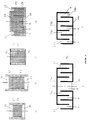
- Fig. 1 shows an embodiment of the invention in which the Insulation is designed to be screwed:
- the metallic Housing 1 and the bare ends of the conductor sheaths 2 and the He tube 4 are made of an insulator sleeve from parts 6 and 7.
- part 6 of the case is the insert 8 inserted (advantageously glued).
- the latter could be anywhere on the envelope both in part 6 and in part 7.
- Parts 6 and 7 are advantageously screwed together, so that part 6 can be easily assembled or removed can.
- the thread between the two shell parts is like this poems that at this point even at the highest possible Tension in the Paschen minimum no breakdown can occur.
- the assembly of the insulation according to Fig. 1 could for example so that even before the assembly of the housing 1 Part 7 is pushed over the conductor and pipe ends.
- the He connection, any instrumentation and the connection housing the parts 6 and 7 would then be screwed temporarily, put in the right position, and part 7 with the Insulations 5 of the conductor or pipe ends glued.
- the part 6 with the insert 8 would after the adhesive has hardened finally screwed to part 7.
- the insulation according to the invention fulfills all three mentioned Conditions.
- the space between the connector housing and the shell is sufficient over the insert 8 well evacuated.
- the opening has the additional advantage that there is a leak detector for an integral (warm) Leak test of the connection housing can be connected.
- the parts are 6 and 7, as shown in detail "variant A" of FIG. 1, releasably connected to one another via a flange connection.
- the seal between the flanges can be geometrically different shaped, but must again be “Paschen-dense” his.
- connection point between the shell parts 6 and 7 glue For higher voltages it may be necessary to use the Connection point between the shell parts 6 and 7 glue.
- the "variant B" in Fig. 1 is an example an easily detachable glue point Parts 6 and 7 put together and the connection point for example with "wet" epoxy resin-soaked insulator fabric wrapped so that a ring 9 arises. Instead of making a wet wrap, you could also stick on a solid ring. For a possible later dismantling only the ring 9 would have to be ground off. Both parts of the case could be used again.
- the insert 8 in the insulating sleeve has the task of Electricity transport in ionized gas at the "Paschen minimum” to avoid low gas pressures or to reduce them very strongly.
- a conventional filter e.g. an HDPE (high density polyethylene) filter is used become.
- a filter system consisting of several parts, used.
- 2a and b show such filter systems, which consist of filters 10 and 11, which are in an insulator tube 12 are glued.
- the rollover distance on the inner wall of the tube 12 extended by grooves.
- the grooves hinder (because of the changing angles of the field lines to the wall) continuous discharges.
- the filter system only made of foam, powder or glass beads 14, that of an insulator tube 15 and gas permeable fabrics or seven 16 are included.
- a pot-shaped insulator part (19) and a ring vessel Insulator (20) so that the discharge one after the other through the outer annulus (C) inner annulus (D) and the inner opening of the annular vessel (E) - or vice versa - must be done.
- the discharge current flows against the external one Tension.
- the outer annulus (C) and the inner opening of the ring vessel (E) are with a filter, sieve or fabric (17 or 18) completed.
- the whole of the three Partial spaces (C, D, E) existing discharge space between the Filters (or sieves or fabrics) can be used at lower ones Voltages be empty or is used to isolate higher voltages with glass beads, powder or open-cell foam filled.
- the isolator part (19) is either only from annular filter (17) or additional, the discharge space non-interrupting holding elements in its Location held.
- the filter systems shown in cross section ce. 2a to 2e need not be a round, of course, but can have any floor plan.
- the Figures 2d and 2e also as sections through cuboid Arrangements can be seen in which the parts 19 and 20 or 19a and 20a and then in two rectangular parts decaying filter 17 and also rectangular filter 18 via two side walls are glued so that the unloading space 21 or 21a is closed laterally.
- FIG. 2f Another embodiment of such a cuboid
- the arrangement is shown in Fig. 2f.
- the comb-shaped parts 19b and 20b and the rectangular filters 17b and 18b are over Side walls glued so that a meandering discharge space 21b arises.
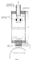
- FIG. 3 Another embodiment of the invention is shown in FIG. 3 shown.
- the housing has 22 conductors and / or pipe connections on two sides; it is from the Insulator cover consisting of parts 23, 24 and 25 surrounded.
- the filter 8 is inserted in the part 24, it could but again at any point in the envelope are located.
- the diameter of the part 24 is larger than that of part 25.
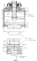
- FIG. 4 Another embodiment of the invention is shown in FIG. 4 shown.
- the electrical contact between the connector housing 26 and the potential shield 29 is produced via spring elements 30 These springs 30 are fixed to the potential screen 29 connected and form a pressure-loaded with the housing 26 Sliding contact.
- the assembly of this insulation corresponds to that of the insulation according to FIG. 1.
- parts 29 and 30 corresponding potential shield also in an arrangement like to use in Fig. 3. This would have to be in an up and down extended tube 23 a correspondingly long potential shield, that both the upper and lower thread and the Filters shielded, are used.
- the high-voltage insulation for devices according to the invention in gases at low pressures could be at the planned time Stellarator W7-X for "Paschen-tight" insulation of the Coil connections are used. There will be about 500 such isolations for test voltages between 10 and 20 kV needed. The test and demonstration cryostat for W7-X will contain about 50 conductor connection pots.
- the invention was tested in an embodiment according to FIG. 5.
- the gas atmosphere consisted of helium with various pressures in the range from 10 -4 mbar to 0.4 bar, so that the insulation was certainly exposed to the conditions of the Paschen minimum.
- the insulating sleeve was glued together from GRP parts or screwed, the two threads were with Teflon tapes sealed.
- the filter system consisted of a combination of two glued-in HDPE filters with pore sizes of approx. 250 ⁇ m and glass beads in between with diameters from 200 ⁇ m to 300 ⁇ m. The whole arrangement was concentric in a cylindrical, earthed vacuum vessel Metal arranged with an inner diameter of 315 mm.
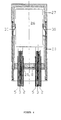
- Fig. 6 shows an experimental setup for testing a Device according to the invention with a further filter arrangement.
- the sectional views in Fig. 6 are for Clarification of the size relationships with dimensions (millimeters) Mistake.
- the dimensions in Figure 5 and Figure 6 represent specific embodiments only by way of example and can be specific to the dimensions of a realized structure can be adjusted.
- the arrangement according to Fig. 6 was in the same test facility at one temperature of approx. 80 K and in a helium atmosphere with pressures as above successfully tested up to 16 kV.
- the filter arrangement corresponds 2d. It was filled with glass beads and it was uses the same HDPE filter material.
- the filter arrangement can, as shown in Fig. 6 below, with inner spacers e.g.
- the insulating sleeve was made according to FIG. 1, Variant A, sealed with a flat Teflon ring (flange seal at the upper end). It could be shown that the Filter arrangement sufficient for the purposes described is gas permeable and the pumping of the device High vacuum allowed without significant delay.
Landscapes
- Engineering & Computer Science (AREA)
- Power Engineering (AREA)
- Filtering Of Dispersed Particles In Gases (AREA)
- Insulators (AREA)
Abstract
Claims (18)
- Isolation à haute tension pour l'isolation de connexions de câbles et/ou de bornes de courant et/ou de raccords de fluide réfrigérant de bobines d'aimant isolées sous vide, en particulier de bobines d'aimant supraconductrices comportant des câbles (2,3) refroidis intérieurement, caractérisée en ce que la zone à isoler est entourée d'une enveloppe isolante (6,7; 23,24,25), la paroi de l'enveloppe présente une ouverture et dans cette ouverture est engagé un insert perméable au gaz et isolant électriquement (8,10-21) pour l'évacuation de l'espace interne de l'enveloppe.
- Isolation à haute tension suivant la revendication 1, caractérisée en ce que l'insert (8, 10-21) est un filtre (8) ou un système de filtres (10-13; 14-16; 17-21).
- Isolation à haute tension suivant la revendication 1 ou 2, caractérisée en ce que la connexion entre les câbles ou la connexion électrique de la bobine d'aimant se trouve dans un boítier (1) et/ou l'alimentation ou l'évacuation de fluide réfrigérant s'effectue par l'intermédiaire d'un tel boítier (1) et les gaines (2) des câbles et/ou les conduits de fluide réfrigérant (4) sont soudés au boítier (1).
- Isolation à haute tension suivant une ou plusieurs des revendications précédentes, caractérisée en ce qu'elle comprend une première partie de paroi d'enveloppe (7) de forme plane et une seconde partie d'enveloppe (6) en forme de pot.
- Isolation à haute tension suivant une ou plusieurs des revendications 1 à 3, caractérisée en ce qu'elle comprend deux parties de paroi d'enveloppe (24,25) de forme plane et une partie d'enveloppe (23) de forme tubulaire.
- Isolation à haute tension suivant la revendication 4 ou 5, caractérisée en ce que les parties de paroi d'enveloppe (7; 24,25) présentent un nombre de passages pour les connexions électriques et les raccords du fluide réfrigérant.
- Isolation à haute tension suivant l'une au moins des deux revendications 4 et 6, caractérisée en ce que la partie de paroi d'enveloppe (7) et la partie d'enveloppe (6) peuvent être vissées l'une par rapport à l'autre.
- Isolation à haute tension suivant l'une au moins des deux revendications 5 et 6, caractérisée en ce que l'une ou les deux parties de paroi d'enveloppe (24,25) et la partie d'enveloppe (23) peuvent être vissées l'une par rapport à l'autre.
- Isolation à haute tension suivant l'une au moins des deux revendications 4 et 6, caractérisée en ce que la partie de paroi d'enveloppe (7) et la partie d'enveloppe (6) sont liées l'une à l'autre, d'une manière amovible, par l'intermédiaire d'une liaison par bride.
- Isolation à haute tension suivant l'une au moins des deux revendications 5 et 6, caractérisée en ce que l'une ou les deux parties de paroi d'enveloppe (24,25) et la partie d'enveloppe (23) sont liées l'une à l'autre, d'une manière amovible, par l'intermédiaire de liaisons du type à bride.
- Isolation à haute tension suivant l'une au moins des deux revendications 4 et 6, caractérisée en ce que la partie de paroi d'enveloppe (7) et la partie de paroi (6) sont collées l'une à l'autre.
- Isolation à haute tension suivant l'une au moins des deux revendications 5 et 6, caractérisée en ce que l'une ou les deux parties de paroi d'enveloppe (24,25) et la partie d'enveloppe (23) sont collées les unes aux autres.
- Isolation à haute tension suivant une ou plusieurs des revendications 2 à 12, caractérisée en ce que le système de filtres (10-13) comporte deux filtres (10) et (11) qui sont enfermés, à distance l'un de l'autre, dans un tube isolant (12) et dont l'espace intermédiaire est rempli d'une matière isolante (13) telle qu'une mousse, une poudre ou des perles de verre perméables aux gaz.
- Isolation à haute tension suivant une ou plusieurs des revendications 2 à 12, caractérisée en ce que le système de filtres (14-16) comporte des tissus ou des tamis perméables aux gaz qui sont enfermés, à distance l'un de l'autre, dans un tube isolant (15) et dont l'espace intermédiaire est rempli d'une matière isolante (14) telle qu'une mousse, une poudre ou des perles de verre perméables aux gaz.
- Isolation à haute tension suivant une ou plusieurs des revendications 2 à 12, caractérisée en ce que le système de filtres (17-21) comporte deux éléments isolants (19, 19a, 19b, 20, 20a, 20b) qui présentent la forme d'un récipient ouvert d'un côté avec des parois de fond, latérale et de séparation, et qui sont imbriqués l'un dans l'autre par leurs côtés ouverts, le trajet de décharge de la tension est constitué de chambres de décharge (C, D, E) reliées en série d'une façon sinueuse, une chambre externe (C) est obturée au moyen d'un filtre, d'un tamis ou d'un tissu (17) et une chambre interne (E) de l'élément isolant (20, 20a) ou une chambre externe de l'élément isolant (19b) est obturée au moyen d'un filtre, d'un tamis ou d'un tissu (18) et l'espace intermédiaire entre les filtres ou les tamis ou les tissus (17,18) est laissé vide ou est rempli d'une matière isolante (21) telle qu'une mousse, une poudre ou des perles de verre perméables aux gaz.
- Isolation à haute tension suivant la revendication 15, caractérisée en ce que les parois de fond des éléments isolants (19, 19a, 20, 20a) présentent une forme essentiellement circulaire, le premier élément isolant est réalisé sous la forme d'un pot (19) ou sous la forme d'un pot (19a) pourvu d'une paroi de séparation annulaire et le second élément isolant est réalisé sous la forme d'un récipient annulaire (20) ou d'un récipient annulaire (20a) pourvu d'une paroi de séparation annulaire de telle façon que soient formées des chambres de décharge annulaires (C,D) et une chambre de décharge (E) de forme tubulaire.
- Isolation à haute tension suivant la revendication 15, caractérisée en ce que les parois de fond des éléments isolants (19b, 20b) présentent une forme sensiblement rectangulaire et les parois latérales et de séparation sont disposées sensiblement perpendiculairement les unes aux autres.
- Isolation à haute tension suivant une ou plusieurs des revendications précédentes, caractérisée en ce que les points faibles de l'isolation sont protégés par l'intermédiaire d'un écran de potentiel (29) de telle façon qu'ils soient amenés à se trouver dans des zones à faibles intensités du champ électrique.
Applications Claiming Priority (3)
| Application Number | Priority Date | Filing Date | Title |
|---|---|---|---|
| DE19504857 | 1995-02-14 | ||
| DE19504857A DE19504857C2 (de) | 1995-02-14 | 1995-02-14 | Gasdurchlässige Hochspannungsisolation |
| PCT/EP1996/000559 WO1996025751A1 (fr) | 1995-02-14 | 1996-02-09 | Isolation haute tension permeable aux gaz |
Publications (2)
| Publication Number | Publication Date |
|---|---|
| EP0809852A1 EP0809852A1 (fr) | 1997-12-03 |
| EP0809852B1 true EP0809852B1 (fr) | 2000-01-19 |
Family
ID=7753905
Family Applications (1)
| Application Number | Title | Priority Date | Filing Date |
|---|---|---|---|
| EP96904049A Expired - Lifetime EP0809852B1 (fr) | 1995-02-14 | 1996-02-09 | Isolation haute tension permeable aux gaz |
Country Status (3)
| Country | Link |
|---|---|
| EP (1) | EP0809852B1 (fr) |
| DE (2) | DE19504857C2 (fr) |
| WO (1) | WO1996025751A1 (fr) |
Families Citing this family (1)
| Publication number | Priority date | Publication date | Assignee | Title |
|---|---|---|---|---|
| CN114171254B (zh) * | 2021-12-10 | 2024-12-17 | 国网上海市电力公司 | 一种适用于高温超导城市电力电缆的集成接头拓扑 |
Family Cites Families (3)
| Publication number | Priority date | Publication date | Assignee | Title |
|---|---|---|---|---|
| JPS60200579A (ja) * | 1984-03-26 | 1985-10-11 | Mitsubishi Electric Corp | 超電導装置 |
| EP0464498A3 (en) * | 1990-06-22 | 1992-03-04 | Kabushiki Kaisha Toshiba | Current lead |
| US5623240A (en) * | 1992-10-20 | 1997-04-22 | Sumitomo Heavy Industries, Ltd. | Compact superconducting magnet system free from liquid helium |
-
1995
- 1995-02-14 DE DE19504857A patent/DE19504857C2/de not_active Expired - Fee Related
-
1996
- 1996-02-09 WO PCT/EP1996/000559 patent/WO1996025751A1/fr not_active Ceased
- 1996-02-09 EP EP96904049A patent/EP0809852B1/fr not_active Expired - Lifetime
- 1996-02-09 DE DE59604231T patent/DE59604231D1/de not_active Expired - Fee Related
Also Published As
| Publication number | Publication date |
|---|---|
| WO1996025751A1 (fr) | 1996-08-22 |
| DE19504857A1 (de) | 1996-08-22 |
| DE19504857C2 (de) | 2002-02-07 |
| EP0809852A1 (fr) | 1997-12-03 |
| DE59604231D1 (de) | 2000-02-24 |
Similar Documents
| Publication | Publication Date | Title |
|---|---|---|
| DE2348895C2 (de) | Verbindung für Starkstromkabel | |
| DE69410579T2 (de) | Gasisolierte Hochspannungsleitung für lange Abstände | |
| DE2021066A1 (de) | Gekapselte gasisolierte Hochspannungsleitung | |
| CH664040A5 (de) | Druckgasisolierter stromwandler. | |
| EP0215286A1 (fr) | Transformateur à haute puissance pour une impulsion courte de haute tension et/ou de courant élevé | |
| DE4319682A1 (de) | Isolator mit internem Verbindungskanal | |
| EP0809852B1 (fr) | Isolation haute tension permeable aux gaz | |
| DE1807996A1 (de) | Einleiterwandler | |
| DE2233217A1 (de) | Trommelbare kabellaenge eines gasisolierten hochspannungskabels | |
| EP0653767B1 (fr) | Transformateur électrique à moyenne tension | |
| DE3542054C2 (de) | Endverschluß für insbesondere kunststoffisolierte Hochspannungskabel | |
| EP3631821A1 (fr) | Traversée à haute tension enfichable et appareil électrique comprenant la traversée à haute tension enfichable | |
| EP1844482B1 (fr) | Transformateur toroidal | |
| DE2327629A1 (de) | Durchfuehrungsisolator fuer hochspannungseinrichtungen und verfahren zu seiner herstellung | |
| DE69402862T2 (de) | Verfahren zur herstellung von im wesentlichen hohlzylinderförmigen giesslingen und im wesentlichen hohlzylinderförmiger giessling | |
| DE3512657C2 (fr) | ||
| DE2624325A1 (de) | Hochspannungsdurchfuehrung | |
| DE3644553C2 (fr) | ||
| DE1515513B1 (de) | Verbindungsmuffe für mit Strömungsmittel imprägnierte Metallmantel-Starkstromkabel | |
| DE202004007187U1 (de) | Prüfendverschluß für ein supraleitendes Kabel | |
| DE702787C (de) | Leistungstransformator | |
| DE3312025C2 (fr) | ||
| DE2604650B2 (de) | Geschirmtes Mittelspannungskabel mit Endmuffe | |
| DE3843907A1 (de) | Thermische isolierung | |
| EP1196711B1 (fr) | Isolateur axial convenant a la cryotechnique |
Legal Events
| Date | Code | Title | Description |
|---|---|---|---|
| PUAI | Public reference made under article 153(3) epc to a published international application that has entered the european phase |
Free format text: ORIGINAL CODE: 0009012 |
|
| 17P | Request for examination filed |
Effective date: 19970716 |
|
| AK | Designated contracting states |
Kind code of ref document: A1 Designated state(s): DE FR GB IT |
|
| GRAG | Despatch of communication of intention to grant |
Free format text: ORIGINAL CODE: EPIDOS AGRA |
|
| 17Q | First examination report despatched |
Effective date: 19990427 |
|
| GRAG | Despatch of communication of intention to grant |
Free format text: ORIGINAL CODE: EPIDOS AGRA |
|
| GRAH | Despatch of communication of intention to grant a patent |
Free format text: ORIGINAL CODE: EPIDOS IGRA |
|
| GRAH | Despatch of communication of intention to grant a patent |
Free format text: ORIGINAL CODE: EPIDOS IGRA |
|
| GRAA | (expected) grant |
Free format text: ORIGINAL CODE: 0009210 |
|
| AK | Designated contracting states |
Kind code of ref document: B1 Designated state(s): DE FR GB IT |
|
| REF | Corresponds to: |
Ref document number: 59604231 Country of ref document: DE Date of ref document: 20000224 |
|
| ITF | It: translation for a ep patent filed | ||
| ET | Fr: translation filed | ||
| GBT | Gb: translation of ep patent filed (gb section 77(6)(a)/1977) |
Effective date: 20000410 |
|
| PLBE | No opposition filed within time limit |
Free format text: ORIGINAL CODE: 0009261 |
|
| STAA | Information on the status of an ep patent application or granted ep patent |
Free format text: STATUS: NO OPPOSITION FILED WITHIN TIME LIMIT |
|
| 26N | No opposition filed | ||
| PGFP | Annual fee paid to national office [announced via postgrant information from national office to epo] |
Ref country code: GB Payment date: 20010207 Year of fee payment: 6 |
|
| PGFP | Annual fee paid to national office [announced via postgrant information from national office to epo] |
Ref country code: FR Payment date: 20010227 Year of fee payment: 6 |
|
| PGFP | Annual fee paid to national office [announced via postgrant information from national office to epo] |
Ref country code: DE Payment date: 20010411 Year of fee payment: 6 |
|
| REG | Reference to a national code |
Ref country code: GB Ref legal event code: IF02 |
|
| PG25 | Lapsed in a contracting state [announced via postgrant information from national office to epo] |
Ref country code: GB Free format text: LAPSE BECAUSE OF NON-PAYMENT OF DUE FEES Effective date: 20020209 |
|
| PG25 | Lapsed in a contracting state [announced via postgrant information from national office to epo] |
Ref country code: DE Free format text: LAPSE BECAUSE OF NON-PAYMENT OF DUE FEES Effective date: 20020903 |
|
| GBPC | Gb: european patent ceased through non-payment of renewal fee |
Effective date: 20020209 |
|
| PG25 | Lapsed in a contracting state [announced via postgrant information from national office to epo] |
Ref country code: FR Free format text: LAPSE BECAUSE OF NON-PAYMENT OF DUE FEES Effective date: 20021031 |
|
| REG | Reference to a national code |
Ref country code: FR Ref legal event code: ST |
|
| PG25 | Lapsed in a contracting state [announced via postgrant information from national office to epo] |
Ref country code: IT Free format text: LAPSE BECAUSE OF NON-PAYMENT OF DUE FEES;WARNING: LAPSES OF ITALIAN PATENTS WITH EFFECTIVE DATE BEFORE 2007 MAY HAVE OCCURRED AT ANY TIME BEFORE 2007. THE CORRECT EFFECTIVE DATE MAY BE DIFFERENT FROM THE ONE RECORDED. Effective date: 20050209 |