EP0809852B1 - Gas-permeable high-voltage insulation - Google Patents
Gas-permeable high-voltage insulation Download PDFInfo
- Publication number
- EP0809852B1 EP0809852B1 EP96904049A EP96904049A EP0809852B1 EP 0809852 B1 EP0809852 B1 EP 0809852B1 EP 96904049 A EP96904049 A EP 96904049A EP 96904049 A EP96904049 A EP 96904049A EP 0809852 B1 EP0809852 B1 EP 0809852B1
- Authority
- EP
- European Patent Office
- Prior art keywords
- high voltage
- voltage insulation
- insulation according
- sheath
- filter
- Prior art date
- Legal status (The legal status is an assumption and is not a legal conclusion. Google has not performed a legal analysis and makes no representation as to the accuracy of the status listed.)
- Expired - Lifetime
Links
Images


Classifications
-
- H—ELECTRICITY
- H01—ELECTRIC ELEMENTS
- H01F—MAGNETS; INDUCTANCES; TRANSFORMERS; SELECTION OF MATERIALS FOR THEIR MAGNETIC PROPERTIES
- H01F6/00—Superconducting magnets; Superconducting coils
- H01F6/06—Coils, e.g. winding, insulating, terminating or casing arrangements therefor
- H01F6/065—Feed-through bushings, terminals and joints
-
- H—ELECTRICITY
- H02—GENERATION; CONVERSION OR DISTRIBUTION OF ELECTRIC POWER
- H02G—INSTALLATION OF ELECTRIC CABLES OR LINES, OR OF COMBINED OPTICAL AND ELECTRIC CABLES OR LINES
- H02G15/00—Cable fittings
- H02G15/34—Cable fittings for cryogenic cables
-
- Y—GENERAL TAGGING OF NEW TECHNOLOGICAL DEVELOPMENTS; GENERAL TAGGING OF CROSS-SECTIONAL TECHNOLOGIES SPANNING OVER SEVERAL SECTIONS OF THE IPC; TECHNICAL SUBJECTS COVERED BY FORMER USPC CROSS-REFERENCE ART COLLECTIONS [XRACs] AND DIGESTS
- Y02—TECHNOLOGIES OR APPLICATIONS FOR MITIGATION OR ADAPTATION AGAINST CLIMATE CHANGE
- Y02E—REDUCTION OF GREENHOUSE GAS [GHG] EMISSIONS, RELATED TO ENERGY GENERATION, TRANSMISSION OR DISTRIBUTION
- Y02E40/00—Technologies for an efficient electrical power generation, transmission or distribution
- Y02E40/60—Superconducting electric elements or equipment; Power systems integrating superconducting elements or equipment
Abstract
Description
Die Erfindung betrifft eine Hochspannungsisolation gemäß dem Oberbegriff des Anspruchs 1.The invention relates to high voltage insulation according to the Preamble of claim 1.
Große supraleitende Magnetspulen werden meist aus Supraleiterkabeln gewickelt, die von einer dichten, rohrförmigen Metallhülle umgeben sind. Das Kühlmittel Helium hält das Kabel auf Temperaturen in der Nähe des absoluten Nullpunktes; es strömt im Inneren der Hülle zwischen den Kabellitzen ("intern gekühltes Supraleiterkabel"). Vor dem Wickeln einer Spule wird der Spulenleiter normalerweise mit Kunststoff, Glasfaser- oder einem anderen geeigneten Gewebe umgeben und nach dem Wickeln mit Epoxidharz vergossen. Dadurch ergibt sich eine hochspannungsfeste Spule, die je nach Bauweise Spannungen bis zu mehreren zehn kV standhalten kann. Die Leiterenden werden entweder gleichzeitig mit dem gesamten Spulenleiter isoliert und mit dem Wickelkörper vergossen oder nachträglich beispielsweise durch "Naßwickeln" mit einem epoxidharzgetränkten Isolatorgewebe isoliert. Schwieriger ist jedoch die Isolation der Leiterverbindungen sowie der Strom- und Heliumanschlüsse.Large superconducting magnetic coils are mostly made from superconductor cables wrapped by a dense, tubular Metal shell are surrounded. The coolant helium holds it Cables to temperatures near absolute zero; it flows inside the sheath between the cable strands ("internally cooled superconductor cable"). Before winding one The coil conductor is usually made of plastic, Glass fiber or other suitable tissue surround and cast with epoxy after wrapping. This gives a high voltage resistant coil, depending on the design Can withstand voltages up to several tens of kV. The Head ends are either simultaneously with the entire Insulated coil conductor and potted with the winding body or subsequently, for example by "wet winding" with insulator fabric soaked in epoxy resin. However, the insulation of the conductor connections is more difficult and the power and helium connections.
Im Betrieb sind sowohl die beschriebenen Spulen incl. eventueller Stahlgehäuse als auch die aus den Wickelkörpern und Gehäusen herausragenden Spulenanschlüsse zwecks thermischer Isolation von Hochvakuum umgeben. Hochvakuum ist bekanntlich auch ein hervorragender elektrischer Isolator, so daß die Hochspannungsfestigkeit sowohl der Spulen als auch der Anschlüsse im Normalbetrieb kein Problem darstellt. Sollte jedoch in einem Störfall Gas, beispielsweise Helium, durch ein Leck in den Hochvakuumraum eintreten, könnte sich bei Erreichen eines entsprechenden Druckes das Paschen-Minimum zwischen einem spannungsführenden Spulen- oder Anschlußteil und einer geerdeten Elektrode (Rohrleitung, Strukturteil etc.) einstellen. Die Durchschlagsspannung von Helium im Paschen-Minimum liegt bei nur ca. 160 V. Die Isolation des gesamten Spulensystems incl. aller Anschlüsse und Zuleitungen ist daher für das Paschen-Minimum auszulegen, d.h. die Isolation muß "Paschen-dicht" sein. Das bedeutet, daß im ungünstigsten Fall alle Isolatorüberzüge der Kabelenden und Anschlüsse der vollen - wegen der Gasionisation direkt anliegenden - Spannung standhalten müssen.In operation, both the described coils incl. possible steel housing as well as that from the winding bodies and housings protruding coil connections for the purpose thermal insulation surrounded by high vacuum. Is high vacuum also known to be an excellent electrical insulator, so that the high voltage strength of both the coils the connections are not a problem in normal operation. However, should gas, e.g. helium, could enter the high vacuum space through a leak the Paschen minimum when a corresponding pressure is reached between a live coil or Connecting part and a grounded electrode (pipeline, Structural part etc.). The breakdown voltage of Helium in the Paschen minimum is only about 160 V. The Isolation of the entire coil system including all connections and feed lines must therefore be designed for the Paschen minimum, i.e. the insulation must be "Paschen-tight". The means that in the worst case all insulator coatings of the cable ends and connections of the full - because of the Gas ionization directly applied - withstand voltage have to.
Die Kabelverbindungen zwischen zwei Spulen oder Spulenteilen
sind meist Lötstellen, die sich beispielsweise in einem
metallischen Gehäuse 1 (auch Verbindungstopf genannt)
befinden (s. Fig. 1). Die beiden Leiterenden der zu verbindenden
Wicklungen, d.h. die Kabelhüllen 2, die die eigentlichen
Supraleiterkabel 3 enthalten, sind mit dem Verbindungsgehäuse
dicht verschweißt. Oft wird über die Gehäuse
auch das Kühlhelium den Kabeln zu- bzw. abgeführt. Beispielsweise
strömt in Fig. 1 Helium durch das ebenfalls dicht mit
dem Gehäuse verschweißte Rohr 4 in das Gehäuse und von dort
je zur Hälfte in das Innere der beiden Supraleitkabel 3. Das
Kühlmittel kann dem Leiter beispielsweise auch über ein
direkt mit der Leiterhülle verschweißtes Rohr zugeführt
werden.The cable connections between two coils or coil parts
are mostly solder joints, which are, for example, in one
metallic housing 1 (also called connection pot)
are (see Fig. 1). The two wire ends of the to be connected
Windings, i.e. the
Sowohl die Leiterenden als auch das He-Rohr sind von der
elektrischen Isolation 5 überzogen. Falls noch irgendwelche
Instrumentierungen wie beispielsweie Druckfühler oder
Spannungsabgriffe vorgesehen sind, müssen die entsprechenden
Zuleitungen im Inneren der Heliumzuführung oder durch
eigene, dem He-Rohr entsprechende Rohre geführt werden.Both the conductor ends and the He tube are from the
In einem Magnetsystem, das aus mehreren Spulen besteht, können die Spulenanschlüsse erst nach der Installation der Spulen hergestellt werden. Die Montageschweißnähte der entsprechenden Verbindungsgehäuse können somit erst nach dem Abkühlen des gesamten Systems kalt, d.h. endgültig, leckgetestet werden. Die Isolation dieser Gehäuse und der unmittelbar anschließenden blanken Leiter- und Rohrenden kann naturgemäß erst nach der Fertigstellung der Verbindungen und Anschlüsse erfolgen. Erschwerend kommt hinzu, daß im Spulen-Anschlußbereich oft mehrere Leiterverbindungen von Spulenteilen nebeneinander angeordnet sind, so daß sehr beengte Raumverhältnisse vorliegen.In a magnet system that consists of several coils, can the coil connections only after the installation of the Coils are made. The assembly welds of the Corresponding connection housing can thus only after Cooling of the entire system cold, i.e. final, leak tested become. The isolation of this housing and the immediate subsequent bare conductor and pipe ends naturally only after the connections and Connections are made. To make matters worse, in the coil connection area often several conductor connections of coil parts are arranged side by side, so that very cramped Space is available.
Ob die Spulenanschluß-Isolation nun vor oder nach dem ersten Abkühlen bzw. endgültigen Lecktest aufgebracht wird, hängt davon ab, welche Isolation man verwendet und welches Risiko man einzugehen bereit ist. Beispielsweise könnte man die Isolation erst nach dem Abkühlen und den kalten Lecktests montieren. Das wäre aber aufwendig, da dazu der Kryostat wieder geöffnet und ausreichend Zugang zu den Spulen-Anschlußstellen hergestellt (u.a. auch die thermische Isolation entfernt) werden müßte. Wenn die Isolation vor dem ersten Kaltfahren aufgebracht wird, sollte sie für den Fall eines auftretenden Kaltlecks des Verbindungsgehäuses entweder selbst heliumdicht sein oder, wenn die Isolation gasdurchlässig ist, für eine eventuelle Reparatur des Gehäuses einfach abnehmbar sein. Eine ausreichende Heliumdichtheit, die über viele Temperaturzyklen zu gewährleisten ist, ist schwierig zu erreichen. Außerdem muß die Isolation im Falle eines Lecks dem vollen He-Druck standhalten. Andererseits wäre einfache Demontierbarkeit auf jeden Fall wünschenswert, weil dann eventuell später auftretende Lecks oder Schäden im Inneren des Verbindungsgehäuses (z.B. bei der Kabelverbindung oder die Instrumentierung) einfacher repariert werden könnten.Whether the coil connection insulation before or after the first Cooling or final leak test is applied depends depending on what isolation you use and what risk one is ready to enter. For example, you could Isolation only after cooling and the cold leak tests assemble. But that would be expensive, since the cryostat does this reopened and sufficient access to the coil connection points manufactured (including thermal insulation should be removed. If the isolation before the first Cold driving is applied, it should in the event of a occurring cold leak of the connector housing either itself be helium-tight or if the insulation is gas-permeable is for a possible repair of the housing just be removable. Adequate helium tightness, which must be guaranteed over many temperature cycles difficult to reach. In addition, the isolation in the case withstand a full He pressure. On the other hand easy disassembly would be desirable in any case, because then later leaks or damage in the Inside the connection housing (e.g. for the cable connection or the instrumentation) could be repaired more easily.
Bisher bekannte "Paschen-dichte" Isolationen für Hochspannungen werden meist durch Naßwickeln mit Epoxidharzgetränktem Gewebe hergestellt. Dabei können auch feste, vorgeformte Isolatorteile, beispielsweise aus GFK (glasfaserverstärkter Kunststoff) mitverwendet werden. Nachteile dieser Methode sind einerseits der hohe Arbeitsaufwand sowie die Schwierigkeit der Herstellung bei beengten Raumverhältnissen und andererseits die Tatsache, daß diese Isolation nicht einfach abnehmbar ist.Previously known "Paschen-tight" insulation for high voltages are mostly soaked with epoxy resin Fabric made. It can also be solid, preformed Insulator parts, for example made of GRP (glass fiber reinforced Plastic) can also be used. disadvantage This method is on the one hand the high workload as well the difficulty of manufacturing in confined spaces and on the other hand the fact that this isolation is not easily removable.
Eine andere bekannte Möglichkeit der "Paschen-dichten" Isolation eines Verbindungsgehäuses wäre, letzteres lose mit einer Isolatorhülle zu umgeben und den Zwischenraum zwischen Hülle und Topf bzw. den Leiter- und Rohrenden auszuschäumen oder mit Isolierpulver oder Glasperlen auszufüllen. Eine solche Isolation wäre zwar relativ einfach und platzsparend herzustellen, eine eventuelle Demontage wäre aber immer noch aufwendig. Außerdem wäre ein relativ großes poröses Volumen zu evakuieren. (Der Schaumstoff müßte offenporig sein). Sollte dieses Volumen Helium enthalten, wäre die Lecksuche im gesamten Hochvakuumraum erschwert.Another known way of "Paschen-dense" Isolation of a connector housing would be loose with the latter to surround an insulator sleeve and the space between Foam the sleeve and pot or the conductor and pipe ends or filled with insulating powder or glass beads. A such isolation would be relatively simple and space-saving a possible disassembly would still be complex. It would also be a relatively large porous volume to evacuate. (The foam should be open-pored). If this volume contained helium, the leak detection would be difficult in the entire high vacuum space.
Außer den erwähnten existieren noch zahlreiche weitere Vorschläge für die Isolation von Spulenanschlüssen. Sie sind aber sehr aufwendig und/oder benötigen viel Platz, oder sie sind nur für niedrige Spannungen weit unter 10 kV geeignet.In addition to those mentioned, there are numerous other suggestions for the insulation of coil connections. they are but very expensive and / or take up a lot of space, or them are only suitable for low voltages well below 10 kV.
Der vorliegenden Erfindung liegt demzufolge die Aufgabe zugrunde, eine Hochspannungsisolation anzugeben, die unter beengten Raumverhältnissen einfach montierbar und abnehmbar ist und wenig Platz beansprucht.The object of the present invention is accordingly based on specifying high-voltage insulation, which under cramped space is easy to assemble and remove is and takes up little space.
Diese Aufgabe wird durch die kennzeichnenden Merkmale des Anspruchs 1 gelöst. Vorteilhafte Ausgestaltungen sind in den Unteransprüchen angegeben.This task is characterized by the characteristics of the Claim 1 solved. Advantageous configurations are in the Subclaims specified.
Die Erfindung vermeidet die Nachteile bekannter Hochspannungsisolationen von Leiterverbindungen und -anschlüssen supraleitender Spulen für Spannungen ab einigen kV. Erfindungsgemäß wird das Verbindungsgehäuse eines solchen Anschlusses lose mit einer Isolierhülle umgeben, in die ein gasdurchlässicer und elektrisch isolierender Einsatz zur Evakuierung der Hülle eingesetzt ist. The invention avoids the disadvantages of known high-voltage insulation of conductor connections and connections superconducting coils for voltages from a few kV. According to the invention becomes the connector housing of such Surround the connector loosely with an insulating sleeve into which a gas permeable and electrically insulating insert for Evacuation of the shell is used.
Im folgenden werden Ausführungsbeispiele der Erfindung anhand der Figuren näher erläutert.The following are exemplary embodiments of the invention explained in more detail with reference to the figures.
Es zeigen:
- Fig. 1
- eine Ausführungsform einer erfindungsgemäßen Hochspannungsisolation mit verschraubbarer Isolierhülle oder Befestigungen nach Varianten A oder B;
- Fig. 2a-2f
- verschiedene Ausführungsformen von Filtersystemen;
- Fig. 3
- eine weitere Ausführungsform der Erfindung mit Anschlüssen auf zwei Seiten;
- Fig. 4
- eine weitere Ausführungsform der Erfindung unter zusätzlicher Verwendung eines Potentialschirms;
- Fig. 5
- ein experimenteller Aufbau zur Erprobung einer erfindungungsgemäßen Vorrichtung; und
- Fig. 6
- ein experimenteller Aufbau zur Erprobung einer weiteren erfindungsgemäßen Vorrichtung.
- Fig. 1
- an embodiment of a high-voltage insulation according to the invention with screwable insulating sleeve or fasteners according to variants A or B;
- 2a-2f
- different embodiments of filter systems;
- Fig. 3
- a further embodiment of the invention with connections on two sides;
- Fig. 4
- a further embodiment of the invention using an additional potential screen;
- Fig. 5
- an experimental setup for testing a device according to the invention; and
- Fig. 6
- an experimental setup for testing another device according to the invention.
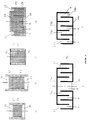
Fig. 1 zeigt eine Ausführungsform der Erfindung, bei der die
Isolierhülle verschraubbar ausgeführt ist: Das metallische
Gehäuse 1 sowie die blanken Enden der Leiterhüllen 2
und des He-Rohres 4 sind von einer Isolatorhülle, bestehend
aus den Teilen 6 und 7, umgeben. In den Teil 6 der Hülle ist
der Einsatz 8 eingesetzt (vorteilhafterweise eingeklebt).
Letzterer könnte sich an einer beliebigen Stelle der Hülle
sowohl im Teil 6 als auch im Teil 7 befinden. Die Teile 6
und 7 sind vorteilhafterweise miteinander verschraubt, so
daß der Teil 6 einfach montiert bzw. abgenommen werden
kann. Das Gewinde zwischen den beiden Hüllenteilen ist so
gedichtet, daß an dieser Stelle auch bei der höchstmöglichen
Spannung im Paschen-Minimum kein Durchschlag erfolgen kann. Fig. 1 shows an embodiment of the invention in which the
Insulation is designed to be screwed: The metallic
Housing 1 and the bare ends of the
Die Montage der Isolation nach Fig. 1 könnte beispielsweise
so erfolgen, daß schon vor der Montage des Gehäuses 1 der
Teil 7 über die Leiter- und Rohrenden aufgeschoben wird.
Nach der Montage der Leiterverbindung, des He-Anschlusses,
einer eventuellen Instrumentierung sowie des Verbindungsgehäuses
würden dann die Teile 6 und 7 vorläufig verschraubt,
in die richtige Lage gebracht, und der Teil 7 mit den
Isolationen 5 der Leiter- bzw. Rohrenden verklebt. Der Teil
6 mit dem Einsatz 8 würde nach dem Aushärten der Klebestellen
endgültig mit dem Teil 7 verschraubt werden.The assembly of the insulation according to Fig. 1 could for example
so that even before the assembly of the housing 1
Die erfindungsgemäße Isolation erfüllt alle drei genannten
Anforderungen. Der Zwischenraum zwischen dem Verbindungsgehäuse
und der Hülle wird über den Einsatz 8 ausreichend
gut evakuiert. Die Öffnung hat den zusätzlichen Vorteil,
daß daran ein Leckdetektor für einen integralen (warmen)
Lecktest des Verbindungsgehäuses angeschlossen werden kann.The insulation according to the invention fulfills all three mentioned
Conditions. The space between the connector housing
and the shell is sufficient over the
In einer anderen möglichen Ausführungsform sind die Teile 6 und 7, wie im Detail "Variante A" der Fig. 1 dargestellt, über eine Flanschverbindung miteinander lösbar verbunden. Die Dichtung zwischen den Flanschen kann geometrisch verschiedenartig geformt, muß aber wiederum "Paschen-dicht" sein.In another possible embodiment, the parts are 6 and 7, as shown in detail "variant A" of FIG. 1, releasably connected to one another via a flange connection. The seal between the flanges can be geometrically different shaped, but must again be "Paschen-dense" his.
Für höhere Spannungen könnte es erforderlich sein, die
Verbindungsstelle zwischen den Hüllenteilen 6 und 7 zu
verkleben. Die "Variante B" in Fig. 1 stellt ein Beispiel
einer einfach lösbaren Klebestelle dar. Dabei werden die
Teile 6 und 7 zusammengefügt und die Verbindungsstelle
beispielsweise mit epoxidharzgetränktem Isolatorgewebe "naß"
umwickelt, so daß ein mit der Hülle fest verbundener Ring 9
entsteht. Anstatt einen Naßwickel herzustellen könnte man
auch einen festen Ring aufkleben. Für eine eventuelle
spätere Demontage müßte nur der Ring 9 abgeschliffen werden.
Beide Hüllenteile wären wieder verwendbar. For higher voltages it may be necessary to use the
Connection point between the
Der Einsatz 8 in der Isolierhülle hat die Aufgabe, den
Stromtransport im ionisierten Gas im "Paschen-Minimum" bei
niedrigen Gasdrücken zu vermeiden bzw. sehr stark zu vermindern.
Als Einsatz 8 kann z.B. ein konventioneller Filter,
z.B. ein HDPE (high density polyethylene)-Filter, verwendet
werden.The
In einer weiteren Ausführungsform wird anstelle des Filters
8 ein Filtersystem, bestehend aus mehreren Teilen,
eingesetzt. Die Fig. 2a und b zeigen solche Filtersysteme,
die aus den Filtern 10 und 11 bestehen, die in ein Isolatorrohr
12 eingeklebt sind. Der Raum zwischen den beiden
Filtern kann mit gasdurchlässigem Schaum, Isolierpulver oder
Glasperlen 13 ausgefüllt sein. Beim Filtersystem der Fig. 2b
wird die Überschlagsstrecke an der Innenwand des Rohres 12
durch Rillen verlängert. Zusätzlich behindern die Rillen
(wegen der wechselnden Winkel der Feldlinien zur Wand)
durchgehende Entladungen. In der Ausführung Fig. 2c besteht
das Filtersystem nur aus Schaum, Pulver oder Glasperlen 14,
die von einem Isolatorrohr 15 und gasdurchlässigen Geweben
oder Sieben 16 eingeschlossen sind.In a further embodiment, instead of the filter
8 a filter system consisting of several parts,
used. 2a and b show such filter systems,
which consist of
Im Filtersystem der Abbildung 2d wird die elektrische Entladung um 180° so umgelenkt, daß sie, in Bezug zum außen anliegenden Feld, teilweise in einem elektrischen Gegenfeld erfolgt und dadurch stark reduziert wird. Dazu werden ein topfförmiger Isolatorteil (19) und ein als Ringgefäß ausgeführter Isolator (20) so ineinandergesteckt, daß die Entladung nacheinander durch den äußeren Ringraum (C), den inneren Ringraum (D) sowie die innere Öffnung des Ringgefäßes (E) - oder umgekehrt - erfolgen muß. Im inneren Ringraum (D) fließt der Entladestrom gegen die außen anliegende Spannung. Der äußere Ringraum (C) sowie die innere Öffnung des Ringgefäßes (E) sind mit einem Filter, Sieb oder Gewebe (17 bzw. 18) abgeschlossen. Der gesamte, aus den drei Teilräumen (C, D, E) bestehende Entladungsraum zwischen den Filtern (bzw. Sieben oder Geweben) kann bei niedrigeren Spannungen leer sein oder ist zur Isolation höherer Spannungen mit Glasperlen, Pulver oder offenporigem Schaum gefüllt. Der Isolatorteil (19) wird entweder nur vom ringförmigen Filter (17) oder von zusätzlichen, den Entladungsraum nicht unterbrechenden Halteelementen in seiner Lage gehalten.In the filter system of Figure 2d, the electrical Discharge deflected by 180 ° so that it, in relation to the outside adjacent field, partly in a counter electric field takes place and is thereby greatly reduced. To do this, be a pot-shaped insulator part (19) and a ring vessel Insulator (20) so that the discharge one after the other through the outer annulus (C) inner annulus (D) and the inner opening of the annular vessel (E) - or vice versa - must be done. In the inner annulus (D) the discharge current flows against the external one Tension. The outer annulus (C) and the inner opening of the ring vessel (E) are with a filter, sieve or fabric (17 or 18) completed. The whole of the three Partial spaces (C, D, E) existing discharge space between the Filters (or sieves or fabrics) can be used at lower ones Voltages be empty or is used to isolate higher voltages with glass beads, powder or open-cell foam filled. The isolator part (19) is either only from annular filter (17) or additional, the discharge space non-interrupting holding elements in its Location held.
In konsequenter Fortführung dieser Idee der Umlenkung des Durchschlagsweges sind auch Filteranordnungen möglich, bei denen weitere Ringräume hinzugefügt werden, in denen eine Entladung mehrfach die Richtung zum elektrischen Feld wechseln muß. Fig. 2e zeigt eine soiche Anordnung, bei der die Entladerichtung zweimal gegen das Feld gerichtet ist.In a consistent continuation of this idea of redirecting the Breakdown path, filter arrangements are also possible at to which further ring spaces are added, in which one Discharge change the direction to the electric field several times got to. Fig. 2e shows such an arrangement in which the unloading direction twice against the field.
Die im Querschnitt cezeigten Filtersysteme der Fig. 2a bis 2e
müssen selbstverständlich nicht eine runde, sondern können
beliebige Grundrißformen besitzen. Beispielsweise können die
Figuren 2d und 2e auch als Schnitte durch quaderförmige
Anordnungen gesehen werden, bei denen die Teile 19 und 20 bzw.
19a und 20a sowie der dann in zwei rechteckige Teile
zerfallende Filter 17 und ebenfalls rechteckige Filter 18 über
zwei Seitenwände so verklebt sind, daß der Entladeraum 21 bzw.
21a seitlich geschlossen ist.The filter systems shown in cross section ce. 2a to 2e
need not be a round, of course, but can
have any floor plan. For example, the
Figures 2d and 2e also as sections through cuboid
Arrangements can be seen in which the
Eine andere Ausführungsform einer solchen quaderförmigen
Anordnung ist in Fig. 2f gezeigt. Die kammförmigen Teile 19b
und 20b sowie die rechteckigen Filter 17b und 18b werden über
Seitenwände so verklebt, daß ein mäanderförmiger Entladungsraum
21b entsteht.Another embodiment of such a cuboid
The arrangement is shown in Fig. 2f. The comb-shaped
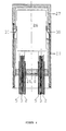
Eine weitere Ausführungsform der Erfindung ist in Fig. 3
dargestellt. In diesem Fall besitzt das Gehäuse 22 Leiter
und/oder Rohranschlüsse auf zwei Seiten; es ist von der
Isolatorhülle bestehend aus den Teilen 23, 24 und 25 umgeben.
Der Filter 8 ist in den Teil 24 eingesetzt, er könnte
sich aber wiederum an einer beliebigen Stelle der Hülle
befinden. Der Durchmesser des Teils 24 ist größer als der
des Teils 25.Another embodiment of the invention is shown in FIG. 3
shown. In this case, the housing has 22 conductors
and / or pipe connections on two sides; it is from the
Insulator cover consisting of
Die Montage dieser Isolation erfolgt im wesentlichen so, daß
zuerst der Teil 23 und danach der Teil 25 über die Leiter
und Rohre auf der oberen Seite des Gehäuses 22 und sodann
der Teil 24 über die Leiter und Rohre auf der unteren Seite
geschoben werden. Dann werden die Anschlüsse hergestellt,
das Gehäuse 22 montiert und die Teile 24 und 25 durch vorläufiges
Verschrauben mit Teil 23 in die richtige Lage
gebracht und danach verklebt. Bei der Endmontage wird das
Rohr 23 gleichzeitig mit den Teilen 24 und 25 über entsprechende
Dichtmaterialien verschraubt.The installation of this insulation is essentially such that
Anstelle der gezeichneten Gewinde können auf beiden oder auch nur auf einer Seite Flanschverbindungen oder Verklebung etwa entsprechend Variante A bzw. Variante B in Fig. 1 verwendet werden.Instead of the drawn thread you can use either or flange connections or gluing only on one side approximately according to variant A or variant B in FIG. 1 be used.
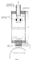
Eine weitere Ausführungsform der Erfindung ist in Fig. 4
dargestellt. In dieser Variante werden die Schwachstellen
der Isolation, nämlich der Filter 8 und das Gewinde zwischen
den Hüllenteilen 27 und 28, durch einen Potentialschirm 29
so abgeschirmt, daß diese Schwachstellen in Bereichen mit
niedrigen elektrischen Feldstärken zu liegen kommen. Der
elektrische Kontakt zwischen dem Verbindungsgehäuse 26 und
dem Potentialschirm 29 wird über Federelemente 30 hergestellt
Diese Federn 30 sind mit dem Potentialschirm 29 fest
verbunden und bilden mit dem Gehäuse 26 einen druckbelasteten
Schleifkontakt. Die Montage dieser Isolation
entspricht der der Isolation nach Fig. 1. Another embodiment of the invention is shown in FIG. 4
shown. In this variant, the weak points
the insulation, namely the
Am Gehäuse 26 des Beispiels Fig. 4 könnten selbstverständlich
entsprechend Fig. 1 auch Helium- oder
Instrumentierungsrohre angeschlossen werden, es wäre dafür
trotz des Filters 8 ausreichend Platz im Teil 28 vorhanden.On the
Weiter ist es möglich, einen den Teilen 29 und 30
entsprechenden Potentialschirm auch in einer Anordnung wie
in Fig. 3 zu verwenden. Dazu müßte in ein oben und unten
verlängertes Rohr 23 ein entsprechend langer Potentialschirm,
der sowohl das obere als auch untere Gewinde und den
Filter abschirmt, eingesetzt werden.It is also possible to use
Die erfindungsgemäße Hochspannungsisolation für Einrichtungen in Gasen bei niedrigen Drücken könnte beim geplanten Stellarator W7-X zur "Paschen-dichten" Isolierung der Spulenanschlüsse eingesetzt werden. Dort werden etwa 500 solcher Isolationen für Prüfspannungen zwischen 10 und 20 kV benötigt. Der Test- und Demonstrationskryostat für W7-X wird etwa 50 Leiter-Verbindungstöpfe enthalten.The high-voltage insulation for devices according to the invention in gases at low pressures could be at the planned time Stellarator W7-X for "Paschen-tight" insulation of the Coil connections are used. There will be about 500 such isolations for test voltages between 10 and 20 kV needed. The test and demonstration cryostat for W7-X will contain about 50 conductor connection pots.
Weitere potentielle Anwendungsmöglichkeiten sind bei ITER und allen Fusions- oder anderen Projekten gegeben, bei denen Magnetspulen mit intern gekühlten Supraleitern oder normalleitenden Kabeln verwendet werden, und die im Betrieb von Vakuum umgeben sind.Other potential applications are at ITER and any merger or other project where Magnetic coils with internally cooled superconductors or normally conductive Cables are used, and those in the operation of Vacuum are surrounded.
Die Erfindung wurde in einer Ausführung nach Fig. 5 erprobt. Die Gasatmosphäre bestand aus Helium mit verschiedenen Drücken im Bereich von 10-4 mbar bis 0,4 bar, so daß die Isolation mit Sicherheit den Bedingungen des Paschen-Minimums ausgesetzt war.The invention was tested in an embodiment according to FIG. 5. The gas atmosphere consisted of helium with various pressures in the range from 10 -4 mbar to 0.4 bar, so that the insulation was certainly exposed to the conditions of the Paschen minimum.
Die Isolierhülle war aus GFK-Teilen zusammengeklebt bzw. verschraubt, die beiden Gewinde waren mit Teflonbändern abgedichtet. Das Filtersystem bestand aus einer Kombination von zwei eingeklebten HDPE-Filtern mit Porengrößen von ca. 250 µm und dazwischenliegenden Glasperlen mit Durcnmessern von 200 µm bis 300 µm. Die gesamte Anordnung war konzentrisch in einem zylindrischen, geerdeten Vakuumgefäß aus Metall mit einem Innendurchmesser von 315 mm angeordnet.The insulating sleeve was glued together from GRP parts or screwed, the two threads were with Teflon tapes sealed. The filter system consisted of a combination of two glued-in HDPE filters with pore sizes of approx. 250 µm and glass beads in between with diameters from 200 µm to 300 µm. The whole arrangement was concentric in a cylindrical, earthed vacuum vessel Metal arranged with an inner diameter of 315 mm.
Mit der gezeigten Anordnung wurden je nach Gasdruck sowohl langsam als auch stoßweise aufgebrachte Gleichspannungen zwischen 8 kV und 12 kV mit Standzeiten von einer Minute erreicht.With the arrangement shown were both depending on the gas pressure DC voltages applied slowly as well as intermittently between 8 kV and 12 kV with a downtime of one minute reached.
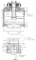
Fig. 6 zeigt einen experimentellen Aufbau zur Erprobung einer erfindungsgemäßen Vorrichtung mit einer weiteren Filteranordnung. Die Schnittdarstellungen in Fig. 6 sind zur Verdeutlichung der Größenverhältnisse mit Maßangaben (Millimeter) versehen. Die Maßancaben in Figur 5 und Figur 6 repräsentieren lediglich beispielhaft spezielle Ausführungsformen und können an die Dimensionen eines konkret realisierten Aufbaus angepaßt werden. Die Anordnung nach Fig. 6 wurde in derselben Versuchseinrichtung bei einer Temperatur von ca. 80 K und bei Heliumatmosphäre mit Drücken wie oben erfolgreich bis 16 kV getestet. Die Filteranordnung entspricht der Fig. 2d. Sie war mit Glasperlen gefüllt, und es wurde dasselbe HDPE-Filtermaterial verwendet. Die Filteranordnung kann wie in Fig. 6 unten dargestellt mit inneren Abstandshaltern z.B. in Form von mehreren Stiften versehen sein, die zwischen den verschiedenen Seitenwänden (Isolatorelemente) der Filteranordnung vorgesehen sind, um die Stabilität der Filteranordnung zu erhöhen. Die Isolierhülle wurde gemäß Fig. 1, Variante A, mit einem flachen Teflonring gedichtet (Flanschdichtung am oberen Ende). Es konnte gezeigt werden, daß die Filteranordnung für die beschriebenen Zwecke ausreichend gasdurchlässsig ist und das Abpumpen der Einrichtung auf Hochvakuum ohne wesentliche Verzögerung erlaubt.Fig. 6 shows an experimental setup for testing a Device according to the invention with a further filter arrangement. The sectional views in Fig. 6 are for Clarification of the size relationships with dimensions (millimeters) Mistake. The dimensions in Figure 5 and Figure 6 represent specific embodiments only by way of example and can be specific to the dimensions of a realized structure can be adjusted. The arrangement according to Fig. 6 was in the same test facility at one temperature of approx. 80 K and in a helium atmosphere with pressures as above successfully tested up to 16 kV. The filter arrangement corresponds 2d. It was filled with glass beads and it was uses the same HDPE filter material. The filter arrangement can, as shown in Fig. 6 below, with inner spacers e.g. be provided in the form of several pens that between the different side walls (insulator elements) of the Filter arrangement are provided to ensure the stability of the filter arrangement to increase. The insulating sleeve was made according to FIG. 1, Variant A, sealed with a flat Teflon ring (flange seal at the upper end). It could be shown that the Filter arrangement sufficient for the purposes described is gas permeable and the pumping of the device High vacuum allowed without significant delay.
Mit einem einzelnen HDPE-Filter mit einem Durchmeser von 30 mm, einer Dicke von 6,35 mm und einer Porengröße von 125 µm wurde eine Durchschlagsspannung von ca. 2 kV erreicht.With a single HDPE filter with a diameter of 30 mm, a thickness of 6.35 mm and a pore size of A breakdown voltage of approx. 2 kV became 125 µm reached.
Claims (18)
- High voltage insulation for insulating cable connections and/or current and/or coolant connections of vacuum insulated magnet coils, especially super-conducting magnet coils with internal cooled cables (2, 3), characterized in that the region to be insulated is surrounded by an insulating sheath (6, 7; 23, 24, 25), while the sheath wall has an opening and a gas-permeable and electrically insulating insert (8, 10-21) is fitted in the opening for evacuation of the interior of the sheath.
- High voltage insulation according to claim 1, characterized in that the insert (8, 10-21) is a filter (8) or a filter system (10-13; 14-16; 17-21).
- High voltage insulation according to claim 1 or 2, characterized in that the connection between the cables or the current connection of the magnet coil is located in a housing (1) and/or the coolant inlet or outlet is effected through such a housing (1) and the cable sheathes (2) and/or the coolant line (4) are welded to the housing (1).
- High voltage insulation according to one or more of the preceding claims, characterized by a first, flat sheath wall part (7) and a second, pot-like sheath part (6).
- High voltage insulation according to one or more of claims 1 to 3, characterized by two flat sheath wall parts (24, 25) and a tubular sheath part (23).
- High voltage insulation according to claim 4 or 5, characterized in that the sheath wall parts (7; 24, 25) have a plurality of passages for the current and coolant connections.
- High voltage insulation according to one or both of claims 4 and 6, characterized in that the sheath wall part (7) and the sheath part (6) can be screwed together.
- High voltage insulation according to one or both of claims 5 and 6, characterized in that one or both sheath wall parts (24, 25) and the sheath part (23) can be screwed together.
- High voltage insulation according to one or both of claims 4 and 6, characterized in that the sheath wall part (7) and the sheath part (6) are connected together releasably via a flange connection.
- High voltage insulation according to one or both of claims 5 and 6, characterized in that one or both sheath wall parts (24, 25) and the sheath part (23) are connected together releasably via a flange connection.
- High voltage insulation according to one or both of claims 4 and 6, characterized in that the sheath wall part (7) and the sheath part (6) are bonded together.
- High voltage insulation according to one or both of claims 5 and 6, characterized in that one or both sheath wall parts (24, 25) and the sheath part (23) are bonded together.
- High voltage insulation according to one or more of claims 2 to 12, characterized in that the filter system (10-13) has two filters (10) and (11), which are enclosed and spaced from one another in an insulating tube (12), the space between them being filled with an insulating medium (13) such gas-permeable foam, powder or glass beads.
- High voltage insulation according to one or more of claims 2 to 12, characterized in that the filter system (14-16) contains gasp-permeable fabrics or sieves which are attached to an insulating tube (15) and spaced from one another, the space between them being filled with an insulating medium (14) such gas-permeable foam, powder or glass beads.
- High voltage insulation according to one or more of claims 2 to 12, characterized in that the filter system (17-21) consists of two insulator elements (19, 19a, 19b, 20, 20a, 20b), which have the form of a vessel open on one side, with bottom, side and partition walls and their open sides so fitted into one another that the voltage discharge path consists of meandering discharge spaces (C, D, E) connected in series, wherein the outer space (C) is closed by a filter, sieve or fabric (17) and an inner space (E) of the insulator element (20, 20a) or an outer space of the insulator element (19b) is closed with a filter, sieve or fabric (18) and the intervening space between the filters or sieves or fabrics (17, 18) is either empty or filled with an insulating medium (21), such as gas permeable foam, powder or glass beads.
- High voltage insulation according to claim 15, characterized in that the bottom wall of the insulating elements (19, 19a, 20, 20a) has a substantially circular shape, wherein the first insulator element is made like a pot (19) or in the form of a pot (19a) with an annular partition wall and the second insulator element is made as an annular vessel (20) or an annular vessel (20a) with an annular partition wall, so that annular discharge spaces (C, D) and a tubular discharge space (E) are formed.
- High voltage insulation according to claim 15, characterized in that the bottom walls of the insulator elements (19b, 20b) have a substantially rectangular shape and the side and partition walls are arranged substantially perpendicular thereto.
- High voltage insulation according to one or more of the preceding claims, characterized in that the weak points in the insulation are so shielded by a potential screen (29) that they come to lie in regions with low electric field strengths.
Applications Claiming Priority (3)
| Application Number | Priority Date | Filing Date | Title |
|---|---|---|---|
| DE19504857A DE19504857C2 (en) | 1995-02-14 | 1995-02-14 | Gas permeable high voltage insulation |
| DE19504857 | 1995-02-14 | ||
| PCT/EP1996/000559 WO1996025751A1 (en) | 1995-02-14 | 1996-02-09 | Gas-permeable high-voltage insulation |
Publications (2)
| Publication Number | Publication Date |
|---|---|
| EP0809852A1 EP0809852A1 (en) | 1997-12-03 |
| EP0809852B1 true EP0809852B1 (en) | 2000-01-19 |
Family
ID=7753905
Family Applications (1)
| Application Number | Title | Priority Date | Filing Date |
|---|---|---|---|
| EP96904049A Expired - Lifetime EP0809852B1 (en) | 1995-02-14 | 1996-02-09 | Gas-permeable high-voltage insulation |
Country Status (3)
| Country | Link |
|---|---|
| EP (1) | EP0809852B1 (en) |
| DE (2) | DE19504857C2 (en) |
| WO (1) | WO1996025751A1 (en) |
Families Citing this family (1)
| Publication number | Priority date | Publication date | Assignee | Title |
|---|---|---|---|---|
| CN114171254A (en) * | 2021-12-10 | 2022-03-11 | 国网上海市电力公司 | Integrated joint topology suitable for high-temperature superconducting urban power cable |
Family Cites Families (3)
| Publication number | Priority date | Publication date | Assignee | Title |
|---|---|---|---|---|
| JPS60200579A (en) * | 1984-03-26 | 1985-10-11 | Mitsubishi Electric Corp | Superconductive device |
| EP0464498A3 (en) * | 1990-06-22 | 1992-03-04 | Kabushiki Kaisha Toshiba | Current lead |
| US5623240A (en) * | 1992-10-20 | 1997-04-22 | Sumitomo Heavy Industries, Ltd. | Compact superconducting magnet system free from liquid helium |
-
1995
- 1995-02-14 DE DE19504857A patent/DE19504857C2/en not_active Expired - Fee Related
-
1996
- 1996-02-09 EP EP96904049A patent/EP0809852B1/en not_active Expired - Lifetime
- 1996-02-09 WO PCT/EP1996/000559 patent/WO1996025751A1/en active IP Right Grant
- 1996-02-09 DE DE59604231T patent/DE59604231D1/en not_active Expired - Fee Related
Also Published As
| Publication number | Publication date |
|---|---|
| WO1996025751A1 (en) | 1996-08-22 |
| DE19504857A1 (en) | 1996-08-22 |
| DE59604231D1 (en) | 2000-02-24 |
| DE19504857C2 (en) | 2002-02-07 |
| EP0809852A1 (en) | 1997-12-03 |
Similar Documents
| Publication | Publication Date | Title |
|---|---|---|
| DE2317853C2 (en) | Electrical implementation | |
| DE2348895C2 (en) | Connection for power cables | |
| CH664040A5 (en) | PRESSURE GAS-INSULATED CURRENT TRANSFORMER. | |
| DE2021066A1 (en) | Encapsulated gas-insulated high-voltage line | |
| EP0215286A1 (en) | High power pulse transformer for short high-voltage and/or high-current pulses | |
| EP0388689A2 (en) | Axial electric wound capacitor | |
| EP0809852B1 (en) | Gas-permeable high-voltage insulation | |
| DE4319682A1 (en) | High voltage insulator for transmission of cooling fluid in HV exterior electrical system | |
| EP1844482B1 (en) | Toroidal core current transformer | |
| DE1807996A1 (en) | Single conductor converter | |
| DE2233217A1 (en) | DRUM LENGTH OF A GAS-INSULATED HIGH-VOLTAGE CABLE | |
| EP0653767B1 (en) | Transformer for medium voltage | |
| DE3542054C2 (en) | End closure especially for plastic insulated high voltage cables | |
| EP2923423A1 (en) | Fluid-tight line feedthrough | |
| DE2327629A1 (en) | FEED-THROUGH INSULATOR FOR HIGH VOLTAGE DEVICES AND METHODS FOR ITS MANUFACTURING | |
| DE3512657C2 (en) | ||
| DE2624325A1 (en) | Through bushing joining ducts with dissimilar dielectrics - are contoured to give constant electric stress on both sides | |
| WO2019020311A1 (en) | Insertable high-voltage feed-through and electrical device comprising the insertable high-voltage feed-through | |
| DE202004007187U1 (en) | Test sealing end for a superconductive cable has a double-walled tube and a cable core surrounded by a cryostatic temperature regulator | |
| DE102012200502A1 (en) | Housing segment and housing section for a switchgear and method for its manufacture | |
| DE702787C (en) | Power transformer | |
| DE3312025C2 (en) | ||
| DE19933352C1 (en) | Axial, cryogenically suitable potential isolator | |
| DE3843907A1 (en) | Thermal insulation | |
| EP3993193A1 (en) | Gas-insulated high-voltage plug connection, comprising a pressure-carrying enclosure, whereby a first part of the enclosure forms a connecting socket and a second part of the enclosure forms a plug |
Legal Events
| Date | Code | Title | Description |
|---|---|---|---|
| PUAI | Public reference made under article 153(3) epc to a published international application that has entered the european phase |
Free format text: ORIGINAL CODE: 0009012 |
|
| 17P | Request for examination filed |
Effective date: 19970716 |
|
| AK | Designated contracting states |
Kind code of ref document: A1 Designated state(s): DE FR GB IT |
|
| GRAG | Despatch of communication of intention to grant |
Free format text: ORIGINAL CODE: EPIDOS AGRA |
|
| 17Q | First examination report despatched |
Effective date: 19990427 |
|
| GRAG | Despatch of communication of intention to grant |
Free format text: ORIGINAL CODE: EPIDOS AGRA |
|
| GRAH | Despatch of communication of intention to grant a patent |
Free format text: ORIGINAL CODE: EPIDOS IGRA |
|
| GRAH | Despatch of communication of intention to grant a patent |
Free format text: ORIGINAL CODE: EPIDOS IGRA |
|
| GRAA | (expected) grant |
Free format text: ORIGINAL CODE: 0009210 |
|
| AK | Designated contracting states |
Kind code of ref document: B1 Designated state(s): DE FR GB IT |
|
| REF | Corresponds to: |
Ref document number: 59604231 Country of ref document: DE Date of ref document: 20000224 |
|
| ITF | It: translation for a ep patent filed |
Owner name: BARZANO' E ZANARDO ROMA S.P.A. |
|
| ET | Fr: translation filed | ||
| GBT | Gb: translation of ep patent filed (gb section 77(6)(a)/1977) |
Effective date: 20000410 |
|
| PLBE | No opposition filed within time limit |
Free format text: ORIGINAL CODE: 0009261 |
|
| STAA | Information on the status of an ep patent application or granted ep patent |
Free format text: STATUS: NO OPPOSITION FILED WITHIN TIME LIMIT |
|
| 26N | No opposition filed | ||
| PGFP | Annual fee paid to national office [announced via postgrant information from national office to epo] |
Ref country code: GB Payment date: 20010207 Year of fee payment: 6 |
|
| PGFP | Annual fee paid to national office [announced via postgrant information from national office to epo] |
Ref country code: FR Payment date: 20010227 Year of fee payment: 6 |
|
| PGFP | Annual fee paid to national office [announced via postgrant information from national office to epo] |
Ref country code: DE Payment date: 20010411 Year of fee payment: 6 |
|
| REG | Reference to a national code |
Ref country code: GB Ref legal event code: IF02 |
|
| PG25 | Lapsed in a contracting state [announced via postgrant information from national office to epo] |
Ref country code: GB Free format text: LAPSE BECAUSE OF NON-PAYMENT OF DUE FEES Effective date: 20020209 |
|
| PG25 | Lapsed in a contracting state [announced via postgrant information from national office to epo] |
Ref country code: DE Free format text: LAPSE BECAUSE OF NON-PAYMENT OF DUE FEES Effective date: 20020903 |
|
| GBPC | Gb: european patent ceased through non-payment of renewal fee |
Effective date: 20020209 |
|
| PG25 | Lapsed in a contracting state [announced via postgrant information from national office to epo] |
Ref country code: FR Free format text: LAPSE BECAUSE OF NON-PAYMENT OF DUE FEES Effective date: 20021031 |
|
| REG | Reference to a national code |
Ref country code: FR Ref legal event code: ST |
|
| PG25 | Lapsed in a contracting state [announced via postgrant information from national office to epo] |
Ref country code: IT Free format text: LAPSE BECAUSE OF NON-PAYMENT OF DUE FEES;WARNING: LAPSES OF ITALIAN PATENTS WITH EFFECTIVE DATE BEFORE 2007 MAY HAVE OCCURRED AT ANY TIME BEFORE 2007. THE CORRECT EFFECTIVE DATE MAY BE DIFFERENT FROM THE ONE RECORDED. Effective date: 20050209 |