EP0809745B1 - Fixation de porte - Google Patents
Fixation de porte Download PDFInfo
- Publication number
- EP0809745B1 EP0809745B1 EP96901314A EP96901314A EP0809745B1 EP 0809745 B1 EP0809745 B1 EP 0809745B1 EP 96901314 A EP96901314 A EP 96901314A EP 96901314 A EP96901314 A EP 96901314A EP 0809745 B1 EP0809745 B1 EP 0809745B1
- Authority
- EP
- European Patent Office
- Prior art keywords
- section
- pivoting rod
- securing
- flap
- holder according
- Prior art date
- Legal status (The legal status is an assumption and is not a legal conclusion. Google has not performed a legal analysis and makes no representation as to the accuracy of the status listed.)
- Expired - Lifetime
Links
- 238000004519 manufacturing process Methods 0.000 description 2
- 208000000260 Warts Diseases 0.000 description 1
- 230000006978 adaptation Effects 0.000 description 1
- 238000006073 displacement reaction Methods 0.000 description 1
- 238000003780 insertion Methods 0.000 description 1
- 230000037431 insertion Effects 0.000 description 1
- 239000002991 molded plastic Substances 0.000 description 1
- 201000010153 skin papilloma Diseases 0.000 description 1
Images


Classifications
-
- E—FIXED CONSTRUCTIONS
- E05—LOCKS; KEYS; WINDOW OR DOOR FITTINGS; SAFES
- E05C—BOLTS OR FASTENING DEVICES FOR WINGS, SPECIALLY FOR DOORS OR WINDOWS
- E05C17/00—Devices for holding wings open; Devices for limiting opening of wings or for holding wings open by a movable member extending between frame and wing; Braking devices, stops or buffers, combined therewith
- E05C17/02—Devices for holding wings open; Devices for limiting opening of wings or for holding wings open by a movable member extending between frame and wing; Braking devices, stops or buffers, combined therewith by mechanical means
- E05C17/04—Devices for holding wings open; Devices for limiting opening of wings or for holding wings open by a movable member extending between frame and wing; Braking devices, stops or buffers, combined therewith by mechanical means with a movable bar or equivalent member extending between frame and wing
- E05C17/045—Hinges for the movable bar
-
- E—FIXED CONSTRUCTIONS
- E05—LOCKS; KEYS; WINDOW OR DOOR FITTINGS; SAFES
- E05D—HINGES OR SUSPENSION DEVICES FOR DOORS, WINDOWS OR WINGS
- E05D7/00—Hinges or pivots of special construction
- E05D7/10—Hinges or pivots of special construction to allow easy separation or connection of the parts at the hinge axis
- E05D7/1005—Hinges or pivots of special construction to allow easy separation or connection of the parts at the hinge axis by axially moving free pins, balls or sockets
-
- F—MECHANICAL ENGINEERING; LIGHTING; HEATING; WEAPONS; BLASTING
- F16—ENGINEERING ELEMENTS AND UNITS; GENERAL MEASURES FOR PRODUCING AND MAINTAINING EFFECTIVE FUNCTIONING OF MACHINES OR INSTALLATIONS; THERMAL INSULATION IN GENERAL
- F16B—DEVICES FOR FASTENING OR SECURING CONSTRUCTIONAL ELEMENTS OR MACHINE PARTS TOGETHER, e.g. NAILS, BOLTS, CIRCLIPS, CLAMPS, CLIPS OR WEDGES; JOINTS OR JOINTING
- F16B39/00—Locking of screws, bolts or nuts
- F16B39/02—Locking of screws, bolts or nuts in which the locking takes place after screwing down
-
- E—FIXED CONSTRUCTIONS
- E05—LOCKS; KEYS; WINDOW OR DOOR FITTINGS; SAFES
- E05Y—INDEXING SCHEME ASSOCIATED WITH SUBCLASSES E05D AND E05F, RELATING TO CONSTRUCTION ELEMENTS, ELECTRIC CONTROL, POWER SUPPLY, POWER SIGNAL OR TRANSMISSION, USER INTERFACES, MOUNTING OR COUPLING, DETAILS, ACCESSORIES, AUXILIARY OPERATIONS NOT OTHERWISE PROVIDED FOR, APPLICATION THEREOF
- E05Y2900/00—Application of doors, windows, wings or fittings thereof
- E05Y2900/20—Application of doors, windows, wings or fittings thereof for furniture, e.g. cabinets
-
- F—MECHANICAL ENGINEERING; LIGHTING; HEATING; WEAPONS; BLASTING
- F16—ENGINEERING ELEMENTS AND UNITS; GENERAL MEASURES FOR PRODUCING AND MAINTAINING EFFECTIVE FUNCTIONING OF MACHINES OR INSTALLATIONS; THERMAL INSULATION IN GENERAL
- F16B—DEVICES FOR FASTENING OR SECURING CONSTRUCTIONAL ELEMENTS OR MACHINE PARTS TOGETHER, e.g. NAILS, BOLTS, CIRCLIPS, CLAMPS, CLIPS OR WEDGES; JOINTS OR JOINTING
- F16B37/00—Nuts or like thread-engaging members
- F16B37/14—Cap nuts; Nut caps or bolt caps
Definitions
- the invention relates to a flap holder for attachment between a Furniture body and a furniture flap with a swivel rod on the one hand articulated by means of a bearing pin on a facing section of a foot part stored and secured to it with a securing element, the The foot part is in turn fixed to the furniture flap and the other hand articulated is connected to the furniture body.
- a flap holder of this type is known, for example, in DE 26 48 117 A1 expelled.
- this known flap holder is for securing the pivot rod a securing element in the form of a spring arrangement on the foot part Spring wire provided.
- the spring arrangement has two free legs, which in engage an annular groove on a protruding portion of the journal, so that the journal must have an appropriate adjustment.
- the invention has for its object a flap holder of the type described Art to design so that the assembly of the fuse element the flap holder on the one hand and the flap holder on the preassembled foot part on the other hand can be done easily and quickly.
- the securing element on its by the Bearing journal facing away from the swivel rod or the facing Section of the foot part is held displaceably by means of a guide piece and has a securing section on its side facing the bearing journal, the swivel rod and the facing section when assembled of the foot part in the area of the bearing pin.
- the securing element can be simple and can be easily pushed onto the swivel rod.
- the flap holder prepared in this way can be mounted on the furniture after the foot part is screwed on separately is to be used on the journal without effort, whereby the bearing pin is optionally provided on the foot part or the swivel axis can be.
- the securing element only needs along the pivot rod or, if it is attached to the foot part, along that facing the bearing rod Section to be pushed towards the trunnion.
- the securing section in the overlap area of the swivel rod and the facing section of the foot section over this section or pushed the swivel rod so that the two hinged together Parts are fixed axially with respect to the journal.
- An embodiment such that the guide piece is continuous is advantageous Image with a cross section of the swivel rod or section of the foot part has adjusted internal width and that the securing section has a resilient element, which in the assembled state in the overlap area the swivel rod and the section over the outside of the section or the swivel rod is pushed.
- the resilient element delivers here a holding force, whereby the securing element is pushed in its Location is held. This can be provided to facilitate postponement be that the resilient element has a run-up slope at its free end.
- it is advantageous if it at its the section of the foot part or the swivel rod facing inside has a locking heel with which it can be snapped behind a protrusion of the bearing journal.
- the securing section has at least one rigid holding leg with its inside in the overlap area on the section of the foot part or the swivel rod is present.
- a suitable embodiment is such that two rigid holding legs are provided, which are at least about the diameter of the overhang of the Bearing pins are spaced apart.
- the securing element is chamfered on the insertion side at the edge of the receptacle is, it can be particularly easy on the swivel rod or this facing section of the foot section.
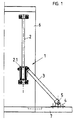
- a flap holder 1 is shown in the form of a brake flap holder.
- a Brake rod 2 with a brake housing 2.1 is vertical on a furniture wall 6 attached.
- One side of a swivel rod 3 is on the brake housing 2.1 articulated, while the other side is articulated on a foot part 4, which in turn is attached to a furniture flap 7.
- a securing element 5 is pushed on, so that the pivot rod 3 and the base 4 are immovable in the axial direction in hinged connection are held together.
- 2A to 2C is the articulated connection between the pivot rod 3 and the foot part 4 reproduced in more detail.
- 2A shows the swivel rod 3 and the foot part 4 before assembly.
- the foot part 4 is with a Fastening part 4.2 before the articulated connection with the swivel rod 3 the furniture flap 7 attached, making handling easy.
- the securing element 5 is pushed away from the bearing pin 3.1 along the pivot rod 3.
- FIG. 2B is the articulated connection between the pivot rod 3 and the Foot part 4 made and the securing element 5 is over the overlap area pushed between the pivot rod 3 and the foot part 4 and overlaps the pin 3.1, which is inserted into the bore 4.3.
- the one at the The part of the securing element 5 that has been pushed on has three Legs that are separated by two slits.
- the middle leg is designed as a resilient element 5.3 so that it has a projection of the bearing pin 3.1 can be pushed, as in particular in FIG. 2C can be seen, which shows the fuse element 5 cut. To this way, the swivel rod 3 cannot move axially from the foot part 4 be moved away, but is securely articulated on this.
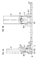
- 3A and 3B is the securing of the articulated connection between the Swivel rod 3 and the section 4.1 of the foot part 4 by means of the securing element 5 shown enlarged.
- the securing element 5 is also here pushed onto the swivel rod 3 and overlaps with its middle leg, which is designed as a resilient element 5.3, the bearing pin 3.1.
- the resilient element 5.3 has at its free end a run-up slope 5.31 and engages behind with a snap-in heel 5.32 when pushed over the facing side of section 4.1 protruding trunnion 3.1 circumferentially, so that the securing element 5 only after lifting the resilient element 5.3 can be pushed back on the swivel rod 3 to the to release articulated connection.
- 3A is a guide piece 5.1 recognizable with which the securing element 5 on the pivot rod 3 slidably is fixed, wherein in the guide piece 5.1 to the cross section of the Guide rod adapted receptacle 5.2 is provided.
- 3B is beyond can be seen that the lower part of the securing element 5, the one securing section 5.4 forms, on both sides of the resilient element already in the 2A to 2C addressed leg in the form of Holding leg 5.41.
- the holding legs 5.41 are relatively rigid and so far distances itself that, when pushed open, to the right and left of the Place the protrusion of the bearing pin 3.1 on the section 4.1 of the foot part 4. This results in an improved hold against axial displacement of the swivel rod 3 with respect to the foot part 4.
- FIGS. 3A and 3B show a further exemplary embodiment of a securing element 5 ', which is an unchanged assembly on the left or right side of the Furniture flap 7 allows.
- the bearing pin 3.1 is on the section 4.1 of the foot part 4 attached and through a corresponding bore Swivel rod 3 pushed.
- the securing element is on the wart as a rivet trained trunnion 3.1 with its resilient element 5.3 'set in correspondingly, as already explained in FIGS. 3A and 3B. Corresponding too Retaining legs as in FIGS. 3A and 3B can be provided.
- the resilient element 5.3 ' is on the resilient element 5.3 'with respect to the support rod 3 opposite side of the securing element 5 at least one rigid Counter leg 5.5 provided with which a further hold against lateral axial Moving the pivot rod 3 relative to the foot part 4 can be achieved.
- the foot part 4, on which the bearing pin 4.1 is attached can now, as shown, can be arranged on the right side of the pivot rod 3, the lenticular Head of the trunnion 3.1 overlapped by the resilient element 5.3 ' is, or it can be arranged on the left side of the pivot rod 3, wherein the end of the pivot pin 3.1 inserted through the swivel rod 3 resilient element 5.3 'is overlapped.
- 5A and 5B is an embodiment for a further securing element 8 shown, which with a guide part 8.1 by means of a receptacle 8.2 is slidably mounted on the section 4.1 of the foot part 4.
- a further securing element 8 shown On the guide section 8.1 is an upward pointing in the direction of the pivot rod 3
- Resilient element 8.3 provided in the direction of the resilient element has an inlet rounding or lead-in chamfer, on which the Swivel rod 3, as shown in broken lines, can be inserted until it comes with a bore with the journal 3.1 to cover and on this is attachable. Then the securing element 8 along the section 4.1 of the foot part 4 pushed up, so that the articulated Connection between the pivot rod 3 and the foot part 4 against axial Moving is secured.
- the securing elements described are preferably made of a resistant Molded plastic.
Landscapes
- Engineering & Computer Science (AREA)
- Mechanical Engineering (AREA)
- General Engineering & Computer Science (AREA)
- Pivots And Pivotal Connections (AREA)
- Hinges (AREA)
Claims (8)
- Fixation de porte à monter entre le corps d'un meuble et une porte de meuble avec une tringle de pivotement qui d'une part est au moyen d'un tourillon monté sur un tronçon qui lui fait face d'un élément de pied et y est assujetti à l'aide d'un élément de sécurité, l'élément de pied étant à son tour fixé à la porte du meuble, et qui d'autre part est raccordée de manière articulée au corps du meuble,
caractérisée
en ce que l'élément de sécurité (5, 5') est, du côté non orienté vers le tourillon (3.1), maintenu au moyen d'une pièce de guidage (5.1) de manière coulissante sur la tringle de pivotement (3) ou sur le tronçon (4.1) qui lui fait face de l'élément de pied (4), et en ce que l'élément de sécurité (5, 5'), du côté qui fait face au tourillon, présente un tronçon de sécurité (5.4) qui à l'état assemblé réunit, dans la région du tourillon (3.1), la tringle de pivotement (3) et le tronçon (4.1) de l'élément de pied (4) qui lui fait face. - Fixation de porte suivant la revendication 1,
caractériséeen ce que la pièce de guidage (5.1) présente un logement continu (5.2) avec une largeur intérieure adaptée à la section transversale de la tringle de pivotement (3) ou au tronçon (4.1) de l'élément de pied (4.1), eten ce que le tronçon de sécurité (5.4) présente un élément à ressort (5.3, 5.3') qui, à l'état assemblé est, dans la zone de chevauchement de la tringle de pivotement (3) et du tronçon (4.1), glissé au-dessus de la face extérieure du tronçon (4.1) ou de la tringle de pivotement (3). - Fixation de porte suivant la revendication 1 ou 2,
caractérisée
en ce qu'à son extrémité libre, l'élément à ressort (5.3, 5.3') présente un biseau de butée (5.31, 5.31'). - Fixation de porte suivant la revendication 3,
caractérisée
en ce qu'à son côté intérieur faisant face au tronçon (4.1) de l'élément de pied (4) ou à la tringle de pivotement (3), l'élément à ressort (5.3, 5.3') présente un épaulement d'encliquetage (5.32), par lequel il peut s'encliqueter derrière une surélévation du tourillon (3.1). - Fixation de porte suivant l'une quelconque des revendications de 1 à 4,
caractérisée
en ce que le tronçon de sécurité (5.4) présente au moins une aile de fixation rigide (5.41) qui dans la zone de chevauchement s'applique par sa face intérieure sur le tronçon (4.1) de l'élément de pied (4) ou sur la tringle de pivotement (3). - Fixation de porte suivant la revendication 5,
caractérisée
en ce que deux ailes de fixation rigides (5.41) sont prévues, qui sont distantes l'une de l'autre d'au moins le diamètre de la surélévation du tourillon. - Fixation de porte suivant l'une quelconque des revendications de 2 à 6,
caractérisée
en ce que sur sa face qui par rapport à l'élément à ressort (5.3, 5.3') est opposée à la tringle de pivotement (3), le tronçon de sécurité (5.4) présente une contre-aile (5.5) qui est issue de la pièce de guidage (5.1). - Fixation de porte suivant l'une quelconque des revendications de 2 à 7,
caractérisée
en ce que l'élément de sécurité (5, 5') est biseauté du côté introduction le long du bord du logement (5.2).
Applications Claiming Priority (3)
| Application Number | Priority Date | Filing Date | Title |
|---|---|---|---|
| DE19505164 | 1995-02-16 | ||
| DE19505164A DE19505164C2 (de) | 1995-02-16 | 1995-02-16 | Klappenhalter |
| PCT/EP1996/000232 WO1996025579A1 (fr) | 1995-02-16 | 1996-01-20 | Fixation de porte |
Publications (2)
| Publication Number | Publication Date |
|---|---|
| EP0809745A1 EP0809745A1 (fr) | 1997-12-03 |
| EP0809745B1 true EP0809745B1 (fr) | 1998-08-12 |
Family
ID=7754101
Family Applications (1)
| Application Number | Title | Priority Date | Filing Date |
|---|---|---|---|
| EP96901314A Expired - Lifetime EP0809745B1 (fr) | 1995-02-16 | 1996-01-20 | Fixation de porte |
Country Status (6)
| Country | Link |
|---|---|
| EP (1) | EP0809745B1 (fr) |
| CZ (1) | CZ289809B6 (fr) |
| DE (2) | DE19505164C2 (fr) |
| HU (1) | HUP9702464A3 (fr) |
| PL (1) | PL321568A1 (fr) |
| WO (1) | WO1996025579A1 (fr) |
Family Cites Families (2)
| Publication number | Priority date | Publication date | Assignee | Title |
|---|---|---|---|---|
| DE1946489A1 (de) * | 1969-09-13 | 1971-03-18 | Heinze Fa R | Halter fuer schwenkbare Klappen oder Tueren von Moebeln u.dgl. |
| DE2648117A1 (de) * | 1976-10-23 | 1978-04-27 | Hettich Hetal Werke | Klappenhalter fuer moebel, z.b. tonmoebel |
-
1995
- 1995-02-16 DE DE19505164A patent/DE19505164C2/de not_active Expired - Fee Related
-
1996
- 1996-01-20 WO PCT/EP1996/000232 patent/WO1996025579A1/fr not_active Ceased
- 1996-01-20 CZ CZ19972566A patent/CZ289809B6/cs not_active IP Right Cessation
- 1996-01-20 PL PL96321568A patent/PL321568A1/xx unknown
- 1996-01-20 HU HU9702464A patent/HUP9702464A3/hu unknown
- 1996-01-20 DE DE59600434T patent/DE59600434D1/de not_active Expired - Fee Related
- 1996-01-20 EP EP96901314A patent/EP0809745B1/fr not_active Expired - Lifetime
Also Published As
| Publication number | Publication date |
|---|---|
| CZ256697A3 (cs) | 1998-01-14 |
| HUP9702464A2 (hu) | 1998-04-28 |
| EP0809745A1 (fr) | 1997-12-03 |
| CZ289809B6 (cs) | 2002-04-17 |
| HUP9702464A3 (en) | 1998-09-28 |
| DE19505164C2 (de) | 1996-12-05 |
| WO1996025579A1 (fr) | 1996-08-22 |
| DE59600434D1 (de) | 1998-09-17 |
| DE19505164A1 (de) | 1996-08-22 |
| PL321568A1 (en) | 1997-12-08 |
Similar Documents
| Publication | Publication Date | Title |
|---|---|---|
| DE2819744C2 (de) | Scharnier, insbesondere Brillenscharnier | |
| DE3843095C2 (de) | Befestigungseinrichtung für Verkleidungen | |
| EP0231440A2 (fr) | Pare-soleil pour véhicules | |
| DE60007754T2 (de) | Schneideinsatzsitz | |
| DE29610026U1 (de) | Steck-Kupplung | |
| DE68903777T2 (de) | Schreibgeraet und zusammenbauverfahren. | |
| DE19903014B4 (de) | Hauptzylinder für eine hydraulische Fahrzeugbremsanlage mit verbesserter Rückstellfederfesselung | |
| EP0809745B1 (fr) | Fixation de porte | |
| DE4204630C2 (de) | Kugelraste für die Lagefixierung eines beweglichen Stellelementes | |
| DE2604325C3 (de) | Wischvorrichtung für Scheiben von Kraftfahrzeugen | |
| DE2814995A1 (de) | Laengenjustierbare verbindung fuer verstellgestaenge | |
| EP1099058A1 (fr) | Joint a rotule | |
| DE2550544C3 (de) | Lager, insbesondere Schwenklager für Fahrzeugsonnenblenden | |
| DE1924879A1 (de) | Wischblatteinheit fuer Windschutzscheiben | |
| DE3509230A1 (de) | Schnappzapfen | |
| DE2532204C2 (de) | Clipanordnung für ein Schreibgerät | |
| DE4016202A1 (de) | Scheibenwischer-vorrichtung fuer kraftfahrzeuge mit verbesserten befestigungsmitteln des wischerblatts am scheibenwischerarm | |
| DE7906414U1 (de) | Vorhangstange mit endseitigen wandhaltern | |
| DE19724577C1 (de) | Lenkrolle | |
| DE19812716B4 (de) | Verbindungsstück zum Anlenken eines Wischblattes an einen Wischarm | |
| DE1940125U (de) | Stielbefestigungsvorrichtung fuer besen od. dgl. | |
| DE29911126U1 (de) | Okular-Schutzdeckel für Ferngläser | |
| EP1039196B1 (fr) | Collier de serrage à dispositif de fixation femelle et dispositif de fixation femelle | |
| DE10214605C1 (de) | Kunststoffblende zur Abdeckung von Funktionsteilen eines Kraftfahrzeugsitzes | |
| DE4407153A1 (de) | Kappe zum Abdecken der Schreibspitze eines Handschreibgerätes |
Legal Events
| Date | Code | Title | Description |
|---|---|---|---|
| PUAI | Public reference made under article 153(3) epc to a published international application that has entered the european phase |
Free format text: ORIGINAL CODE: 0009012 |
|
| 17P | Request for examination filed |
Effective date: 19970916 |
|
| AK | Designated contracting states |
Kind code of ref document: A1 Designated state(s): DE GB IE |
|
| GRAG | Despatch of communication of intention to grant |
Free format text: ORIGINAL CODE: EPIDOS AGRA |
|
| GRAG | Despatch of communication of intention to grant |
Free format text: ORIGINAL CODE: EPIDOS AGRA |
|
| GRAH | Despatch of communication of intention to grant a patent |
Free format text: ORIGINAL CODE: EPIDOS IGRA |
|
| 17Q | First examination report despatched |
Effective date: 19980129 |
|
| GRAH | Despatch of communication of intention to grant a patent |
Free format text: ORIGINAL CODE: EPIDOS IGRA |
|
| GRAA | (expected) grant |
Free format text: ORIGINAL CODE: 0009210 |
|
| AK | Designated contracting states |
Kind code of ref document: B1 Designated state(s): DE GB IE |
|
| PG25 | Lapsed in a contracting state [announced via postgrant information from national office to epo] |
Ref country code: GB Free format text: LAPSE BECAUSE OF FAILURE TO SUBMIT A TRANSLATION OF THE DESCRIPTION OR TO PAY THE FEE WITHIN THE PRESCRIBED TIME-LIMIT Effective date: 19980812 |
|
| REF | Corresponds to: |
Ref document number: 59600434 Country of ref document: DE Date of ref document: 19980917 |
|
| REG | Reference to a national code |
Ref country code: IE Ref legal event code: FG4D Free format text: GERMAN |
|
| GBV | Gb: ep patent (uk) treated as always having been void in accordance with gb section 77(7)/1977 [no translation filed] |
Effective date: 19980812 |
|
| PG25 | Lapsed in a contracting state [announced via postgrant information from national office to epo] |
Ref country code: IE Free format text: LAPSE BECAUSE OF NON-PAYMENT OF DUE FEES Effective date: 19990504 |
|
| PLBE | No opposition filed within time limit |
Free format text: ORIGINAL CODE: 0009261 |
|
| STAA | Information on the status of an ep patent application or granted ep patent |
Free format text: STATUS: NO OPPOSITION FILED WITHIN TIME LIMIT |
|
| REG | Reference to a national code |
Ref country code: IE Ref legal event code: FD4D |
|
| 26N | No opposition filed | ||
| PGFP | Annual fee paid to national office [announced via postgrant information from national office to epo] |
Ref country code: DE Payment date: 20060322 Year of fee payment: 11 |
|
| PG25 | Lapsed in a contracting state [announced via postgrant information from national office to epo] |
Ref country code: DE Free format text: LAPSE BECAUSE OF NON-PAYMENT OF DUE FEES Effective date: 20070801 |