EP0809269B1 - Hochspannungs-Leistungsschalter mit zwei antreibbaren Schaltkontaktstücken - Google Patents
Hochspannungs-Leistungsschalter mit zwei antreibbaren Schaltkontaktstücken Download PDFInfo
- Publication number
- EP0809269B1 EP0809269B1 EP97250161A EP97250161A EP0809269B1 EP 0809269 B1 EP0809269 B1 EP 0809269B1 EP 97250161 A EP97250161 A EP 97250161A EP 97250161 A EP97250161 A EP 97250161A EP 0809269 B1 EP0809269 B1 EP 0809269B1
- Authority
- EP
- European Patent Office
- Prior art keywords
- arcing contact
- contact piece
- circuit breaker
- voltage circuit
- drive
- Prior art date
- Legal status (The legal status is an assumption and is not a legal conclusion. Google has not performed a legal analysis and makes no representation as to the accuracy of the status listed.)
- Revoked
Links
- 230000008878 coupling Effects 0.000 claims description 12
- 238000010168 coupling process Methods 0.000 claims description 12
- 238000005859 coupling reaction Methods 0.000 claims description 12
- 238000000034 method Methods 0.000 claims description 5
- 238000010791 quenching Methods 0.000 claims description 2
- 230000000171 quenching effect Effects 0.000 claims description 2
- 239000003989 dielectric material Substances 0.000 claims 3
- 239000011810 insulating material Substances 0.000 description 4
- 230000001133 acceleration Effects 0.000 description 2
- 230000005540 biological transmission Effects 0.000 description 2
- 238000010276 construction Methods 0.000 description 2
- 230000002085 persistent effect Effects 0.000 description 2
- 239000004810 polytetrafluoroethylene Substances 0.000 description 2
- 229920001343 polytetrafluoroethylene Polymers 0.000 description 2
- 238000000926 separation method Methods 0.000 description 2
- 238000007664 blowing Methods 0.000 description 1
- 230000005684 electric field Effects 0.000 description 1
- 238000004146 energy storage Methods 0.000 description 1
- 239000000463 material Substances 0.000 description 1
- 238000003032 molecular docking Methods 0.000 description 1
- 229910052573 porcelain Inorganic materials 0.000 description 1
Images
Classifications
-
- H—ELECTRICITY
- H01—ELECTRIC ELEMENTS
- H01H—ELECTRIC SWITCHES; RELAYS; SELECTORS; EMERGENCY PROTECTIVE DEVICES
- H01H33/00—High-tension or heavy-current switches with arc-extinguishing or arc-preventing means
- H01H33/70—Switches with separate means for directing, obtaining, or increasing flow of arc-extinguishing fluid
- H01H33/88—Switches with separate means for directing, obtaining, or increasing flow of arc-extinguishing fluid the flow of arc-extinguishing fluid being produced or increased by movement of pistons or other pressure-producing parts
- H01H33/90—Switches with separate means for directing, obtaining, or increasing flow of arc-extinguishing fluid the flow of arc-extinguishing fluid being produced or increased by movement of pistons or other pressure-producing parts this movement being effected by or in conjunction with the contact-operating mechanism
- H01H33/901—Switches with separate means for directing, obtaining, or increasing flow of arc-extinguishing fluid the flow of arc-extinguishing fluid being produced or increased by movement of pistons or other pressure-producing parts this movement being effected by or in conjunction with the contact-operating mechanism making use of the energy of the arc or an auxiliary arc
-
- H—ELECTRICITY
- H01—ELECTRIC ELEMENTS
- H01H—ELECTRIC SWITCHES; RELAYS; SELECTORS; EMERGENCY PROTECTIVE DEVICES
- H01H33/00—High-tension or heavy-current switches with arc-extinguishing or arc-preventing means
- H01H33/02—Details
- H01H2033/028—Details the cooperating contacts being both actuated simultaneously in opposite directions
-
- H—ELECTRICITY
- H01—ELECTRIC ELEMENTS
- H01H—ELECTRIC SWITCHES; RELAYS; SELECTORS; EMERGENCY PROTECTIVE DEVICES
- H01H33/00—High-tension or heavy-current switches with arc-extinguishing or arc-preventing means
- H01H33/02—Details
- H01H33/24—Means for preventing discharge to non-current-carrying parts, e.g. using corona ring
- H01H33/245—Means for preventing discharge to non-current-carrying parts, e.g. using corona ring using movable field electrodes
-
- H—ELECTRICITY
- H01—ELECTRIC ELEMENTS
- H01H—ELECTRIC SWITCHES; RELAYS; SELECTORS; EMERGENCY PROTECTIVE DEVICES
- H01H33/00—High-tension or heavy-current switches with arc-extinguishing or arc-preventing means
- H01H33/70—Switches with separate means for directing, obtaining, or increasing flow of arc-extinguishing fluid
- H01H33/7015—Switches with separate means for directing, obtaining, or increasing flow of arc-extinguishing fluid characterised by flow directing elements associated with contacts
- H01H33/7023—Switches with separate means for directing, obtaining, or increasing flow of arc-extinguishing fluid characterised by flow directing elements associated with contacts characterised by an insulating tubular gas flow enhancing nozzle
Definitions
- the invention relates to a high-voltage circuit breaker with a first and a second, coaxial with each other opposite arcing contact piece, between which at a switch-off optionally a switching arc burns and the in the course of a Ausschaltvorganges by a common drive drivable in opposite directions are, wherein the drive movement by a first drive element on the first arcing contact piece and through a second drive element by means of a deflection gear the second arcing contact piece is transmitted and with two persistent contact pieces coaxially surrounding the arcing contact pieces and with an insulating nozzle, with the first arcing contact piece is firmly connected and the the blowing of the switching arc with a quenching gas is used.
- the present invention is based on the object, a High-voltage circuit breaker of the type mentioned above create, structurally simple and inexpensive is and claimed the smallest possible housing size.
- the object is achieved in that the second drive element attached to the insulating nozzle and is driven by this and the deflection gear a Fixed pivotally mounted two-armed lever, to the second drive element and the second arcing contact piece are coupled to coupling points.
- the second drive element on the insulating material is attached, and the insulating nozzle thus even the Transmitting drive power to the second arcing contact, the second drive element can be kept relatively short become.
- the Isolierstoffdüse drives in turn the second drive element, which the drive movement on the behind the second arcing contact piece arranged deflecting transmits. By means of the deflection gear the drive movement is then on the second arcing contact piece transfer.
- the size of such a high-voltage circuit breaker is exactly the size of a corresponding switch, in which only one of the arcing contact pieces can be driven and in which the second drive element and the deflection gear absence.
- the switch can thus the same Isolierstoffgeophuse, for example, used porcelain housing become.
- the second drive element with the arc or with hot extinguishing gas may come into contact, it should come from a arc-resistant material, such as PTFE produced become.
- the distance between the coupling point of the second arcing contact piece and the coupling point of the second drive element, especially under load of the deflection, changeable is.
- a change in the distance between the coupling point the second arcing contact piece and the coupling point the second drive element allows in a simple manner to change the transmission ratio of the reversing gear. Especially with a change in the distance during a transmission of a drive movement via the deflection gear, d. H. under load of the deflection, can the second arcing contact deliberately accelerated or slowed down.
- a coupling point slidably guided in a backdrop.
- a backdrop-like guidance of a docking point in one Long hole provides a reliable connection with the lever Through the slot it is possible in a simple manner, the distance between the coupling points of the second Drive element and the arcing contact piece variable too to change.
- the second drive element radially within the persistent contact pieces is arranged.
- An advantageous embodiment of the invention can provide that at the reversing gear a the second arcing contact piece surrounding field electrode is coupled in the course a switching movement in opposite directions to the second arcing contact piece is movable.
- a further advantageous embodiment of the invention can Provide that the second arcing contact piece and the Field electrode are coupled to the two-armed lever.
- the reversing gear is in the simplest and functionally safe manner feasible.
- the reversing gear from the first arcing contact piece is arranged behind the second arcing contact piece is ensures that both arcing contact pieces at the turn-off, which requires extremely high acceleration be driven by a pulling movement.
- the rest position of the two-armed lever can be a suitable Acceleration profile of the second arcing contact piece be realized during the switch-off.
- a Overlift of the drive can be compensated.
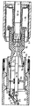
- the figure shows schematically in a longitudinal section a Interrupter unit of a high-voltage circuit breaker.
- the illustrated high voltage circuit breaker has two Arc contact pieces 1, 2, which face each other coaxially.
- the illustration shows a state during the Switching movement shortly before reaching the switch-off state.
- the Arc contact pieces 1, 2 are already separated and between them burns an arc 3.
- the first Arc contact piece 1 is in the direction of the arrow 12, the second arcing contact piece 2 moves in the direction of the arrow 13.
- the first arcing contact piece 1 is hollow and takes in the on state, the pin-shaped second arcing contact piece 2 on.
- the first arcing contact piece 1 is coupled to a contact tube 4, which is also the first drive element does not serve and the drive movement of one transfers illustrated energy storage.
- the first arcing contact 1 carries a multi-part Isolierstoffdüse 9, which in the on state, the second arcing contact piece 2 surrounds and during the turn-off the heated by the arc 3 extinguishing gas passes.
- First can through a channel 14 hot extinguishing gas in a boiler room 15 stream out of it at a suitable time, shortly after Current zero crossing of the alternating current to be switched through the same channel 14 flows back to the arc third to blow and reconsolidation of the switching path too accelerate.
- the free end of the insulating nozzle 9 is guided in a tube 10, which simultaneously forms a field electrode.
- a drive element 5 attached in the form of a rod made of PTFE.
- a ring 16 attached, with one end of the second drive element 5 is screwed.
- the second drive element 5 is the two-armed lever 11 is actuated.
- the rod 5 is pulled in the direction of arrow 17, whereby the lever 11 is pivoted clockwise. hereby is a pulling movement in the direction of arrow 13 on the second arc contact piece 2 transmitted.
- the second arcing contact piece 2 is by means of a Gleitcard arrangement 20 in the axial direction within the field electrode 10 led and contacted.
- the field electrode 10 is in turn in circumferential sliding contacts 21, 22 of the TreasurestromWallet institutions 8 led and contacted.
- the lever 11 of the reversing gear 6 is shown schematically Way pivoted about the stationary axis 23.
- the axis 23 may be fixed in the support tube 24, for example be that carries the Treasurestromutton réelle 8.
Landscapes
- Arc-Extinguishing Devices That Are Switches (AREA)
- Circuit Breakers (AREA)
Description
Claims (6)
- Hochspannungs-Leistungsschalter mit einem ersten und einem zweiten, einander koaxial gegenüberstehenden Lichtbogenkontaktstücken (1, 2), zwischen denen bei einem Ausschaltvorgang gegebenenfalls ein Schaltlichtbogen (3) brennt und die im Zuge eines Ausschaltvorganges durch einen gemeinsamen Antrieb in entgegengesetzten Richtungen antreibbar sind, wobei die Antriebsbewegung durch ein erstes Antriebselement (4) auf das erste Lichtbogenkontaktstück (1) und durch ein zweites Antriebselement (5) mittels eines Umlenkgetriebes (6) auf das zweite Lichtbogenkontaktstück übertragen wird und mit zwei die Lichtbogenkontaktstücke (1, 2) koaxial umgebenden Dauerstromkontaktstücken (7, 8) sowie mit einer Isolierstoffdüse (9), die mit dem ersten Lichtbogenkontaktstück (1) fest verbunden ist und die der Beblasung des Schaltlichtbogens (3) mit einem Löschgas dient,
dadurch gekennzeichnet, dass das zweite Antriebselement (5) an der Isolierstoffdüse (9) befestigt und mittels dieser angetrieben ist und das Umlenkgetriebe einen ortsfest schwenkbar gelagerten zweiarmigen Hebel (11) aufweist, an dem das zweite Antriebselement (5) und das zweite Lichtbogenkontaktstück (2) an Ankopplungspunkten angekoppelt sind. - Hochspannungs-Leistungsschalter nach Anspruch 1,
dadurch gekennzeichnet, dass der Abstand zwischen dem Ankopplungspunkt des zweiten Lichtbogenkontaktstückes (2) und dem Ankopplungspunkt des zweiten Antriebselementes (5), insbesondere unter Belastung des Umlenkgetriebes, veränderbar ist. - Hochspannungs-Leistungsschalter nach einem der Ansprüche 1 oder 2,
dadurch gekennzeichnet, dass ein Ankopplungspunkt gleitend in einer Kulisse geführt ist. - Hochspannungs-Leistungsschalter nach einem der Ansprüche 1 bis 3,
dadurch gekennzeichnet, dass das zweite Antriebselement (5) radial innerhalb der Dauerstromkontaktstücke (7,8) angeordnet ist. - Hochspannungs-Leistungsschalter nach einem der Ansprüche 1 bis 4,
dadurch gekennzeichnet, dass an das Umlenkgetriebe (6) eine das zweite Lichtbogenkontaktstück (2) umgebende Feldelektrode (10) angekoppelt ist, die im Zuge einer Schaltbewegung gegensinnig zu dem zweiten Lichtbogenkontaktstück (2) bewegbar ist. - Hochspannungs-Leistungsschalter nach Anspruch 5,
dadurch gekennzeichnet, dass das zweite Lichtbogenkontaktstück (2) und die Feldelektrode (10) an den zweiarmigen Hebel (11) angekoppelt sind.
Priority Applications (1)
| Application Number | Priority Date | Filing Date | Title |
|---|---|---|---|
| DE29724842U DE29724842U1 (de) | 1996-05-24 | 1997-05-23 | Hochspannungs-Leistungsschalter mit zwei antreibbaren Schaltkontaktstücken |
Applications Claiming Priority (2)
| Application Number | Priority Date | Filing Date | Title |
|---|---|---|---|
| DE19622460A DE19622460C2 (de) | 1996-05-24 | 1996-05-24 | Hochspannungs-Leistungsschalter mit zwei antreibbaren Schaltkontaktstücken |
| DE19622460 | 1996-05-24 |
Publications (3)
| Publication Number | Publication Date |
|---|---|
| EP0809269A2 EP0809269A2 (de) | 1997-11-26 |
| EP0809269A3 EP0809269A3 (de) | 1998-11-25 |
| EP0809269B1 true EP0809269B1 (de) | 2005-04-27 |
Family
ID=7796144
Family Applications (1)
| Application Number | Title | Priority Date | Filing Date |
|---|---|---|---|
| EP97250161A Revoked EP0809269B1 (de) | 1996-05-24 | 1997-05-23 | Hochspannungs-Leistungsschalter mit zwei antreibbaren Schaltkontaktstücken |
Country Status (2)
| Country | Link |
|---|---|
| EP (1) | EP0809269B1 (de) |
| DE (2) | DE19622460C2 (de) |
Cited By (2)
| Publication number | Priority date | Publication date | Assignee | Title |
|---|---|---|---|---|
| US7932476B2 (en) | 2006-12-06 | 2011-04-26 | Abb Technology Ag | Transmission for an electrical circuit breaker |
| CN101202175B (zh) * | 2006-12-11 | 2013-01-02 | Abb技术有限公司 | 电气功率开关及用来使电气功率开关断开接触的方法 |
Families Citing this family (35)
| Publication number | Priority date | Publication date | Assignee | Title |
|---|---|---|---|---|
| FR2774503B1 (fr) * | 1998-02-02 | 2000-04-07 | Gec Alsthom T & D Sa | Disjoncteur de moyenne ou de haute tension comportant une courroie de transmission refermee autour de deux pignons |
| FR2779566B1 (fr) * | 1998-06-08 | 2000-06-30 | Alsthom Gec | Disjoncteur de haute ou de moyenne tension a double mouvement comprenant une buse de soufflage guidee en translation |
| DE19858793A1 (de) * | 1998-12-18 | 2000-06-21 | Alstom Energietechnik Gmbh | Druckgasschalter |
| DE29901205U1 (de) * | 1999-01-15 | 1999-05-12 | Siemens AG, 80333 München | Hochspannungsleistungsschalter, insbesondere Druckgasleistungsschalter |
| DE19907838A1 (de) * | 1999-02-24 | 2000-08-31 | Alstom Energietechnik Gmbh | Druckgasschalter |
| DE19958645C5 (de) | 1999-12-06 | 2011-05-26 | Abb Technology Ag | Hybridleistungsschalter |
| DE19963256C1 (de) * | 1999-12-17 | 2001-05-23 | Siemens Ag | Hochspannungs-Leistungsschalter |
| DE10003359C1 (de) * | 2000-01-21 | 2001-07-19 | Siemens Ag | Hochspannungs-Leistungsschalter mit zwei antreibbaren Lichtbogenkontaktstücken und einem Heizraum |
| FR2817389B1 (fr) * | 2000-11-30 | 2003-01-03 | Schneider Electric High Voltag | Appareillage de coupure electrique haute tension a double mouvement |
| FR2906642B1 (fr) | 2006-09-29 | 2008-12-19 | Areva T & D Sa | Actionnement par came cylindrique des contacts d'une chambre de coupure a double mouvement. |
| FR2906931B1 (fr) * | 2006-10-09 | 2009-07-17 | Areva T & D Sa | Chambre de coupure avec cylindre repartiteur de champ pour disjoncteurs haute ou moyenne tension |
| FR2906929B1 (fr) | 2006-10-09 | 2009-01-30 | Areva T & D Sa | Actionnement par des contacts d'une chambre de coupure a double mouvement par un tube isolant |
| FR2915310B1 (fr) * | 2007-04-17 | 2009-07-10 | Areva T & D Sa | Disjoncteur avec chambre de coupure a double mouvement et a structure inversee. |
| FR2949170B1 (fr) * | 2009-08-14 | 2011-11-25 | Areva T & D Sas | Chambre de coupure pour disjoncteur a moyenne ou haute tension a energie de manoeuvre reduite |
| FR2953639B1 (fr) * | 2009-12-09 | 2012-01-13 | Areva T & D Sas | Disjoncteur a haute tension a ecran amovible pour l'amelioration du gradient de champ |
| EP2343720A1 (de) * | 2010-01-12 | 2011-07-13 | ABB Technology AG | Gasisolierter Hochspannungsschalter |
| DE102011078483A1 (de) * | 2011-06-30 | 2013-01-03 | Siemens Aktiengesellschaft | Elektrisches Schaltgerät |
| DE102012205224A1 (de) * | 2012-03-30 | 2013-10-02 | Alstom Technology Ltd. | Druckgasschalter |
| FR2995131A1 (fr) * | 2012-12-12 | 2014-03-07 | Alstom Technology Ltd | Disjoncteur a chambre externe |
| US20140175061A1 (en) * | 2012-12-20 | 2014-06-26 | Abb Technology Ag | Electrical switching device with a triple motion contact arrangement |
| DE102013200914A1 (de) | 2013-01-22 | 2014-07-24 | Siemens Aktiengesellschaft | Schaltverfahren und Schalteinrichtung |
| DE102013200913A1 (de) * | 2013-01-22 | 2014-07-24 | Siemens Aktiengesellschaft | Schaltanordnung |
| DE102013200918A1 (de) * | 2013-01-22 | 2014-07-24 | Siemens Aktiengesellschaft | Schaltgeräteanordnung |
| FR3001329B1 (fr) * | 2013-01-24 | 2015-02-27 | Alstom Technology Ltd | Appareillage electrique a double mouvement de contacts comportant un dispositif de renvoi a deux leviers |
| CN104704592B (zh) * | 2013-02-07 | 2017-01-18 | 厦门华电开关有限公司 | 开关传动机构和功率开关 |
| FR3008225B1 (fr) * | 2013-07-08 | 2016-11-25 | Alstom Technology Ltd | Disjoncteur a ecran amovible |
| DE102013217337A1 (de) * | 2013-08-30 | 2015-03-05 | Siemens Aktiengesellschaft | Hochspannungsleistungsschalter |
| DE102014102929A1 (de) * | 2014-03-05 | 2015-09-10 | Abb Technology Ag | Gasdämpfer für einen Hochspannungsschalter |
| CN103839728A (zh) * | 2014-03-10 | 2014-06-04 | 现代重工(中国)电气有限公司 | 一种气体绝缘开关设备用罐式断路器 |
| JP2017050048A (ja) * | 2015-08-31 | 2017-03-09 | 株式会社日立製作所 | ガス遮断器 |
| EP3151261B1 (de) * | 2015-10-02 | 2019-06-12 | Siemens Aktiengesellschaft | Trennschalter mit nockenscheibe für mittel- und hochspannungen |
| DE102019214432B4 (de) * | 2019-09-23 | 2024-02-08 | Siemens Energy Global GmbH & Co. KG | Baugruppe für einen Hochspannungs-Leistungsschalter und entsprechender Hochspannungs-Leistungsschalter |
| CN112635231B (zh) * | 2020-10-21 | 2023-05-12 | 平高集团有限公司 | 断路器的双动灭弧室及使用该灭弧室的断路器 |
| CN116130314B (zh) * | 2023-03-08 | 2024-11-22 | 西安西电开关电气有限公司 | 一种灭弧室屏蔽双向运动结构和方法 |
| CN121011462B (zh) * | 2025-10-27 | 2026-02-03 | 西安西电高压开关有限责任公司 | 一种双动灭弧室、分合闸方法及断路器 |
Family Cites Families (5)
| Publication number | Priority date | Publication date | Assignee | Title |
|---|---|---|---|---|
| US3896282A (en) * | 1973-05-25 | 1975-07-22 | S & C Electric Co | High voltage circuit interrupting device |
| SE430446B (sv) * | 1979-07-11 | 1983-11-14 | Asea Ab | Elektrisk brytare med gasformigt sleckmedel |
| FR2491675A1 (fr) * | 1980-10-07 | 1982-04-09 | Alsthom Atlantique | Dispositif de coupure a double mouvement des contacts |
| CH675175A5 (de) * | 1987-10-27 | 1990-08-31 | Bbc Brown Boveri & Cie | |
| DE4427163A1 (de) * | 1994-08-01 | 1996-02-08 | Abb Management Ag | Druckgasschalter |
-
1996
- 1996-05-24 DE DE19622460A patent/DE19622460C2/de not_active Expired - Fee Related
-
1997
- 1997-05-23 DE DE59712280T patent/DE59712280D1/de not_active Revoked
- 1997-05-23 EP EP97250161A patent/EP0809269B1/de not_active Revoked
Cited By (3)
| Publication number | Priority date | Publication date | Assignee | Title |
|---|---|---|---|---|
| US7932476B2 (en) | 2006-12-06 | 2011-04-26 | Abb Technology Ag | Transmission for an electrical circuit breaker |
| CN101202175B (zh) * | 2006-12-11 | 2013-01-02 | Abb技术有限公司 | 电气功率开关及用来使电气功率开关断开接触的方法 |
| US8415578B2 (en) | 2006-12-11 | 2013-04-09 | Abb Technology Ag | Circuit breaker with a gear having a dead point |
Also Published As
| Publication number | Publication date |
|---|---|
| DE19622460A1 (de) | 1997-11-27 |
| EP0809269A2 (de) | 1997-11-26 |
| EP0809269A3 (de) | 1998-11-25 |
| DE19622460C2 (de) | 1998-04-02 |
| DE59712280D1 (de) | 2005-06-02 |
Similar Documents
| Publication | Publication Date | Title |
|---|---|---|
| EP0809269B1 (de) | Hochspannungs-Leistungsschalter mit zwei antreibbaren Schaltkontaktstücken | |
| EP2923370B1 (de) | Schaltgeräteanordnung | |
| DE2723552C2 (de) | Elektrischer Druckgasschalter | |
| EP0953199B1 (de) | Hochspannungs-leistungsschalter mit einer axial verschiebbaren feldelektrode | |
| EP0500550B1 (de) | Trennschalter für metallgekapselte, druckgasisolierte hochspannungsschaltanlagen | |
| DE102012211376A1 (de) | Schaltanordnung | |
| EP2923369B1 (de) | Schaltverfahren und schalteinrichtung | |
| DE29709084U1 (de) | Druckgasschalter | |
| EP2728602B1 (de) | Elektrischer Hochspannungs-Lasttrenner und Verfahren zum Öffnen desselben | |
| DE2319836C3 (de) | Leistungsschalter | |
| EP0763840A2 (de) | Metallgekapselter, gasisolierter Hochspannungsschalter | |
| EP1630841B1 (de) | Schaltkammer und Hochleistungsschalter | |
| WO1991015025A1 (de) | Druckgasleistungsschalter mit antreibbarem kompressionskolben | |
| DE102012205224A1 (de) | Druckgasschalter | |
| DE19702822C1 (de) | Hochspannungs-Leistungsschalter mit einer Feldelektrode | |
| DE29724842U1 (de) | Hochspannungs-Leistungsschalter mit zwei antreibbaren Schaltkontaktstücken | |
| EP2718950B1 (de) | Schaltgerät | |
| DE2320744C3 (de) | Steckvorrichtung | |
| DE19730583B4 (de) | Druckgasschalter | |
| DE8119801U1 (de) | Kontaktsystem für Druckgas-Leistungsschalter | |
| DE2703550C2 (de) | Elektrischer Schalter | |
| DE3307401C2 (de) | ||
| DE10054554A1 (de) | Hochspannungs-Leistungsschalter mit mehreren Schaltpolen | |
| DE19745550A1 (de) | Druckgasleistungsschalter | |
| DE1590210A1 (de) | Elektrischer Schalter |
Legal Events
| Date | Code | Title | Description |
|---|---|---|---|
| PUAI | Public reference made under article 153(3) epc to a published international application that has entered the european phase |
Free format text: ORIGINAL CODE: 0009012 |
|
| AK | Designated contracting states |
Kind code of ref document: A2 Designated state(s): CH DE FR GB LI |
|
| PUAL | Search report despatched |
Free format text: ORIGINAL CODE: 0009013 |
|
| AK | Designated contracting states |
Kind code of ref document: A3 Designated state(s): CH DE FR GB LI |
|
| 17P | Request for examination filed |
Effective date: 19981217 |
|
| GRAP | Despatch of communication of intention to grant a patent |
Free format text: ORIGINAL CODE: EPIDOSNIGR1 |
|
| GRAS | Grant fee paid |
Free format text: ORIGINAL CODE: EPIDOSNIGR3 |
|
| GRAA | (expected) grant |
Free format text: ORIGINAL CODE: 0009210 |
|
| AK | Designated contracting states |
Kind code of ref document: B1 Designated state(s): CH DE FR GB LI |
|
| PG25 | Lapsed in a contracting state [announced via postgrant information from national office to epo] |
Ref country code: GB Free format text: LAPSE BECAUSE OF FAILURE TO SUBMIT A TRANSLATION OF THE DESCRIPTION OR TO PAY THE FEE WITHIN THE PRESCRIBED TIME-LIMIT Effective date: 20050427 |
|
| REG | Reference to a national code |
Ref country code: GB Ref legal event code: FG4D Free format text: NOT ENGLISH |
|
| REG | Reference to a national code |
Ref country code: CH Ref legal event code: EP |
|
| REG | Reference to a national code |
Ref country code: CH Ref legal event code: NV Representative=s name: SIEMENS SCHWEIZ AG |
|
| REF | Corresponds to: |
Ref document number: 59712280 Country of ref document: DE Date of ref document: 20050602 Kind code of ref document: P |
|
| GBV | Gb: ep patent (uk) treated as always having been void in accordance with gb section 77(7)/1977 [no translation filed] |
Effective date: 20050427 |
|
| PLBI | Opposition filed |
Free format text: ORIGINAL CODE: 0009260 |
|
| PLAX | Notice of opposition and request to file observation + time limit sent |
Free format text: ORIGINAL CODE: EPIDOSNOBS2 |
|
| 26 | Opposition filed |
Opponent name: ABB SCHWEIZ AG Effective date: 20060126 |
|
| ET | Fr: translation filed | ||
| RDAF | Communication despatched that patent is revoked |
Free format text: ORIGINAL CODE: EPIDOSNREV1 |
|
| PGFP | Annual fee paid to national office [announced via postgrant information from national office to epo] |
Ref country code: DE Payment date: 20080721 Year of fee payment: 12 Ref country code: CH Payment date: 20080807 Year of fee payment: 12 |
|
| RDAG | Patent revoked |
Free format text: ORIGINAL CODE: 0009271 |
|
| STAA | Information on the status of an ep patent application or granted ep patent |
Free format text: STATUS: PATENT REVOKED |
|
| REG | Reference to a national code |
Ref country code: CH Ref legal event code: PL |
|
| 27W | Patent revoked |
Effective date: 20080725 |
|
| PGFP | Annual fee paid to national office [announced via postgrant information from national office to epo] |
Ref country code: FR Payment date: 20080516 Year of fee payment: 12 |