EP0809269B1 - High voltage circuit breaker with two driven switch contact pieces - Google Patents
High voltage circuit breaker with two driven switch contact pieces Download PDFInfo
- Publication number
- EP0809269B1 EP0809269B1 EP97250161A EP97250161A EP0809269B1 EP 0809269 B1 EP0809269 B1 EP 0809269B1 EP 97250161 A EP97250161 A EP 97250161A EP 97250161 A EP97250161 A EP 97250161A EP 0809269 B1 EP0809269 B1 EP 0809269B1
- Authority
- EP
- European Patent Office
- Prior art keywords
- arcing contact
- contact piece
- circuit breaker
- voltage circuit
- drive
- Prior art date
- Legal status (The legal status is an assumption and is not a legal conclusion. Google has not performed a legal analysis and makes no representation as to the accuracy of the status listed.)
- Revoked
Links
- 230000008878 coupling Effects 0.000 claims description 12
- 238000010168 coupling process Methods 0.000 claims description 12
- 238000005859 coupling reaction Methods 0.000 claims description 12
- 238000000034 method Methods 0.000 claims description 5
- 238000010791 quenching Methods 0.000 claims description 2
- 230000000171 quenching effect Effects 0.000 claims description 2
- 239000003989 dielectric material Substances 0.000 claims 3
- 239000011810 insulating material Substances 0.000 description 4
- 230000001133 acceleration Effects 0.000 description 2
- 230000005540 biological transmission Effects 0.000 description 2
- 238000010276 construction Methods 0.000 description 2
- 230000002085 persistent effect Effects 0.000 description 2
- 239000004810 polytetrafluoroethylene Substances 0.000 description 2
- 229920001343 polytetrafluoroethylene Polymers 0.000 description 2
- 238000000926 separation method Methods 0.000 description 2
- 238000007664 blowing Methods 0.000 description 1
- 230000005684 electric field Effects 0.000 description 1
- 238000004146 energy storage Methods 0.000 description 1
- 239000000463 material Substances 0.000 description 1
- 238000003032 molecular docking Methods 0.000 description 1
- 229910052573 porcelain Inorganic materials 0.000 description 1
Images
Classifications
-
- H—ELECTRICITY
- H01—ELECTRIC ELEMENTS
- H01H—ELECTRIC SWITCHES; RELAYS; SELECTORS; EMERGENCY PROTECTIVE DEVICES
- H01H33/00—High-tension or heavy-current switches with arc-extinguishing or arc-preventing means
- H01H33/70—Switches with separate means for directing, obtaining, or increasing flow of arc-extinguishing fluid
- H01H33/88—Switches with separate means for directing, obtaining, or increasing flow of arc-extinguishing fluid the flow of arc-extinguishing fluid being produced or increased by movement of pistons or other pressure-producing parts
- H01H33/90—Switches with separate means for directing, obtaining, or increasing flow of arc-extinguishing fluid the flow of arc-extinguishing fluid being produced or increased by movement of pistons or other pressure-producing parts this movement being effected by or in conjunction with the contact-operating mechanism
- H01H33/901—Switches with separate means for directing, obtaining, or increasing flow of arc-extinguishing fluid the flow of arc-extinguishing fluid being produced or increased by movement of pistons or other pressure-producing parts this movement being effected by or in conjunction with the contact-operating mechanism making use of the energy of the arc or an auxiliary arc
-
- H—ELECTRICITY
- H01—ELECTRIC ELEMENTS
- H01H—ELECTRIC SWITCHES; RELAYS; SELECTORS; EMERGENCY PROTECTIVE DEVICES
- H01H33/00—High-tension or heavy-current switches with arc-extinguishing or arc-preventing means
- H01H33/02—Details
- H01H2033/028—Details the cooperating contacts being both actuated simultaneously in opposite directions
-
- H—ELECTRICITY
- H01—ELECTRIC ELEMENTS
- H01H—ELECTRIC SWITCHES; RELAYS; SELECTORS; EMERGENCY PROTECTIVE DEVICES
- H01H33/00—High-tension or heavy-current switches with arc-extinguishing or arc-preventing means
- H01H33/02—Details
- H01H33/24—Means for preventing discharge to non-current-carrying parts, e.g. using corona ring
- H01H33/245—Means for preventing discharge to non-current-carrying parts, e.g. using corona ring using movable field electrodes
-
- H—ELECTRICITY
- H01—ELECTRIC ELEMENTS
- H01H—ELECTRIC SWITCHES; RELAYS; SELECTORS; EMERGENCY PROTECTIVE DEVICES
- H01H33/00—High-tension or heavy-current switches with arc-extinguishing or arc-preventing means
- H01H33/70—Switches with separate means for directing, obtaining, or increasing flow of arc-extinguishing fluid
- H01H33/7015—Switches with separate means for directing, obtaining, or increasing flow of arc-extinguishing fluid characterised by flow directing elements associated with contacts
- H01H33/7023—Switches with separate means for directing, obtaining, or increasing flow of arc-extinguishing fluid characterised by flow directing elements associated with contacts characterised by an insulating tubular gas flow enhancing nozzle
Definitions
- the invention relates to a high-voltage circuit breaker with a first and a second, coaxial with each other opposite arcing contact piece, between which at a switch-off optionally a switching arc burns and the in the course of a Ausschaltvorganges by a common drive drivable in opposite directions are, wherein the drive movement by a first drive element on the first arcing contact piece and through a second drive element by means of a deflection gear the second arcing contact piece is transmitted and with two persistent contact pieces coaxially surrounding the arcing contact pieces and with an insulating nozzle, with the first arcing contact piece is firmly connected and the the blowing of the switching arc with a quenching gas is used.
- the present invention is based on the object, a High-voltage circuit breaker of the type mentioned above create, structurally simple and inexpensive is and claimed the smallest possible housing size.
- the object is achieved in that the second drive element attached to the insulating nozzle and is driven by this and the deflection gear a Fixed pivotally mounted two-armed lever, to the second drive element and the second arcing contact piece are coupled to coupling points.
- the second drive element on the insulating material is attached, and the insulating nozzle thus even the Transmitting drive power to the second arcing contact, the second drive element can be kept relatively short become.
- the Isolierstoffdüse drives in turn the second drive element, which the drive movement on the behind the second arcing contact piece arranged deflecting transmits. By means of the deflection gear the drive movement is then on the second arcing contact piece transfer.
- the size of such a high-voltage circuit breaker is exactly the size of a corresponding switch, in which only one of the arcing contact pieces can be driven and in which the second drive element and the deflection gear absence.
- the switch can thus the same Isolierstoffgeophuse, for example, used porcelain housing become.
- the second drive element with the arc or with hot extinguishing gas may come into contact, it should come from a arc-resistant material, such as PTFE produced become.
- the distance between the coupling point of the second arcing contact piece and the coupling point of the second drive element, especially under load of the deflection, changeable is.
- a change in the distance between the coupling point the second arcing contact piece and the coupling point the second drive element allows in a simple manner to change the transmission ratio of the reversing gear. Especially with a change in the distance during a transmission of a drive movement via the deflection gear, d. H. under load of the deflection, can the second arcing contact deliberately accelerated or slowed down.
- a coupling point slidably guided in a backdrop.
- a backdrop-like guidance of a docking point in one Long hole provides a reliable connection with the lever Through the slot it is possible in a simple manner, the distance between the coupling points of the second Drive element and the arcing contact piece variable too to change.
- the second drive element radially within the persistent contact pieces is arranged.
- An advantageous embodiment of the invention can provide that at the reversing gear a the second arcing contact piece surrounding field electrode is coupled in the course a switching movement in opposite directions to the second arcing contact piece is movable.
- a further advantageous embodiment of the invention can Provide that the second arcing contact piece and the Field electrode are coupled to the two-armed lever.
- the reversing gear is in the simplest and functionally safe manner feasible.
- the reversing gear from the first arcing contact piece is arranged behind the second arcing contact piece is ensures that both arcing contact pieces at the turn-off, which requires extremely high acceleration be driven by a pulling movement.
- the rest position of the two-armed lever can be a suitable Acceleration profile of the second arcing contact piece be realized during the switch-off.
- a Overlift of the drive can be compensated.
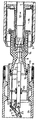
- the figure shows schematically in a longitudinal section a Interrupter unit of a high-voltage circuit breaker.
- the illustrated high voltage circuit breaker has two Arc contact pieces 1, 2, which face each other coaxially.
- the illustration shows a state during the Switching movement shortly before reaching the switch-off state.
- the Arc contact pieces 1, 2 are already separated and between them burns an arc 3.
- the first Arc contact piece 1 is in the direction of the arrow 12, the second arcing contact piece 2 moves in the direction of the arrow 13.
- the first arcing contact piece 1 is hollow and takes in the on state, the pin-shaped second arcing contact piece 2 on.
- the first arcing contact piece 1 is coupled to a contact tube 4, which is also the first drive element does not serve and the drive movement of one transfers illustrated energy storage.
- the first arcing contact 1 carries a multi-part Isolierstoffdüse 9, which in the on state, the second arcing contact piece 2 surrounds and during the turn-off the heated by the arc 3 extinguishing gas passes.
- First can through a channel 14 hot extinguishing gas in a boiler room 15 stream out of it at a suitable time, shortly after Current zero crossing of the alternating current to be switched through the same channel 14 flows back to the arc third to blow and reconsolidation of the switching path too accelerate.
- the free end of the insulating nozzle 9 is guided in a tube 10, which simultaneously forms a field electrode.
- a drive element 5 attached in the form of a rod made of PTFE.
- a ring 16 attached, with one end of the second drive element 5 is screwed.
- the second drive element 5 is the two-armed lever 11 is actuated.
- the rod 5 is pulled in the direction of arrow 17, whereby the lever 11 is pivoted clockwise. hereby is a pulling movement in the direction of arrow 13 on the second arc contact piece 2 transmitted.
- the second arcing contact piece 2 is by means of a Gleitcard arrangement 20 in the axial direction within the field electrode 10 led and contacted.
- the field electrode 10 is in turn in circumferential sliding contacts 21, 22 of the TreasurestromWallet institutions 8 led and contacted.
- the lever 11 of the reversing gear 6 is shown schematically Way pivoted about the stationary axis 23.
- the axis 23 may be fixed in the support tube 24, for example be that carries the Treasurestromutton réelle 8.
Landscapes
- Circuit Breakers (AREA)
- Arc-Extinguishing Devices That Are Switches (AREA)
Description
Die Erfindung bezieht sich auf einen Hochspannungs-Leistungsschalter mit einem ersten und einem zweiten, einander koaxial gegenüberstehenden Lichtbogenkontaktstück, zwischen denen bei einem Ausschaltvorgang gegebenenfalls ein Schaltlichtbogen brennt und die im Zuge eines Ausschaltvorganges durch einen gemeinsamen Antrieb in entgegengesetzten Richtungen antreibbar sind, wobei die Antriebsbewegung durch ein erstes Antriebselement auf das erste Lichtbogenkontaktstück und durch ein zweites Antriebselement mittels eines Umlenkgetriebes auf das zweite Lichtbogenkontaktstück übertragen wird und mit zwei die Lichtbogenkontaktstücke koaxial umgebenden Dauerstromkontaktstücken sowie mit einer Isolierstoffdüse, die mit dem ersten Lichtbogenkontaktstück fest verbunden ist und die der Beblasung des Schaltlichtbogens mit einem Löschgas dient.The invention relates to a high-voltage circuit breaker with a first and a second, coaxial with each other opposite arcing contact piece, between which at a switch-off optionally a switching arc burns and the in the course of a Ausschaltvorganges by a common drive drivable in opposite directions are, wherein the drive movement by a first drive element on the first arcing contact piece and through a second drive element by means of a deflection gear the second arcing contact piece is transmitted and with two persistent contact pieces coaxially surrounding the arcing contact pieces and with an insulating nozzle, with the first arcing contact piece is firmly connected and the the blowing of the switching arc with a quenching gas is used.
Ein derartiger Hochspannungs-Leistungsschalter ist beispielsweise in der französischen Patentanmeldung FR 2 491 675 beschrieben. Dort ist auch ausgeführt, daß durch die Aufteilung der Schaltbewegung auf zwei angetriebene Schaltkontaktstücke bei gleicher Antriebsenergie eine höhere Kontakttrennungsgeschwindigkeit erreicht wird, als wenn nur ein einziger Kontakt angetrieben wäre.Such a high-voltage circuit breaker is for example in French patent application FR 2 491 675. There is also stated that by the division the switching movement to two driven switching contact pieces at the same drive energy, a higher contact separation speed is achieved as if only a single contact would be driven.
Auch aus dem Fachartikel IEEE Transactions on Power Delivery, Vol. 8, No 3, July 1993, "DEVELOPMENT OF 550 kV 1-BREAK GCB (PART II)" ist ein Hochspannungs-Leistungsschalter mit zwei antreibbaren Schaltkontaktstücken bekannt, wobei die Antriebsbewegung auf eines der Schaltkontaktstücke direkt und auf das andere Schaltkontaktstück mittels eines Umlenkgetriebes übertragen wird. Also from the article IEEE Transactions on Power Delivery, Vol. 8, No 3, July 1993, "DEVELOPMENT OF 550 kV 1-BREAK GCB (PART II) "is a high-voltage circuit breaker with two drivable switching contact pieces known, the drive movement on one of the switching contact pieces directly and on the other switching contact piece by means of a deflection gear is transmitted.
Beim Stand der Technik ergibt sich, wie insbesondere aus der genannten französischen Patentanmeldung hervorgeht, daß die Antriebselemente zum Antrieb beider Schaltkontaktstücke sowie das Umlenkgetriebe regelmäßig viel Platz beanspruchen. Insbesondere bei der Konstruktion gemäß FR 2 491 675 wird deutlich, daß durch diese Konstruktion der Durchmesser der Unterbrechereinheit groß wird, so daß ein entsprechend großes Isolierstoffgehäuse zur Aufnahme der Unterbrechereinheit notwendig ist.In the prior art results, in particular from the French patent application states that the Drive elements for driving both switching contacts as well the reversing gear regularly take up much space. Especially in the design according to FR 2 491 675 it becomes clear that by this construction, the diameter of the interrupter unit becomes large, so that a correspondingly large insulating material necessary to accommodate the interrupter unit is.
Der vorliegenden Erfindung liegt die Aufgabe zugrunde, einen Hochspannungs-Leistungsschalter der eingangs genannten Art zu schaffen, der konstruktiv einfach aufgebaut und kostengünstig ist und eine möglichst geringe Gehäusegröße beansprucht.The present invention is based on the object, a High-voltage circuit breaker of the type mentioned above create, structurally simple and inexpensive is and claimed the smallest possible housing size.
Die Aufgabe wird erfindungsgemäß dadurch gelöst, dass das zweite Antriebselement an der Isolierstoffdüse befestigt und mittels dieser angetrieben ist und das Umlenkgetriebe einen ortsfest schwenkbar gelagerten zweiarmigen Hebel aufweist, an dem das zweite Antriebselement und das zweite Lichtbogenkontaktstück an Ankopplungspunkten angekoppelt sind.The object is achieved in that the second drive element attached to the insulating nozzle and is driven by this and the deflection gear a Fixed pivotally mounted two-armed lever, to the second drive element and the second arcing contact piece are coupled to coupling points.
Dadurch, dass das zweite Antriebselement an der Isolierstoffdüse befestigt ist, und die Isolierstoffdüse somit selbst die Antriebskraft auf das zweite Lichtbogenkontaktstück überträgt, kann das zweite Antriebselement relativ kurz gehalten werden. In der mechanischen Kette der die Antriebsbewegung übertragenden Elemente wird das erste Antriebselement von einem nicht im einzelnen dargestellten Kraftspeicher angetrieben und treibt seinerseits das erste Lichtbogenkontaktstück mit der Isolierstoffdüse an. Die Isolierstoffdüse treibt ihrerseits das zweite Antriebselement an, welches die Antriebsbewegung auf das hinter dem zweiten Lichtbogenkontaktstück angeordnete Umlenkgetriebe überträgt. Mittels des Umlenkgetriebes wird die Antriebsbewegung dann auf das zweite Lichtbogenkontaktstück übertragen. Characterized in that the second drive element on the insulating material is attached, and the insulating nozzle thus even the Transmitting drive power to the second arcing contact, the second drive element can be kept relatively short become. In the mechanical chain of the drive movement transferring elements becomes the first drive element of a not shown in detail power storage driven and in turn drives the first arcing contact with the insulating nozzle on. The Isolierstoffdüse drives in turn the second drive element, which the drive movement on the behind the second arcing contact piece arranged deflecting transmits. By means of the deflection gear the drive movement is then on the second arcing contact piece transfer.
Die Baugröße eines solchen Hochspannungs-Leistungsschalters ist genau gleich der Baugröße eines entsprechenden Schalters, bei dem nur eines der Lichtbogenkontaktstücke antreibbar ist und bei dem das zweite Antriebselement und das Umlenkgetriebe fehlen. Für beide Varianten des Schalters können somit gleiche Isolierstoffgehäuse, beispielsweise Porzellangehäuse verwendet werden.The size of such a high-voltage circuit breaker is exactly the size of a corresponding switch, in which only one of the arcing contact pieces can be driven and in which the second drive element and the deflection gear absence. For both variants of the switch can thus the same Isolierstoffgehäuse, for example, used porcelain housing become.
Da das zweite Antriebselement mit dem Lichtbogen bzw. mit heißem Löschgas in Kontakt kommen kann, sollte es aus einem lichtbogenresistenten Material, beispielsweise PTFE, hergestellt werden.Since the second drive element with the arc or with hot extinguishing gas may come into contact, it should come from a arc-resistant material, such as PTFE produced become.
Weiterhin kann vorteilhaft vorgesehen sein, dass der Abstand zwischen dem Ankopplungspunkt des zweiten Lichtbogenkontaktstückes und dem Ankopplungspunkt des zweiten Antriebselementes, insbesondere unter Belastung des Umlenkgetriebes, veränderbar ist.Furthermore, it can be advantageously provided that the distance between the coupling point of the second arcing contact piece and the coupling point of the second drive element, especially under load of the deflection, changeable is.
Eine Veränderung des Abstandes zwischen dem Ankopplungspunkt des zweiten Lichtbogenkontaktstückes und dem Ankopplungspunkt des zweiten Antriebselementes gestattet es, in einfacher Weise das Übersetzungsverhältnis des Umlenkgetriebes zu verändern. Insbesondere bei einer Veränderung des Abstandes während einer Übertragung einer Antriebsbewegung über das Umlenkgetriebe, d. h. unter Belastung des Umlenkgetriebes, kann das zweite Lichtbogenkontaktstück gezielt zusätzlich beschleunigt oder abgebremst werden.A change in the distance between the coupling point the second arcing contact piece and the coupling point the second drive element allows in a simple manner to change the transmission ratio of the reversing gear. Especially with a change in the distance during a transmission of a drive movement via the deflection gear, d. H. under load of the deflection, can the second arcing contact deliberately accelerated or slowed down.
Vorteilhafterweise kann weiter vorgesehen sein, dass ein Ankopplungspunkt gleitend in einer Kulisse geführt ist.Advantageously, it can further be provided that a coupling point slidably guided in a backdrop.
Eine kulissenartige Führung eines Ankopplungspunktes in einem Langloch stellt eine zuverlässige Verbindung mit dem Hebel dar. Durch das Langloch ist es in einfacher Weise möglich, den Abstand zwischen den Ankopplungspunkten von dem zweiten Antriebselement und dem Lichtbogenkontaktstück variabel zu ändern.A backdrop-like guidance of a docking point in one Long hole provides a reliable connection with the lever Through the slot it is possible in a simple manner, the distance between the coupling points of the second Drive element and the arcing contact piece variable too to change.
Vorteilhafterweise kann vorgesehen sein, dass das zweite Antriebselement radial innerhalb der Dauerstromkontaktstücke angeordnet ist.Advantageously, it can be provided that the second drive element radially within the persistent contact pieces is arranged.
Dadurch, dass das zweite Antriebselement radial innerhalb der Dauerstromkontaktstücke angeordnet ist, und nicht, wie beim Stand der Technik parallel zu dem ersten Antriebselement bzw. der Isolierstoffdüse radial außerhalb verläuft, wird die Baugröße der Unterbrechereinheit des erfindungsgemäßen Hochspannungs-Leistungsschalters in radialer Richtung kleingehalten. Dadurch, dass das zweite Antriebselement, beispielsweise in Form einer Antriebsstange, direkt an die Isolierstoffdüse und nicht an das erste Antriebselement angekoppelt ist, wird die notwendige Baulänge des zweiten Antriebselements und somit auch die beim Schaltvorgang zu beschleunigende Masse verringert.Characterized in that the second drive element radially within the Dauerstromkontaktstücke is arranged, and not, as in the State of the art parallel to the first drive element or the insulating nozzle runs radially outside, the size the interrupter unit of the high-voltage circuit breaker according to the invention kept small in the radial direction. Characterized in that the second drive element, for example in the form of a drive rod, directly to the insulating material nozzle and not coupled to the first drive element is, is the necessary length of the second drive element and thus also during the switching process to be accelerated Mass reduced.
Eine vorteilhafte Ausführungsform der Erfindung kann vorsehen, daß an das Umlenkgetriebe eine das zweite Lichtbogenkontaktstück umgebende Feldelektrode angekoppelt ist, die im Zuge einer Schaltbewegung gegensinnig zu dem zweiten Lichtbogenkontaktstück bewegbar ist.An advantageous embodiment of the invention can provide that at the reversing gear a the second arcing contact piece surrounding field electrode is coupled in the course a switching movement in opposite directions to the second arcing contact piece is movable.
Durch diese Konstruktion kann an dem Umlenkgetriebe ohne größeren zusätzlichen mechanischen Aufwand die Feldelektrode angekoppelt werden, die beim Ausschaltvorgang, wenn beide Lichtbogenkontaktstücke auseinandergezogen werden, vorgeschoben wird, um eine Vergleichmäßigung des elektrischen Feldes im Bereich der Trennstrecke zwischen den Lichtbogenkontaktstücken zu erreichen. Es kann vorgesehen sein, das Umlenkgetriebe so auszulegen, dass die Bewegung der Feldelektrode erst kurz vor dem Ende der Ausschaltbewegung beginnt.By this construction can be at the reversing gear without larger additional mechanical effort coupled to the field electrode be at the power off, if both Arc contact pieces are pulled apart, advanced is going to equalize the electric field in the area of the separation distance between the arcing contact pieces to reach. It can be provided, the deflection gear be interpreted that the movement of the field electrode begins shortly before the end of the switch-off movement.
Eine weitere vorteilhafte Ausgestaltung der Erfindung kann vorsehen, dass das zweite Lichtbogenkontaktstück und die Feldelektrode an den zweiarmigen Hebel angekoppelt sind.A further advantageous embodiment of the invention can Provide that the second arcing contact piece and the Field electrode are coupled to the two-armed lever.
Durch einen solchen Hebel ist das Umlenkgetriebe in einfachster und funktionssicherster Weise realisierbar. Dadurch, daß das Umlenkgetriebe von dem ersten Lichtbogenkontaktstück aus hinter dem zweiten Lichtbogenkontaktstück angeordnet ist, ist erreicht, daß beide Lichtbogenkontaktstücke beim Ausschaltvorgang, bei dem es auf eine extrem hohe Beschleunigung ankommt, mittels einer Zugbewegung angetrieben werden. Je nach der Ruhestellung des zweiarmigen Hebels kann ein passendes Beschleunigungsprofil des zweiten Lichtbogenkontaktstückes während der Ausschaltbewegung verwirklicht werden. Vorteilhaft geschieht die Ankopplung des zweiten Antriebselementes und des zweiten Lichtbogenkontaktstückes an den Hebel mittels Kulissenführungen, so daß die radiale Auslenkung dieser Elemente während der Schwenkbewegung des Hebels möglichst gering gehalten wird. Außerdem kann durch die Kulissenführungen ein Überhub des Antriebs kompensiert werden.By such a lever, the reversing gear is in the simplest and functionally safe manner feasible. As a result of that the reversing gear from the first arcing contact piece is arranged behind the second arcing contact piece is ensures that both arcing contact pieces at the turn-off, which requires extremely high acceleration be driven by a pulling movement. Depending on The rest position of the two-armed lever can be a suitable Acceleration profile of the second arcing contact piece be realized during the switch-off. Advantageous happens the coupling of the second drive element and the second arcing contact piece to the lever by means of Slotted guides, so that the radial deflection of these elements during the pivoting movement of the lever as low as possible is held. In addition, through the slide guides a Overlift of the drive can be compensated.
Im folgenden wird die Erfindung anhand eines Ausführungsbeispiels in einer Zeichnung gezeigt und nachfolgend beschrieben. In the following the invention with reference to an embodiment shown in a drawing and described below.
Dabei zeigt die Figur schematisch in einem Längsschnitt eine Unterbrechereinheit eines Hochspannungs-Leistungsschalters.The figure shows schematically in a longitudinal section a Interrupter unit of a high-voltage circuit breaker.
Der dargestellte Hochspannungs-Leistungsschalter weist zwei
Lichtbogenkontaktstücke 1, 2 auf, die einander koaxial gegenüberstehen.
Die Darstellung zeigt einen Zustand während der
Schaltbewegung kurz vor Erreichen des Ausschaltzustandes. Die
Lichtbogenkontaktstücke 1, 2 sind bereits voneinander getrennt
und zwischen ihnen brennt ein Lichtbogen 3. Das erste
Lichtbogenkontaktstück 1 wird in Richtung des Pfeils 12, das
zweite Lichtbogenkontaktstück 2 in Richtung des Pfeils 13 bewegt.
Das erste Lichtbogenkontaktstück 1 ist hohl ausgebildet
und nimmt im Einschaltzustand das stiftförmige zweite Lichtbogenkontaktstück
2 auf. Das erste Lichtbogenkontaktstück 1
ist an ein Kontaktrohr 4 angekoppelt, das auch als erstes Antriebselement
dient und die Antriebsbewegung von einem nicht
dargestellten Kraftspeicher überträgt.The illustrated high voltage circuit breaker has two
Arc contact pieces 1, 2, which face each other coaxially.
The illustration shows a state during the
Switching movement shortly before reaching the switch-off state. The
Arc contact pieces 1, 2 are already separated
and between them burns an arc 3. The first
Arc contact piece 1 is in the direction of the
Das erste Lichtbogenkontaktstück 1 trägt eine mehrteilige
Isolierstoffdüse 9, die im Einschaltzustand das zweite Lichtbogenkontaktstück
2 umgibt und während des Ausschaltvorganges
das durch den Lichtbogen 3 erhitzte Löschgas leitet. Zunächst
kann durch einen Kanal 14 heißes Löschgas in einen Heizraum
15 strömen, aus dem es dann zu geeigneter Zeit, kurz nach dem
Stromnulldurchgang des zu schaltenden Wechselstromes durch
denselben Kanal 14 wieder zurückströmt, um den Lichtbogen 3
zu beblasen und die Wiederverfestigung der Schaltstrecke zu
beschleunigen.The first arcing contact 1 carries a multi-part
Isolierstoffdüse 9, which in the on state, the second arcing contact piece
2 surrounds and during the turn-off
the heated by the arc 3 extinguishing gas passes. First
can through a channel 14 hot extinguishing gas in a
Das freie Ende der Isolierdüse 9 ist in einem Rohr 10 geführt,
das gleichzeitig eine Feldelektrode bildet.The free end of the
An dem freien Ende der Isolierstoffdüse 9 ist ein Antriebselement
5 in Form einer aus PTFE bestehenden Stange befestigt. At the free end of the
In dem Ausführungsbeispiel ist zunächst an der Düse ein Ring
16 befestigt, mit dem ein Ende des zweiten Antriebselementes
5 verschraubt ist. Durch das zweite Antriebselement 5 wird
der zweiarmige Hebel 11 betätigt. Während des Ausschaltvorganges
wird die Stange 5 in Richtung des Pfeils 17 gezogen,
wodurch der Hebel 11 im Uhrzeigersinn geschwenkt wird. Hierdurch
wird eine Zugbewegung in Richtung des Pfeils 13 auf das
zweite Lichtbogenkontaktstück 2 übertragen.In the embodiment, first at the nozzle is a
Gleichzeitig wird über eine ebenfalls an den Hebel 11 angekoppelte
Stange 18 die Feldelektrode 10 in Richtung des
Pfeils 19 bewegt.At the same time is coupled via a likewise coupled to the lever 11
Beim Einschaltvorgang finden die beschriebenen Vorgänge in umgekehrtem Richtungssinn statt.When switching on, the processes described in reversed direction sense instead.
Das zweite Lichtbogenkontaktstück 2 ist mittels einer Gleitkontaktführung
20 in axialer Richtung innerhalb der Feldelektrode
10 geführt und kontaktiert. Die Feldelektrode 10 ist
ihrerseits in umlaufenden Gleitkontakten 21, 22 des Dauerstromkontaktstücks
8 geführt und kontaktiert.The second arcing contact piece 2 is by means of a
Der Hebel 11 des Umlenkgetriebes 6 ist in schematisch dargestellter
Weise um die ortsfeste Achse 23 schwenkbar gelagert.
Die Achse 23 kann beispielsweise in dem Tragrohr 24 befestigt
sein, das das Dauerstromkontaktstück 8 trägt.The lever 11 of the
Claims (6)
- High-voltage circuit breaker having a first and a second arcing contact piece (1, 2), which are coaxially opposite one another, between which, during a disconnection procedure, a switching arc (3) may burn, and which, in the course of a disconnection procedure, can be driven in opposing directions by a common drive, the drive movement being transferred by a first drive element (4) to the first arcing contact piece (1) and by a second drive element (5), by means of a direction-changing drive (6), to the second arcing contact piece, and having two continuous current contact pieces (7, 8), which coaxially surround the arcing contact pieces (1, 2), and having a nozzle (9) made of dielectric material, which is permanently connected to the first arcing contact piece (1), and which is used to blow the switching arc (3) using a quenching gas, characterized in that the second drive element (5) is fixed to the nozzle (9) made of dielectric material, is driven by means of said nozzle (9) made of dielectric material, and the direction-changing drive has a two-armed lever (11), which is mounted such that it is fixed in position and such that it can pivot and to which the second drive element (5) and the second arcing contact piece (2) are coupled at coupling points.
- High-voltage circuit breaker according to Claim 1, characterized in that it is possible to vary the spacing between the coupling point of the second arcing contact piece (2) and the coupling point of the second drive element (5), in particular by loading the direction-changing drive.
- High-voltage circuit breaker according to either of Claims 1 and 2, characterized in that a coupling point is guided in a sliding manner in a guide.
- High-voltage circuit breaker according to one of Claims 1 to. 3, characterized in that the second drive element (5) is arranged radially within the continuous current contact pieces (7, 8).
- High-voltage circuit breaker according to one of Claims 1 to 4, characterized in that a field electrode (10), which surrounds the second arcing contact piece (2) and can be moved in the course of a switching movement in the opposite direction to the second arcing contact piece (2), is coupled to the direction-changing drive (6).
- High-voltage circuit breaker according to Claim 5, characterized in that the second arcing contact piece (2) and the field electrode (10) are coupled to the two-armed lever (11).
Priority Applications (1)
| Application Number | Priority Date | Filing Date | Title |
|---|---|---|---|
| DE29724842U DE29724842U1 (en) | 1996-05-24 | 1997-05-23 | HV circuit breaker with two drivable switch contact pieces - has drive element for second light arc contact piece attached to insulating nozzle for quenching gas and driven with it as well as being arranged radially inside permanent current contact pieces |
Applications Claiming Priority (2)
| Application Number | Priority Date | Filing Date | Title |
|---|---|---|---|
| DE19622460 | 1996-05-24 | ||
| DE19622460A DE19622460C2 (en) | 1996-05-24 | 1996-05-24 | High-voltage circuit breaker with two drivable switch contact pieces |
Publications (3)
| Publication Number | Publication Date |
|---|---|
| EP0809269A2 EP0809269A2 (en) | 1997-11-26 |
| EP0809269A3 EP0809269A3 (en) | 1998-11-25 |
| EP0809269B1 true EP0809269B1 (en) | 2005-04-27 |
Family
ID=7796144
Family Applications (1)
| Application Number | Title | Priority Date | Filing Date |
|---|---|---|---|
| EP97250161A Revoked EP0809269B1 (en) | 1996-05-24 | 1997-05-23 | High voltage circuit breaker with two driven switch contact pieces |
Country Status (2)
| Country | Link |
|---|---|
| EP (1) | EP0809269B1 (en) |
| DE (2) | DE19622460C2 (en) |
Cited By (2)
| Publication number | Priority date | Publication date | Assignee | Title |
|---|---|---|---|---|
| US7932476B2 (en) | 2006-12-06 | 2011-04-26 | Abb Technology Ag | Transmission for an electrical circuit breaker |
| CN101202175B (en) * | 2006-12-11 | 2013-01-02 | Abb技术有限公司 | Circuit breaker with a gear having a dead point |
Families Citing this family (35)
| Publication number | Priority date | Publication date | Assignee | Title |
|---|---|---|---|---|
| FR2774503B1 (en) * | 1998-02-02 | 2000-04-07 | Gec Alsthom T & D Sa | MEDIUM OR HIGH VOLTAGE CIRCUIT BREAKER HAVING A TRANSMISSION BELT CLOSED AROUND TWO PINIONS |
| FR2779566B1 (en) * | 1998-06-08 | 2000-06-30 | Alsthom Gec | DOUBLE MOTION HIGH OR MEDIUM VOLTAGE CIRCUIT BREAKER INCLUDING A TRANSLATION-GUIDED BLOWER NOZZLE |
| DE19858793A1 (en) * | 1998-12-18 | 2000-06-21 | Alstom Energietechnik Gmbh | Gas pressure switch |
| DE29901205U1 (en) * | 1999-01-15 | 1999-05-12 | Siemens AG, 80333 München | High-voltage circuit breakers, in particular compressed gas circuit breakers |
| DE19907838A1 (en) * | 1999-02-24 | 2000-08-31 | Alstom Energietechnik Gmbh | Gas pressure switch |
| DE19958645C5 (en) * | 1999-12-06 | 2011-05-26 | Abb Technology Ag | Hybrid circuit breaker |
| DE19963256C1 (en) * | 1999-12-17 | 2001-05-23 | Siemens Ag | HV load switch has drive for second movable contact supplied with release signal when first driven contact reaches given position |
| DE10003359C1 (en) * | 2000-01-21 | 2001-07-19 | Siemens Ag | High-voltage circuit breaker with two drivable arcing contact pieces and a boiler room |
| FR2817389B1 (en) * | 2000-11-30 | 2003-01-03 | Schneider Electric High Voltag | HIGH VOLTAGE ELECTRICAL CUTTING EQUIPMENT WITH DOUBLE MOVEMENT |
| FR2906642B1 (en) | 2006-09-29 | 2008-12-19 | Areva T & D Sa | CYLINDRICAL CAM ACTUATION OF THE CONTACTS OF A DOUBLE MOVEMENT CUTTING CHAMBER. |
| FR2906929B1 (en) * | 2006-10-09 | 2009-01-30 | Areva T & D Sa | ACTUATION BY CONTACTS OF A DOUBLE MOVEMENT CUT CHAMBER BY AN INSULATING TUBE |
| FR2906931B1 (en) * | 2006-10-09 | 2009-07-17 | Areva T & D Sa | CUTTING CHAMBER WITH CYLINDER FIELD DISTRIBUTION FOR HIGH VOLTAGE OR MEDIUM VOLTAGE CIRCUIT BREAKERS |
| FR2915310B1 (en) * | 2007-04-17 | 2009-07-10 | Areva T & D Sa | CIRCUIT BREAKER WITH DOUBLE MOVEMENT CHAMBER AND REVERSE STRUCTURE. |
| FR2949170B1 (en) * | 2009-08-14 | 2011-11-25 | Areva T & D Sas | BREAKER CHAMBER FOR A MEDIUM OR HIGH VOLTAGE CIRCUIT BREAKER WITH REDUCED MANEUVER POWER |
| FR2953639B1 (en) * | 2009-12-09 | 2012-01-13 | Areva T & D Sas | HIGH VOLTAGE CIRCUIT BREAKER WITH REMOVABLE SCREEN FOR IMPROVING THE GRADIENT OF FIELD |
| EP2343720A1 (en) * | 2010-01-12 | 2011-07-13 | ABB Technology AG | Gas-isolated high voltage switch |
| DE102011078483A1 (en) * | 2011-06-30 | 2013-01-03 | Siemens Aktiengesellschaft | Electrical switching device |
| DE102012205224A1 (en) * | 2012-03-30 | 2013-10-02 | Alstom Technology Ltd. | Air blast switch |
| FR2995131A1 (en) * | 2012-12-12 | 2014-03-07 | Alstom Technology Ltd | EXTERNAL ROOM CIRCUIT BREAKER |
| US20140175061A1 (en) | 2012-12-20 | 2014-06-26 | Abb Technology Ag | Electrical switching device with a triple motion contact arrangement |
| DE102013200918A1 (en) | 2013-01-22 | 2014-07-24 | Siemens Aktiengesellschaft | Switchgear arrangement |
| DE102013200913A1 (en) * | 2013-01-22 | 2014-07-24 | Siemens Aktiengesellschaft | switching arrangement |
| DE102013200914A1 (en) | 2013-01-22 | 2014-07-24 | Siemens Aktiengesellschaft | Switching method and switching device |
| FR3001329B1 (en) * | 2013-01-24 | 2015-02-27 | Alstom Technology Ltd | DOUBLE-MOVING CONTACTS ELECTRICAL EQUIPMENT COMPRISING A TWO-LEVER RETURN APPARATUS |
| WO2014121483A1 (en) * | 2013-02-07 | 2014-08-14 | 厦门华电开关有限公司 | Switch transmission mechanism and power switch |
| FR3008225B1 (en) * | 2013-07-08 | 2016-11-25 | Alstom Technology Ltd | REMOVABLE SCREEN BREAKER |
| DE102013217337A1 (en) | 2013-08-30 | 2015-03-05 | Siemens Aktiengesellschaft | High voltage circuit breaker |
| DE102014102929A1 (en) * | 2014-03-05 | 2015-09-10 | Abb Technology Ag | Gas damper for a high voltage switch |
| CN103839728A (en) * | 2014-03-10 | 2014-06-04 | 现代重工(中国)电气有限公司 | Tank-type breaker for gas insulated switchgear |
| JP2017050048A (en) * | 2015-08-31 | 2017-03-09 | 株式会社日立製作所 | Gas Circuit Breaker |
| EP3151261B1 (en) * | 2015-10-02 | 2019-06-12 | Siemens Aktiengesellschaft | Cam circuit-breaker for medium and high voltages |
| DE102019214432B4 (en) * | 2019-09-23 | 2024-02-08 | Siemens Energy Global GmbH & Co. KG | Assembly for a high-voltage circuit breaker and corresponding high-voltage circuit breaker |
| CN112635231B (en) * | 2020-10-21 | 2023-05-12 | 平高集团有限公司 | Double-acting arc extinguishing chamber of circuit breaker and circuit breaker using same |
| CN116130314B (en) * | 2023-03-08 | 2024-11-22 | 西安西电开关电气有限公司 | A bidirectional motion structure and method for shielding an arc extinguishing chamber |
| CN121011462B (en) * | 2025-10-27 | 2026-02-03 | 西安西电高压开关有限责任公司 | Double-acting arc extinguishing chamber, switching-on and switching-off method and circuit breaker |
Family Cites Families (5)
| Publication number | Priority date | Publication date | Assignee | Title |
|---|---|---|---|---|
| US3896282A (en) * | 1973-05-25 | 1975-07-22 | S & C Electric Co | High voltage circuit interrupting device |
| SE430446B (en) * | 1979-07-11 | 1983-11-14 | Asea Ab | ELECTRICAL SWITCH WITH GASFUL EXTENSION |
| FR2491675A1 (en) * | 1980-10-07 | 1982-04-09 | Alsthom Atlantique | Gas blast type high voltage circuit breaker - has operating piston moving contact ring axially into set of contacts held on hemispherical support |
| CH675175A5 (en) * | 1987-10-27 | 1990-08-31 | Bbc Brown Boveri & Cie | |
| DE4427163A1 (en) * | 1994-08-01 | 1996-02-08 | Abb Management Ag | Gas pressure switch |
-
1996
- 1996-05-24 DE DE19622460A patent/DE19622460C2/en not_active Expired - Fee Related
-
1997
- 1997-05-23 DE DE59712280T patent/DE59712280D1/en not_active Revoked
- 1997-05-23 EP EP97250161A patent/EP0809269B1/en not_active Revoked
Cited By (3)
| Publication number | Priority date | Publication date | Assignee | Title |
|---|---|---|---|---|
| US7932476B2 (en) | 2006-12-06 | 2011-04-26 | Abb Technology Ag | Transmission for an electrical circuit breaker |
| CN101202175B (en) * | 2006-12-11 | 2013-01-02 | Abb技术有限公司 | Circuit breaker with a gear having a dead point |
| US8415578B2 (en) | 2006-12-11 | 2013-04-09 | Abb Technology Ag | Circuit breaker with a gear having a dead point |
Also Published As
| Publication number | Publication date |
|---|---|
| DE19622460A1 (en) | 1997-11-27 |
| DE19622460C2 (en) | 1998-04-02 |
| EP0809269A3 (en) | 1998-11-25 |
| EP0809269A2 (en) | 1997-11-26 |
| DE59712280D1 (en) | 2005-06-02 |
Similar Documents
| Publication | Publication Date | Title |
|---|---|---|
| EP0809269B1 (en) | High voltage circuit breaker with two driven switch contact pieces | |
| EP2923370B1 (en) | Switching device arrangement | |
| DE2723552C2 (en) | Electric pressure gas switch | |
| EP0953199B1 (en) | High-voltage power switch with an axially displaceable field electrode | |
| EP0500550B1 (en) | Isolator switch for metal-clad, compressed-gas-insulated high-voltage switchgear | |
| DE102012211376A1 (en) | switching arrangement | |
| EP2923369B1 (en) | Switching method and switching device | |
| DE29709084U1 (en) | Gas pressure switch | |
| EP2728602B1 (en) | Electrical high voltage circuit breaker and method for opening same | |
| DE2319836C3 (en) | Circuit breaker | |
| EP0763840A2 (en) | Metal-clad gas insulated power switch | |
| EP1630841B1 (en) | Switching-chamber and high-power circuit-breaker | |
| WO1991015025A1 (en) | Gas-driven power switch with power-assisted piston | |
| DE102012205224A1 (en) | Air blast switch | |
| DE19702822C1 (en) | HV circuit breaker with field electrode | |
| DE29724842U1 (en) | HV circuit breaker with two drivable switch contact pieces - has drive element for second light arc contact piece attached to insulating nozzle for quenching gas and driven with it as well as being arranged radially inside permanent current contact pieces | |
| EP2718950B1 (en) | Switching device | |
| DE2320744C3 (en) | Plug-in device | |
| DE19730583B4 (en) | Air blast switch | |
| DE8119801U1 (en) | Contact system for compressed gas circuit breakers | |
| DE2703550C2 (en) | Electric switch | |
| EP3590123B1 (en) | Arrangement and method for switching high currents in high-voltage engineering | |
| DE3307401C2 (en) | ||
| DE10054554A1 (en) | Multi-phase HV load switch has offset contact operation of interrupters used for preventing overvoltages | |
| DE1590210A1 (en) | Electric switch |
Legal Events
| Date | Code | Title | Description |
|---|---|---|---|
| PUAI | Public reference made under article 153(3) epc to a published international application that has entered the european phase |
Free format text: ORIGINAL CODE: 0009012 |
|
| AK | Designated contracting states |
Kind code of ref document: A2 Designated state(s): CH DE FR GB LI |
|
| PUAL | Search report despatched |
Free format text: ORIGINAL CODE: 0009013 |
|
| AK | Designated contracting states |
Kind code of ref document: A3 Designated state(s): CH DE FR GB LI |
|
| 17P | Request for examination filed |
Effective date: 19981217 |
|
| GRAP | Despatch of communication of intention to grant a patent |
Free format text: ORIGINAL CODE: EPIDOSNIGR1 |
|
| GRAS | Grant fee paid |
Free format text: ORIGINAL CODE: EPIDOSNIGR3 |
|
| GRAA | (expected) grant |
Free format text: ORIGINAL CODE: 0009210 |
|
| AK | Designated contracting states |
Kind code of ref document: B1 Designated state(s): CH DE FR GB LI |
|
| PG25 | Lapsed in a contracting state [announced via postgrant information from national office to epo] |
Ref country code: GB Free format text: LAPSE BECAUSE OF FAILURE TO SUBMIT A TRANSLATION OF THE DESCRIPTION OR TO PAY THE FEE WITHIN THE PRESCRIBED TIME-LIMIT Effective date: 20050427 |
|
| REG | Reference to a national code |
Ref country code: GB Ref legal event code: FG4D Free format text: NOT ENGLISH |
|
| REG | Reference to a national code |
Ref country code: CH Ref legal event code: EP |
|
| REG | Reference to a national code |
Ref country code: CH Ref legal event code: NV Representative=s name: SIEMENS SCHWEIZ AG |
|
| REF | Corresponds to: |
Ref document number: 59712280 Country of ref document: DE Date of ref document: 20050602 Kind code of ref document: P |
|
| GBV | Gb: ep patent (uk) treated as always having been void in accordance with gb section 77(7)/1977 [no translation filed] |
Effective date: 20050427 |
|
| PLBI | Opposition filed |
Free format text: ORIGINAL CODE: 0009260 |
|
| PLAX | Notice of opposition and request to file observation + time limit sent |
Free format text: ORIGINAL CODE: EPIDOSNOBS2 |
|
| 26 | Opposition filed |
Opponent name: ABB SCHWEIZ AG Effective date: 20060126 |
|
| ET | Fr: translation filed | ||
| RDAF | Communication despatched that patent is revoked |
Free format text: ORIGINAL CODE: EPIDOSNREV1 |
|
| PGFP | Annual fee paid to national office [announced via postgrant information from national office to epo] |
Ref country code: DE Payment date: 20080721 Year of fee payment: 12 Ref country code: CH Payment date: 20080807 Year of fee payment: 12 |
|
| RDAG | Patent revoked |
Free format text: ORIGINAL CODE: 0009271 |
|
| STAA | Information on the status of an ep patent application or granted ep patent |
Free format text: STATUS: PATENT REVOKED |
|
| REG | Reference to a national code |
Ref country code: CH Ref legal event code: PL |
|
| 27W | Patent revoked |
Effective date: 20080725 |
|
| PGFP | Annual fee paid to national office [announced via postgrant information from national office to epo] |
Ref country code: FR Payment date: 20080516 Year of fee payment: 12 |