EP0809196B1 - Druckapparat mit der Möglichkeit, ein Zeichen mit einer eine Leerstelle aufweisenden Verzierung zu drucken - Google Patents
Druckapparat mit der Möglichkeit, ein Zeichen mit einer eine Leerstelle aufweisenden Verzierung zu drucken Download PDFInfo
- Publication number
- EP0809196B1 EP0809196B1 EP97108375A EP97108375A EP0809196B1 EP 0809196 B1 EP0809196 B1 EP 0809196B1 EP 97108375 A EP97108375 A EP 97108375A EP 97108375 A EP97108375 A EP 97108375A EP 0809196 B1 EP0809196 B1 EP 0809196B1
- Authority
- EP
- European Patent Office
- Prior art keywords
- character
- color
- embellishment
- embellished
- Prior art date
- Legal status (The legal status is an assumption and is not a legal conclusion. Google has not performed a legal analysis and makes no representation as to the accuracy of the status listed.)
- Expired - Lifetime
Links
Images


Classifications
-
- G—PHYSICS
- G06—COMPUTING OR CALCULATING; COUNTING
- G06F—ELECTRIC DIGITAL DATA PROCESSING
- G06F40/00—Handling natural language data
- G06F40/10—Text processing
- G06F40/103—Formatting, i.e. changing of presentation of documents
Definitions
- the present invention relates to a printing apparatus including a tape printing apparatus, a wordprocessor etc..
- the present invention relates to a printing apparatus which can print characters, each being embellished so as to have an outline portion and a blank portion within the outline portion, the printing apparatus being able to print the outline portion and the blank portion with different color, respectively.
- tape printing apparatuses which can print characters and the like with multi-color on print tapes.
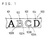
- characters 101, 102, 103, 104 can be printed on a print tape 100, with colors each of which is set to each character 101, 102, 103, 104.
- characters that are printed with multi-color there exist not only normal characters 101, 104 but also characters variously embellished such as characters 102, 103.
- the outline portions 102A, 103A are only printed with colors each of which is set to each character 102, 103.
- the outline portions 102A, 103A and the blank portions 102B, 103B can be respectively printed with different color, it can obtain clear contrast between the outline portions 102A, 103A and the blank portions 102B, 103B, based on that different color is used for the outline portions 102A, 103A and the blank portions 102B, 103B, respectively. Therefore, outward appearance of the embellished characters 102, 103 can be remarkably improved.
- a printing apparatus according to the preamble of claim 1 or claim 10 is known. It is capable of printing a character with two colors based on print data transmitted form a host computer.
- the printer prints, for example, a hollow character with its blank portion colored with a first color and its outline portion colored with a second color.
- the character input by the input means is selectively embellished in the first form that the character is embellished so as to have the outline portion and the blank portion. And further, the first print color and the second print color are set to the embellished character through the color set means. Thereafter, when the character is printed by the print means, the outline portion is printed with the first print color and the blank portion is printed with the second print color. Therefore, since the outline portion and blank portion in the character are printed with different color, respectively, outward appearance of the character is remarkably improved.
- the character input by the input means is selectively embellished in the first form that the character is embellished so as to have the outline portion and the blank portion.
- the first print color and the second print color are set to the embellished character through the color set means.
- the outline portion is printed with the first print color and the blank portion is printed with the second print color on the print tape. Therefore, since the outline portion and blank portion in the character are printed with different color, respectively, it can realize the tape printing apparatus in which outward appearance of the character is remarkably improved.
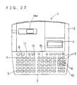
- the printing apparatus of the present invention is embodied as a tape printing apparatus ( hereinafter, abbreviated as "tape printer” ) 1 shown in Fig. 20.
- the tape printer 1 can print normal characters 101, 104 with normal embellishment and characters 102, 103 embellished so as to have blank portions 102B, 103B on a print tape 100.
- the tape printer 1 can print them so that outline portions 102A, 103A and the blank portions 102B, 102B are printed on the print tape 100 with different color, respectively.
- a keyboard 3 is arranged, and a thermal print mechanism PM is arranged in the main body 2 at the rear position of the keyboard 3.
- a liquid crystal display 4 At the right rear position of the key board 3, it is positioned a liquid crystal display 4 on which characters such as letters, numerals input from the keyboard 3 are displayed.
- keyboard 3 there are arranged various keys necessary for operation of the tape printer 1, as described hereinafter.
- character keys 5 to input various characters such as letters, numerals
- a range setting key 6 utilized when the range within which background pattern such as mesh pattern is added behind the characters is set
- a format setting key 7 to set the kind of frame added around the characters
- a print key 8 to conduct printing of the characters, etc.
- a right and left key 9 to move a cursor rightward and leftward on the liquid crystal display 4
- a return key 10 to conduct various procedures
- a ruled line key 11 to select the kind of background pattern
- a size key 12 to set the size of characters
- a font key 13 to set the font of characters such as Gothic
- an embellishing key 14 to set character embellishment such as the bag form, the bag form with shadow, stereo form, etc.
- cancel key 15 to cancel various procedures
- an up and down key 16 to move the cursor upward and downward on the liquid crystal display 4 and the other keys necessary for the tape printer 1.
- the tape cassette 110 which is detachably mounted in the thermal print mechanism PM, is constructed from a print tape part 120 in which the print tape 110 is wound and a ribbon part 121 in which a color ribbon 122 is wound. And when characters are printed on the print tape 100 by the thermal print mechanism PM, multi-color printing can be conducted by exchanging the ribbon part 121 with an other ribbon part 121 in which a color ribbon 122 with different color is wound. Concerning with multi-color printing, the construction to conduct the same multi-color printing is described in detail in United States Patent Application No. 08/617,058, Japanese Patent Application, laid-open number Hei 7-100,069, Japanese Patent Application, laid-open No. Hei 8-267,883. Therefore, detailed description of the multi-color printing is omitted.
- CGROM 21, ROM 30, input and output interface 23 are connected through bus line 24.
- CGROM 21 dot patterns corresponding to characters, numerals, etc. and dot pattern date for printing are stored.
- ROM 22 there are stored various programs such as main program shown in Fig. 2, range setting program shown in Fig. 3, format changing program within the range set by the range setting program shown in Fig. 4, printing program shown in Fig. 5, character embellishing program shown in Fig. 6, image displaying program shown in Fig. 8, and the other programs necessary for operation of the tape printer 1 and embellishing table 6 shown in Fig. 13 are stored in the ROM 22.
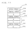
- the RAM 30 is memory area utilized when the CPU 20 conducts the above various programs. In the RAM 30, various memories are formed as shown in Fig. 22.
- text memory 31 text pointer storing area 32
- print buffer 33 constructed from image buffer
- display buffer 34 character positioning data storing area 35
- embellishing table storing area 36 data developing buffer 37
- embellishing buffer 38 and the other memory areas 39 are formed in the RAM 30.
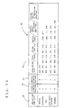
- the text memory 31 stores the format data of text (text data) and code data corresponding to the characters input from the keyboard 3. For instance, when the characters 101, 102, 103, 104 ( each corresponding to character A, B, C and D, respectively as shown in Fig. 1 ) are input through the character key 5 on the key board 3, and the character 101 ( character A ), the character 104 ( character D ) are set to the normal characters and further the character 102 (character B ), and the character 103 ( character C ) are set to the embellished characters with the blank portions 102B, 103B, there will be stored, as shown in Fig.
- the print buffer 33 To the print buffer 33, the data read out from the CGROM 21 based on the text memory 31 is transmitted and stored therein. And the thermal head 26 conducts dot printing according to the data stored in the print buffer 33. Further, to the display buffer 34, the data read out from the CGROM 21 based on the text memory 31 is transmitted and stored therein. The liquid crystal display 4 displays the characters thereon according to the data stored in the display buffer 34.
- the character positioning data storing area 35 is utilized as a memory to store the character positioning data made in the printing process in Fig. 5.
- the character positioning data 40 is constructed from code data 41 corresponding to each character, X position data 42 and Y position data 43 used for directing each character position, character width data 44 corresponding to each character width and format data 45 corresponding to various data concerning with each character.
- the format data 45 includes information for each character about whether embellishment is added to or not, and what print color is set to.
- the character positioning data 40 when the characters A, B, C and D ( corresponding to the characters 101, 102, 103, 104 in Fig. 1, respectively ) are input through the character key 5 on the keyboard 3.
- the numeral added to the left side of character positioning data 40 means the address number 46.
- the embellishing table storing area 36 is utilized as a memory to store the data of embellishing table 60 which is used in the character embellishing process in Fig. 6.
- the embellishing table 60 will be described according to Fig. 13.
- the embellishing table 60 is constructed from embellishment kind data 61, lateral increase fraction data 62, vertical increase fraction data 63 and embellishment data 64.
- the embellishment kind data 61 represents what kind of embellishment is added to the character.
- the dot pattern in normal form embellishment becomes the dot pattern shown in Fig. 15
- the dot pattern in emphasis form embellishment becomes the dot pattern shown in Fig. 16
- the dot pattern in bag form embellishment becomes the dot pattern shown in Fig. 17
- the dot pattern in bag form with shadow embellishment becomes the dot pattern shown in Fig. 18
- the dot pattern in stereo form embellishment becomes the dot pattern shown in Fig. 19.
- the lateral increase fraction data 62 is defined by dot number in lateral direction on embellishing data area, based on the data area of normal embellishment in Fig. 15.
- the vertical increase fraction data 63 is defined by dot number in vertical direction on embellishing data area.
- embellishment data 64 is utilized when the dot pattern in each embellishment form is prepared from the dot pattern of normal embellishment. Since preparation of the dot pattern in each embellishment form is conducted in the character embellishing process in Fig. 6, the detailed description thereof will be briefly given hereinafter.
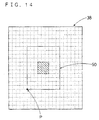
- the dot pattern in the bag form embellishment in Fig. 17 is prepared from the dot pattern in the normal embellishment in Fig. 15, at first, the dot pattern in Fig. 15 which is developed in the data developing buffer 37 is transmitted to the embellishing buffer 38 as shown in Fig. 14, based on the data "000" positioned at the head of embellishment data 64.
- the transmitted position of the dot pattern data becomes standard position when data transmitting is done.
- the dot pattern of the normal embellishment in Fig. 15 is transmitted to the embellishing buffer 38, so that the lower left corner point P of the data area 50 ( see Fig.
- the dot pattern of the normal embellishment in Fig. 15 is transmitted to the embellishing buffer 38, so that the lower left corner point P of the data area 50 ( see Fig. 14 ) is positioned at the position where the point P is shifted to the right direction by two dots.
- logical OR is obtained from the dot pattern shifted according to the above and the dot pattern already transmitted to the embellishing buffer 39.
- the dot pattern of the normal embellishment in Fig. 15 is transmitted to the embellishing buffer 38, so that the lower left corner point P of the data area 50 ( see Fig. 14 ) is positioned at the position where the point P is shifted to the upward direction by one dot.
- logical OR is obtained from the dot pattern shifted according to the above and the dot pattern already transmitted to the embellishing buffer 38. That is to say, in the embellishment data 64, the value at the second figure represents the moving amount of the dot pattern data to the upward direction when the data area 50 of the dot pattern of normal form is transmitted to the embellishing buffer 38.
- the dot pattern data of the normal embellishment in Fig. 15 is transmitted to the embellishing buffer 38.
- the dot pattern of the normal embellishment in Fig. 15 is transmitted to the embellishing buffer 38 after the dot pattern data is reversed, so that the lower left corner point P of the data area 50 ( see Fig. 14 ) is positioned at the position where the point P is shifted to both the right direction and the upward direction by one dot.
- logical AND is obtained from the dot pattern shifted according to the above and the dot pattern already transmitted to the embellishing buffer 38. That is to say, in the embellishment data 64, the value at the third figure represents that the dot pattern data of the normal embellishment is reversed and the logical AND is obtained, the dot pattern of the normal embellishment is transmitted to the embellishing buffer 38.
- the dot pattern of the normal embellishment in Fig. 15 becomes the dot pattern with the bag form embellishment in Fig. 17, after the logical AND is obtained on the embellishing buffer 38.
- the data area of the dot pattern with the bag form embellishment becomes wider by two dots in both the vertical direction and lateral direction than the data area 50 of the dot pattern with the normal embellishment.
- the data developing buffer 37 is utilized for developing the dot pattern data stored in the CGROM 21 or the dot pattern data for printing, before such data is transmitted to the print buffer 33 or the display buffer 34.
- the embellishing buffer 38 is utilized for preparing the dot pattern data with various embellishment from the dot pattern data with the normal embellishment.
- the keyboard 3, the display controller 25 and the thermal printing mechanism PM are connected to the input and output interface 30, the keyboard 3, the display controller 25 and the thermal printing mechanism PM are connected.
- the thermal printing mechanism PM the thermal head 26 is driven through the driver circuit 27 based on the printing program shown in Fig. 5 ( later mentioned ), thereby the print data stored in the print buffer 33 is printed on the print tape 100.
- the tape sending motor 28 is driven through the driver circuit 44, thereby tape sending operation of the print tape 100 is controlled.
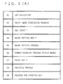
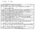
- Fig. 2 shows the flowchart of main program conducted in the tape printer 1, and the main program includes the range setting program to set the range for embellishment and the format changing program within the range set by the range setting program to set the print color for characters.
- step ( abbreviated as "S" hereinafter ) initialization is conducted over the tape printer 1.
- step (S2) the print image displaying process in Fig. 8 is done.
- the print image displaying process means the process to display the pint image, which is printed on the print tape 100, on the liquid crystal display 4. This process will be described later.
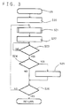
- the range setting process conducted in S5 is the process to set the range of characters each of which is embellished so as to be constructed from the outline portion and the blank portion. It will be described hereinafter the range setting process according to Fig. 3.
- the head position of the range and the last position thereof are set to the present cursor position displayed on the liquid crystal display 4 and both head and last positions are stored in the partial format storing area, which corresponds to each character, of the text memory 31.
- the print image displaying process is conducted, similarly in S2.
- the characters existing within the range defined by the head position and last position are reversely displayed on the liquid crystal display 4.
- S24 it is judged whether key input is done by the right and left key 9 on the keyboard 3. If judged key input is done by the right and left key 9 ( S24:YES ), both the head position and last position of the range are changed according to the cursor position movement based on key input from the right and left key 9, and both the head and last positions are stored in the partial format storing area 31D, thereby the embellishing range is set ( S25 ). Thereafter, procedure shifts to S26. For example, in case that the characters A, B, C and D are already input by the character key 5 and the cursor is moved form the character B to the character C in S24, the characters B and C are reversely displayed on the liquid crystal display 4 while the characters A and D are not reversed, as shown in Fig. 9.
- procedure directly shifts to S26.
- S26 it is judged whether key input is done by the return key 10. If judged that key input is done by the return key 10 ( S26:YES ), procedure shifts to S2 in Fig. 2. On the other hand, if judged that key input is not done by the return key 10 ( S26:NO ), procedure returns to S 21.
- procedure shifts to S6 in the main program in Fig. 2.
- S6 the format changing process within the range set according to the above is conducted.
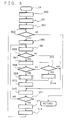
- the format changing process is the process that various formats (for example, size, embellishment, print color of each character ) are stored and set in the partial format storing area in the text memory 31. It will be described hereinafter the format changing process conducted in S6.
- the format setting information is displayed on the liquid crystal display 4.
- the format setting information which is presently set in the partial format storing area of the text memory 31, is partially displayed as shown in Fig. 10.
- the item “font” is used for setting the character font such as Gothic, etc., and in case of Fig. 10 four character fonts A - D are able to be set. Concretely, it is indicated in Fig. 10 that the character font A is set. Further, similarly to the above, the items “size”, “embellishment”, “character color 1" and “character color 2" are displayed on the liquid crystal display 4.
- the character size can be set by point numeral.
- the item “embellishment” two kinds of embellishment (one is the normal embellishment and the other is the embellishment in which the character is constructed from the outline portion and the blank portion ) can be set.
- the normal embellishment it can be set one of the normal embellishment and the emphasis embellishment.
- the embellishment with the outline portion and blank portion it can be set one of the bag form embellishment, the bag form embellishment with shadow and the stereo form embellishment.
- character color 1 color of the character with the normal embellishment and color of the outline portion of the character embellished with the outline portion and the blank portion can be set by numeral 1 - 3.
- the blank portion of the character embellished with the outline portion and the blank portion can be set by numeral 1 - 3.
- the numeral 1 - 3 is also used with the same meaning (that is, the same color) for the parameter COL in the printing process in Fig. 5, as mentioned later.
- S51 it is judged whether key input is done by any key on the keyboard 3. If judged that key input is done from the keyboard 3 ( S51:YES ), procedure shifts to S52. On the other hand, if judged that none of key input is done from the keyboard 3 ( S51:NO ), procedure repeats judgement in S51 until key input is done from the keyboard 3.
- S52 it is judged whether key input is done by the right and left key 9 on the keyboard 3. If judged that key input is done by the right and left key 9 ( S52:YES ), the cursor is moved on the liquid crystal display 4 according to key input from the right and left key 9 in S53, thereafter procedure shifts to S54 For instance, on the liquid crystal display 4 displaying the format setting information, if key input is done by the right key 9, the cursor is moved to the right direction. Thereby, The size "38P" is reversely displayed instead of the character font "A”. If judged that none of key input is done by the right and left key 9 (S52:NO), procedure directly shifts to S54.
- S54 it is judged whether key input is done by the up and down key 16. If judged that key input is done by the up and down key 16 ( S54:YES ), it is judged in S100 whether the cursor is positioned on the "character color 2". If judged that the cursor is not positioned on the "character color 2" ( S100:NO ), procedure shifts to S55. On the other hand, if judged that the cursor is positioned on the "character color 2" ( S100:YES ), it is further judged in S101 whether the normal embellishment or the emphasis embellishment is set as the character embellishment.
- procedure in S55 is conducted or if judged that key input is not done by the up and down key 16 ( S54:NO ), procedure directly shifts to S56.
- S56 it is judged whether key input is done by the return key 10 on the keyboard 3. If judged that key input is done by the return key 10 ( S56:YES ), procedure returns to S2 in the main program of Fig. 2. If judged that key input is not done by the return key 10 ( S56:NO ), procedure returns to S51.
- the character position-data 40 (see Fig. 12 ) is prepared according to various data stored in the text memory 31, thereafter the prepared character positioning data 40 is stored in the character positioning data storing area 35.
- the parameters CCT, COL are secured in the storing area 39 in the RAM 30 and the maximum value of print colors set in "character color 1" and “character color 2" is obtained based on the character positioning data 40, thereafter the obtained maximum value is substituted in the parameter CCT.
- value "0" is substituted in the parameter COL.
- value "0" in the parameter COL is defined to direct the print color "1”
- value "1" is defined to direct the print color "2”
- value "2" is defined to direct the print color "3".
- S66 it is judged whether, in the data read out from the character positioning data 40 in S65, the print color defined by value in the parameter COL is set. If judged that the print color defined by value in the parameter COL is set in the read out data ( S66:YES ), the print dot pattern corresponding to the code data 41 is read out in the data developing buffer 37 in S67. Further, in S68, it is judged whether value in the parameter COL corresponds to the "character color 1". If judged that the parameter COL corresponds to the "character color 1" ( S68:YES ), procedure shifts to S69 in which the character embellishing procedure is conducted.
- the character embellishing process is the process that the dot pattern with various embellishment is formed based on the dot pattern with the normal embellishment.
- the embellishment data 64 necessary for preparing the dot pattern is read out from the embellishing table 60, thereafter the embellishment data 64 is stored in the embellishment table storing area 37.
- the area for storing the pointer is secured in the storing area 39 and the pointer is set at the head position of the embellishment data 64 stored in the embellishment table storing area 37.
- the embellishment data 64 corresponding to the pointer is read out, and it is judged in S83 whether the embellishment data 64 is "FFF". If judged that the embellishment data 64 is not "FFF” ( S83:YES ) and the third figure of the embellishment data 64 is "0" ( S84:YES ), procedure shifts to S85.
- S85 based on the embellishment data 64, the print dot pattern in the data developing buffer 37 is transmitted to the embellishing buffer 38 and the logical OR is obtained from the print dot pattern transmitted and the dot pattern already transmitted to the embellishing buffer 38.
- the pointer is set to the next data in the embellishment data 64 and procedure returns to S82, thereafter, the above procedures are repeated.
- the embellishment data 64 is "FFF" ( S83:NO )
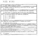
- This process is the process that the dot pattern of the blank portion formed within the outline portion is prepared, concerning with the characters having the blank portion therein such that the character embellishing form is set to "bag form embellishment", "bag form embellishment with shadow”, "stereo form embellishment”.
- the embellishment table 60 is searched based on the format data 45 set in the data of the character positioning data 40, which is read out in S65 in the printing process shown in Fig. 5, and not only the embellishment data 60 is read out but also the read out data 60 is stored in the embellishment data table storing area 36, thereafter the embellishing buffer 38 necessary for embellishing is secured.
- the pointer is secured in the storing area 39 and is set at the head position of the embellishment data 60 stored in the embellishment data table storing area 36.
- the embellishment data corresponding to the pointer is read out.
- S108 it is judged whether the embellishment form is the embellishment with the blank portion. This judgement is done based on whether the third figure of the embellishment data 64 is set to "1". Here, if the third figure is set to "1”, it concludes that the embellishment with the blank portion is set, and contrarily, if the third figure is not set to "1", it concludes that the embellishment with the blank portion is not set.
- the print dot pattern stored in the data developing buffer 37 is transmitted to the embellishing buffer 38 based on the embellishment data 64, and the logical OR is obtained from the transmitted dot pattern and the dot pattern already transmitted to the embellishing buffer 38. Thereafter, procedure shifts to S115.
- the print dot pattern obtained by reversing the dot pattern in the data developing buffer 37 based on the embellishment data 64 is transmitted to the embellishing buffer 38, and the logical AND is obtained from the transmitted dot pattern and the dot pattern already transmitted to the embellishing buffer 38. Thereafter, procedure shifts to S115.
- procedure If judged that the value of above equation is not equal to the value of parameter CEP (S71:NO), procedure returns to S65 and the above procedures are repeated. On the other hand, if judged that the value of equation is equal to the value of parameter CEP ( S71:YES ), procedure shifts to S73.
- S73 printing of characters is conducted. That is, the dot pattern data stored in the print buffer 33 is printed on the print tape 100 by the thermal printing mechanism PM. At this time, the dot pattern is printed through the ribbon part 121 in which the ribbon 122 having the color corresponding to the value "0" of the character parameter COL is installed.
- the print image displaying process means the process that the image to be printed on the print tape 100 is displayed on the liquid crystal display 4.
- the character positioning data 40 (see Fig. 12 ) is prepared based on the data stored in the text memory 31 and the prepared data 40 is stored in the character positioning data storing area 35.
- the character positioning data 40 prepared in S90 is converted to the data for displaying.
- the character parameters CSP, CEP and CC are secured and the address number 46 corresponding to the head position of the character positioning data 40 is set to the parameter CSP, the address number corresponding to the last position of the character positioning data 40 is set to the parameter CEP and value "0" is set to the parameter CC, thereby the parameters CSP, CEP and CC are initialized.
- the data corresponding to the address number defined by equation ( CSP+(CC ⁇ 10)) in the character positioning data 40 is read out.
- value "10" multiplied by the parameter CC in the equation means movement amount of the address by one stage in the character positioning data 40 in Fig. 12.
- the dot pattern is read out into the data developing buffer 37.
- the character embellishing procedure as same as the process in S69 ( see Fig. 5 ) is conducted.
- the process in S95 is different from the process in S69 at the point that the dot pattern data developed on the data developing buffer 37 is the dot pattern data for displaying in S95.
- the dot pattern with each embellishment prepared on the embellishing buffer 38 is transmitted to the display buffer 34 and the logical OR is obtained from the transmitted dot pattern and the dot pattern already transmitted thereto.
- the character parameter CC is increased by value "1".
- procedure according to the operated key is conducted. For example, if the character key 5 is depressed, characters such as letter, numeral, etc. are input.
- the print process is started.
- the character dot pattern of the character "A” is prepared and transmitted to the print buffer 33 ( S60 - S62, S63:YES, S64, S65, S66:YES, S67, S68:YES, S69, S75 ).
- S70, S71 S71:NO
- the same process is conducted about the character"B.
- "print color 1" is set to only the outline portion, therefore the dot pattern is prepared for only the outline portion and transmitted to the print buffer 33 ( S60 - S62, S63:Yes, S64, S65, S66:YES, S67, S68:YES, S69, S75 ).
- the print dot pattern is prepared for only the outline portion to which "print color 1" is set and transmitted to the print buffer 33 ( S60- S62, S63:YES, S64, S65, S66:YES, S67, S68:YES, S69, S75 ).
- the print dot pattern is prepared for only the outline portion to which "print color 1" is set, on the other hand, the print dot pattern is not prepared for the blank portion to which "print color 2" is set ( S66 ). Further, though the same process is conducted for the character "D".
- the print dot pattern is prepared for the character "D” and is transmitted to the print buffer 33 ( S60 - S62, S63:YES, S64, S65, S66:YES, S67, S68:YES, S69, S75 ).
- the tape printer 1 when one kind of the embellishment with the blank portion such as "bag form”, “bag form with shadow”, or “stereo form” is set to the characters input though the character key 5 on the keyboard 3 ( S9, S55 ) and the numeral corresponding to "print color 1" and “print color 2" is set to the characters ( S55 ), and further the characters are printed with multi-color on the print tape 100 though the thermal printing mechanism PM ( S73 ), the outline portions of the characters to which the embellishment with the blank portion is set are printed with "print color 1" and the blank portions of the thus embellished characters are printed with "print color 2". Therefore, the outline portion and the blank portion in the character can be printed with different color, respectively. As a result, the outward appearance of the embellished characters can be remarkably improved.
- the tape printer 1 so as to be able to set a shadow print mode in which only the shadow portion of the bag form is printed and a lateral stripe print mode in which the character is represented by the lateral stripe and is printed.
- it can print the character with two colors ( “print color 1” and “print color 2" ) by setting "print color 2" to the white portion except for the shadow portion or the lateral stripe portion, similar to the cases of the above “bag form", "bag form with shadow” and "stereo form”.
Landscapes
- Engineering & Computer Science (AREA)
- Theoretical Computer Science (AREA)
- General Physics & Mathematics (AREA)
- Artificial Intelligence (AREA)
- Computational Linguistics (AREA)
- General Health & Medical Sciences (AREA)
- Physics & Mathematics (AREA)
- General Engineering & Computer Science (AREA)
- Health & Medical Sciences (AREA)
- Audiology, Speech & Language Pathology (AREA)
- Record Information Processing For Printing (AREA)
- Controls And Circuits For Display Device (AREA)
- Printers Characterized By Their Purpose (AREA)
- Dot-Matrix Printers And Others (AREA)
- Color, Gradation (AREA)
- Document Processing Apparatus (AREA)
Claims (10)
- Druckgerät mit einem Eingabemittel (3, 5) zum Eingeben eines Zeichens (101, 102, 103, 104), einem Verzierungsmittel zum selektiven Verzieren der durch das Eingabemittel eingegebenen Zeichen in einer ersten Form so, daß das Zeichen so verziert ist, daß es einen Umrißabschnitt (102A, 103A) und einen leeren Abschnitt (102B, 103B) aufweist, oder in einer zweiten Form so, daß das Zeichen normal so verziert ist, daß es keinen leeren Abschnitt aufweist, einem Farbeinstellmittel zum Einstellen einer ersten Druckfarbe für den Umrißabschnitt und einer zweiten Druckfarbe für den leeren Abschnitt, der in der ersten Form existieren würde, und einem Druckmittel (PM) zum Drucken des verzierten Zeichens (102, 103) so, daß der Umrißabschnitt mit der ersten Druckfarbe gedruckt wird und der resultierende leere Abschnitt mit der zweiten Druckfarbe gedruckt wird;
gekennzeichnet durchein erstes Farbbeurteilungsmittel (20, S102) zum Urteilen ob sowohl die erste Druckfarbe als auch die zweite Druckfarbe gegenseitig auf die gleich Farbe eingestellt sind; ein Verhinderungsmittel (20, S102, S103) zum Verhindern des Einstellens der zweiten Druckfarbe für den leeren Abschnitt des verzierten Zeichens, der in der ersten Form existieren würde, wenn von dem ersten Farbbeurteilungsmittel geurteilt wird, daß sowohl die erste Druckfarbe als auch die zweite Druckfarbe gegenseitig auf die gleiche Farbe eingestellt sind; undein Drucksteuermittel (20) zum Steuern des Druckmittels zum Drucken mit der ersten Druckfarbe entweder des Umrißabschnittes des Zeichens in der ersten Form oder des ganzen Zeichens in der zweiten Form während einer ersten Drucktätigkeit und Drucken mit der zweiten Druckfarbe des leeren Abschnittes des Zeichens, der in der ersten Form existieren würde, während einer zweiten Drucktätigkeit auf die erste Drucktätigkeit folgend, wenn von dem ersten Farbbeurteilungsmittel geurteilt wird, daß sowohl die erste Druckfarbe als auch die zweite Druckfarbe nicht gegenseitig auf die gleiche Farbe eingestellt sind. - Druckgerät nach Ansprüche 1,
weiter mit einem Verzierungsbeurteilungsmittel (20, S72) zum Urteilen, ob das verzierte Zeichen in der ersten Form oder in der zweiten Form vorliegt. - Druckgerät nach Anspruch 2,bei dem das Verhinderungsmittel (20, S102, S103), das Einstellen der zweiten Druckfarbe für den leeren Abschnitt verhindert, wenn von dem Verzierungsbeurteilungsmittel geurteilt wird, daß das Zeichen in der ersten Form vorliegt, undbei dem das Druckmittel (PM) bevorzugt dann nur den Umrißabschnitt des verzierten Zeichens mit der ersten Druckfarbe druckt.
- Druckgerät nach Anspruch 2,bei dem das Verhinderungsmittel verhindert, daß die zweite Druckfarbe für das normal verzierte Zeichen eingestellt wird, wenn von dem Verzierungsbeurteilungsmittel geurteilt wird, daß das verzierte Zeichen in der zweiten Form vorliegt, undbei dem das Druckmittel (PM) bevorzugt das ganze verzierte Zeichen mit der ersten Druckfarbe druckt.
- Druckgerät nach einem der Ansprüche 1 bis 4,
bei dem das Druckmittel (PM) ein Punktmustererzeugungsmittel (21) zum Erzeugen eines Punktmusters des verzierten Zeichens aufweist. - Druckgerät nach Anspruch 5,
weiter mit einem zweiten Farbbeurteilungsmittel (20, S68) zum Urteilen, ob die erste Druckfarbe für das verzierte Zeichen eingestellt ist. - Druckgerät nach Anspruch 5 oder 6,
bei dem das Punktmustererzeugungsmittel (21) das Punktmuster entsprechend einem Teil des verzierten Zeichens erzeugt, für den die erste Druckfarbe eingestellt ist, und das Druckmittel (PM) den Teil mit der ersten Druckfarbe auf der Grundlage des erzeugten Punktmusters druckt, und bei dem das Druckmittel (PM) bevorzugt den Umrißabschnitt mit der ersten Druckfarbe in dem Fall des verzierten Zeichens mit dem leeren Abschnitt druckt und das ganze Zeichen in dem Fall des normal verzierten Zeichens ohne den leeren Abschnitt druckt. - Druckgerät nach Anspruch 5 oder 6,bei dem das Punktmustererzeugungsmittel (21) das Punktmuster entsprechend dem leeren Abschnitt erzeugt, wenn von dem zweiten Farbbeurteilungsmittel (20) geurteilt wird, daß die erste Druckfarbe nicht für das verzierte Zeichen eingestellt ist, und von dem Verzierungsbeurteilungsmittel (20) geurteilt wird, daß das verzierte Zeichen in der ersten Form vorliegt, undbei dem das Druckmittel (PM) bevorzugt den leeren Abschnitt mit der zweiten Druckfarbe auf der Grundlage des erzeugten Punktmusters druckt.
- Druckgerät nach einem der Ansprüche 1 bis 8,
bei dem die erste Form mindestens eine Taschenformverzierung, eine Taschenformverzierung mit Schatten und eine Stereoformverzierung aufweist und/oder die zweite Form mindesten eine Normalformverzierung und eine Verstärkungsformverzierung aufweist. - Banddruckgerät zum Erzeugen eines Druckbandes, auf das ein Zeichen gedruckt wird, mit einem Eingabemittel (3, 59) zum Eingeben eines Zeichens (101, 102, 103, 104), einem Verzierungsmittel zum selektiven Verzieren des durch das Eingabemittel eingegebenen Zeichens in einer ersten Form so, daß das Zeichen (102, 103) so verziert ist, daß es einen Umrißabschnitt (102A, 103A) und einen leeren Abschnitt (102B, 103B) aufweist, und in einer zweiten Form so, daß das Zeichen (101, 104) normal so verziert ist, daß es den leeren Abschnitt nicht aufweist, einem Farbeinstellmittel zum Einstellen einer ersten Druckfarbe für den Umrißabschnitt und einer zweiten Druckfarbe für den leeren Abschnitt des Zeichens, der in der ersten Form existieren würde, und einem Thermodruckmechanismus (PM) zum thermischen Drucken des verzierten Zeichens (102, 103) so, daß der Umrißabschnitt mit der ersten Druckfarbe gedruckt wird und der resultierende leere Abschnitt mit der zweiten Druckfarbe gedruckt wird;
gekennzeichnet durch:ein erstes Farbbeurteilungsmittel (20, S102) zum Urteilen, ob sowohl die erste Druckfarbe als auch die zweite Druckfarbe gegenseitig auf die gleich Farbe eingestellt sind;ein Verhinderungsmittel (20, S102, S103) zum Verhindern des Einstellens der zweiten Druckfarbe für den leeren Abschnitt des verzierten Zeichens, der in der ersten Form existieren würde, wenn von dem ersten Farbbeurteilungsmittel geurteilt wird, daß sowohl die erste Druckfarbe als auch die zweite Druckfarbe gegenseitig auf die gleiche Farbe eingestellt sind; undein Drucksteuermittel (20) zum Steuern des Thermodruckmechanismus (PM) zum Drucken mit der ersten Druckfarbe entweder des Umrißabschnittes des Zeichens in der ersten Form oder des gesamten Zeichens in der zweiten Form und Drucken mit der zweiten Druckfarbe des leeren Abschnittes des Zeichens, der in der ersten Form existieren würde, wenn von dem ersten Farbbeurteilungsmittel geurteilt wird, daß sowohl die erste Druckfarbe als auch die zweite Druckfarbe nicht gegenseitig auf die gleiche Farbe eingestellt sind.
Applications Claiming Priority (3)
| Application Number | Priority Date | Filing Date | Title |
|---|---|---|---|
| JP8129934A JPH09314909A (ja) | 1996-05-24 | 1996-05-24 | 印刷装置 |
| JP12993496 | 1996-05-24 | ||
| JP129934/96 | 1996-05-24 |
Publications (2)
| Publication Number | Publication Date |
|---|---|
| EP0809196A1 EP0809196A1 (de) | 1997-11-26 |
| EP0809196B1 true EP0809196B1 (de) | 1999-11-17 |
Family
ID=15022046
Family Applications (1)
| Application Number | Title | Priority Date | Filing Date |
|---|---|---|---|
| EP97108375A Expired - Lifetime EP0809196B1 (de) | 1996-05-24 | 1997-05-23 | Druckapparat mit der Möglichkeit, ein Zeichen mit einer eine Leerstelle aufweisenden Verzierung zu drucken |
Country Status (4)
| Country | Link |
|---|---|
| US (1) | US5855440A (de) |
| EP (1) | EP0809196B1 (de) |
| JP (1) | JPH09314909A (de) |
| DE (1) | DE69700799T2 (de) |
Families Citing this family (2)
| Publication number | Priority date | Publication date | Assignee | Title |
|---|---|---|---|---|
| US7110147B1 (en) * | 1999-09-09 | 2006-09-19 | Seiko Epson Corporation | Image processing method and apparatus |
| US20060132871A1 (en) * | 2004-12-20 | 2006-06-22 | Beretta Giordano B | System and method for determining an image frame color for an image frame |
Family Cites Families (5)
| Publication number | Priority date | Publication date | Assignee | Title |
|---|---|---|---|---|
| DE69126590T2 (de) * | 1990-09-28 | 1997-10-02 | Fujitsu Ltd | Zeilenwärmedrucker |
| JP3006098B2 (ja) * | 1991-01-21 | 2000-02-07 | ブラザー工業株式会社 | 印字データ処理装置 |
| US5428728A (en) * | 1991-09-30 | 1995-06-27 | Destiny Technology Corporation | Method and apparatus for outline font character generation in dot matrix devices |
| US5374131A (en) * | 1992-06-01 | 1994-12-20 | Brother Kogyo Kabushiki Kaisha | Printer capable of spacing characters within frame |
| US5636926A (en) * | 1993-09-06 | 1997-06-10 | Brother Kogyo Kabushiki Kaisha | Tape-shaped label producing device |
-
1996
- 1996-05-24 JP JP8129934A patent/JPH09314909A/ja active Pending
-
1997
- 1997-05-22 US US08/861,629 patent/US5855440A/en not_active Expired - Lifetime
- 1997-05-23 EP EP97108375A patent/EP0809196B1/de not_active Expired - Lifetime
- 1997-05-23 DE DE69700799T patent/DE69700799T2/de not_active Expired - Fee Related
Also Published As
| Publication number | Publication date |
|---|---|
| US5855440A (en) | 1999-01-05 |
| JPH09314909A (ja) | 1997-12-09 |
| EP0809196A1 (de) | 1997-11-26 |
| DE69700799T2 (de) | 2000-04-27 |
| DE69700799D1 (de) | 1999-12-23 |
Similar Documents
| Publication | Publication Date | Title |
|---|---|---|
| JPH05305730A (ja) | テープ印字装置 | |
| US5496119A (en) | Tape printer having a display | |
| US6666593B2 (en) | Tape printing apparatus and image forming method and label producing method for the tape printing apparatus | |
| US6062750A (en) | Printer capable of printing a background in addition to text on a tape along with a decorating feature to extend the border of the printed tape | |
| US6567088B2 (en) | Image processing device | |
| EP0650841B1 (de) | Druckgerät | |
| EP0809196B1 (de) | Druckapparat mit der Möglichkeit, ein Zeichen mit einer eine Leerstelle aufweisenden Verzierung zu drucken | |
| JP3514056B2 (ja) | 画像作成装置 | |
| US6646649B1 (en) | Image display device, electronic apparatus having same, and image display method | |
| JPH07242023A (ja) | テープ印刷装置 | |
| US5579041A (en) | Printing device bordering function and a method thereof | |
| TW200530948A (en) | Device and method for producing bracket image, device and method for producing outer frame image, and recording medium | |
| JP3118999B2 (ja) | スケール印刷装置 | |
| JPH0872321A (ja) | テープ状ラベル作成装置 | |
| EP0660248B1 (de) | Textverarbeitungsgerät | |
| JP3050469B2 (ja) | テープ印字装置 | |
| JP2803509B2 (ja) | テープ印字装置 | |
| JP6432500B2 (ja) | 表示装置、及び、印刷装置 | |
| JPH0776146A (ja) | テープ印字装置 | |
| JP3752700B2 (ja) | バーコード印字方法 | |
| JP3347353B2 (ja) | 印刷装置並びに出力方法及び装置 | |
| JPH0781149A (ja) | ラベル作成用プリンタ | |
| JPH0781150A (ja) | ラベル作成用プリンタ | |
| JP3632294B2 (ja) | バーコード出力装置 | |
| JP3358614B2 (ja) | テープカートリッジ、テープ印刷方法、テープ印刷装置並びにラベル作成方法 |
Legal Events
| Date | Code | Title | Description |
|---|---|---|---|
| PUAI | Public reference made under article 153(3) epc to a published international application that has entered the european phase |
Free format text: ORIGINAL CODE: 0009012 |
|
| AK | Designated contracting states |
Kind code of ref document: A1 Designated state(s): BE DE FR GB |
|
| 17P | Request for examination filed |
Effective date: 19980504 |
|
| 17Q | First examination report despatched |
Effective date: 19980622 |
|
| GRAG | Despatch of communication of intention to grant |
Free format text: ORIGINAL CODE: EPIDOS AGRA |
|
| GRAG | Despatch of communication of intention to grant |
Free format text: ORIGINAL CODE: EPIDOS AGRA |
|
| GRAH | Despatch of communication of intention to grant a patent |
Free format text: ORIGINAL CODE: EPIDOS IGRA |
|
| GRAH | Despatch of communication of intention to grant a patent |
Free format text: ORIGINAL CODE: EPIDOS IGRA |
|
| GRAA | (expected) grant |
Free format text: ORIGINAL CODE: 0009210 |
|
| AK | Designated contracting states |
Kind code of ref document: B1 Designated state(s): BE DE FR GB |
|
| REF | Corresponds to: |
Ref document number: 69700799 Country of ref document: DE Date of ref document: 19991223 |
|
| ET | Fr: translation filed | ||
| PLBE | No opposition filed within time limit |
Free format text: ORIGINAL CODE: 0009261 |
|
| STAA | Information on the status of an ep patent application or granted ep patent |
Free format text: STATUS: NO OPPOSITION FILED WITHIN TIME LIMIT |
|
| 26N | No opposition filed | ||
| REG | Reference to a national code |
Ref country code: GB Ref legal event code: IF02 |
|
| PGFP | Annual fee paid to national office [announced via postgrant information from national office to epo] |
Ref country code: FR Payment date: 20090507 Year of fee payment: 13 Ref country code: DE Payment date: 20090529 Year of fee payment: 13 |
|
| PGFP | Annual fee paid to national office [announced via postgrant information from national office to epo] |
Ref country code: BE Payment date: 20090619 Year of fee payment: 13 |
|
| PGFP | Annual fee paid to national office [announced via postgrant information from national office to epo] |
Ref country code: GB Payment date: 20090407 Year of fee payment: 13 |
|
| BERE | Be: lapsed |
Owner name: *BROTHER KOGYO K.K. Effective date: 20100531 |
|
| GBPC | Gb: european patent ceased through non-payment of renewal fee |
Effective date: 20100523 |
|
| REG | Reference to a national code |
Ref country code: FR Ref legal event code: ST Effective date: 20110131 |
|
| PG25 | Lapsed in a contracting state [announced via postgrant information from national office to epo] |
Ref country code: BE Free format text: LAPSE BECAUSE OF NON-PAYMENT OF DUE FEES Effective date: 20100531 |
|
| PG25 | Lapsed in a contracting state [announced via postgrant information from national office to epo] |
Ref country code: DE Free format text: LAPSE BECAUSE OF NON-PAYMENT OF DUE FEES Effective date: 20101201 |
|
| PG25 | Lapsed in a contracting state [announced via postgrant information from national office to epo] |
Ref country code: FR Free format text: LAPSE BECAUSE OF NON-PAYMENT OF DUE FEES Effective date: 20100531 |
|
| PG25 | Lapsed in a contracting state [announced via postgrant information from national office to epo] |
Ref country code: GB Free format text: LAPSE BECAUSE OF NON-PAYMENT OF DUE FEES Effective date: 20100523 |