EP0809187A1 - Erweiterte Adressierung für mehrere Geräte von einem einzelnen parallelen Ein-/Ausgabetor - Google Patents
Erweiterte Adressierung für mehrere Geräte von einem einzelnen parallelen Ein-/Ausgabetor Download PDFInfo
- Publication number
- EP0809187A1 EP0809187A1 EP96116872A EP96116872A EP0809187A1 EP 0809187 A1 EP0809187 A1 EP 0809187A1 EP 96116872 A EP96116872 A EP 96116872A EP 96116872 A EP96116872 A EP 96116872A EP 0809187 A1 EP0809187 A1 EP 0809187A1
- Authority
- EP
- European Patent Office
- Prior art keywords
- epa
- command
- port
- address
- host computer
- Prior art date
- Legal status (The legal status is an assumption and is not a legal conclusion. Google has not performed a legal analysis and makes no representation as to the accuracy of the status listed.)
- Granted
Links
Images


Classifications
-
- G—PHYSICS
- G06—COMPUTING OR CALCULATING; COUNTING
- G06F—ELECTRIC DIGITAL DATA PROCESSING
- G06F12/00—Accessing, addressing or allocating within memory systems or architectures
- G06F12/02—Addressing or allocation; Relocation
- G06F12/06—Addressing a physical block of locations, e.g. base addressing, module addressing, memory dedication
- G06F12/0646—Configuration or reconfiguration
- G06F12/0653—Configuration or reconfiguration with centralised address assignment
- G06F12/0661—Configuration or reconfiguration with centralised address assignment and decentralised selection
-
- G—PHYSICS
- G06—COMPUTING OR CALCULATING; COUNTING
- G06F—ELECTRIC DIGITAL DATA PROCESSING
- G06F13/00—Interconnection of, or transfer of information or other signals between, memories, input/output devices or central processing units
- G06F13/38—Information transfer, e.g. on bus
- G06F13/40—Bus structure
- G06F13/4004—Coupling between buses
- G06F13/4022—Coupling between buses using switching circuits, e.g. switching matrix, connection or expansion network
Definitions
- This invention is communication protocol between a host computer and one or more peripheral units.
- Personal desktop computer parallel interface add-ons are becoming more numerous and useful. However, with the present parallel port, the user must keep connecting one and disconnecting another. Some of these add-ons provide a pass-through port connection for connecting a printer. Such a configuration can be seen in figure 2. Typically, a second add-on may not be connected to the pass-through port. Such daisy-chain may be possible, however, it may not always work.
- the parallel port on a personal computer was not designed for daisy-chaining.
- a method for logically connecting a host computer to more than one device over a parallel port assigns a unique address to each Extended Port Addressing (EPA) device on the parallel port.
- EPA Extended Port Addressing
- Each EPA device monitors the parallel port for the assign address command.
- the EPA device acknowledges to the host computer successful receipt of the assign address command.
- the EPA device must wait for the host computer to complete the assign address command. Assuming the host completes the command, the EPA device stores the unique address and enables the logical connection between the host computer and the downstream devices.
- the host computer After all the EPA devices have been assigned unique addresses, the host computer must issue an enable command to the EPA device before the host can communicate with the device. Again, the EPA device monitors the parallel port for the enable command. Upon detecting the enable command, first the EPA device verifies that its unique address is the same as the address in the enable command. Assuming the addresses match, the EPA device disables the logical connection between the host computer and the down-stream devices and acknowledges to the host computer successful receipt of the enable command.
- the host computer will send a termination signal when it has finished communicating with the device.
- the EPA device breaks the logical connection between the host computer and the EPA device and creates a logical connection between the host computer and the downstream devices.
- the exact termination signal depends on whether the enable command was a "select address" or "lock address.”
- FIG. 1 shows a typical layout using T-boxes in accordance with the present invention.
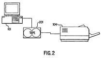
- FIG. 2 shows a typical layout using EPA compatible devices.
- FIG. 3 shows a layout that includes nested networks.
- FIG. 4 is a block diagram of a T-box device.
- FIG. 5 is a state diagram for the T-Box device.
- FIG. 6 is a timing diagram showing the events of the EPA negations process.
- FIG. 7 is a state diagram for the host.
- the present invention is not limited to a specific embodiment illustrated herein.
- the present invention Extended Port Addressing (EPA) is a physical link layer communication protocol for enumeration of more than one device attached to the same parallel port on a desktop personal computer.
- EPA automatically determines individual devices as they are added or removed from the parallel port.
- EPA also allows time sharing of device drivers to a particular device without any one device driver locking the logical port.
- EPA extends plug ' n ' play characteristics by determining if other devices share the same parallel port when attached to a T-box EPA device.
- Host computer 101 is connected to tape drive 102, scanner 103, and printer 104 through host's 101 printer parallel port.
- Each device (tape 102, scanner 103, and printer 104) is designed to independently connect to a standard parallel port on a personal computer.
- T-box 105 and 106 the parallel port of host 101 may be physically connected to all three devices simultaneously.
- T-box 105 connects host 101 to tape 102 and a second T-box 106.
- Tape 102 is connected to the Extended Port Address (EPA) port of T-box 105.
- T-box 106 is connected to the pass-through port of T-box 105.
- Scanner 103 and printer 104 both connect to T-box 106.
- Pass-through port of T-box 106 is connected to printer 104.
- the power up mode of the a T-box is the pass-through mode.
- host 101 may communicate with printer 104.
- Using an EPA command which are described below, host 101 may communicate with any device on the parallel port.
- FIG. 1 uses a standalone (I/O powered) T-box. Any parallel port device can be attached to the T-box (EPA or pass-through side) and the attached device could operate without knowledge of EPA addressing taking place.
- Any parallel port device can be attached to the T-box (EPA or pass-through side) and the attached device could operate without knowledge of EPA addressing taking place.
- EPA addressing and pass-through control are the sole purpose of functionality for the T-box.
- host 101 negotiates with T-box 105 to open an EPA address. Once the EPA address is accepted, T-box turns off the down stream I/O activity and turns on the EPA port. Host 101 may then negotiate to ECP or any other IEEE 1284 mode with tape 102. When host 101 finishes its task with tape 102, the EPA connection is terminated and T-box 105 is placed in pass-through mode.
- the down stream device (printer 104 in FIG. 1) is activated while both T-boxes (105 and 106) are in pass-through mode. Therefore, no EPA negotiation is required to communicate with the down stream device.
- the down stream device can be IEEE 1284 compatible, which means Compatibility Mode or any other IEEE 1284 mode can be used to communicate with this device, preserving backward compatibility for present Plug ' n ' Play products. However, if the down stream device has EPA capability, then it to can be addressed according to EPA protocol, thus creating a daisy chain of devices, as shown in FIG. 2.
- T-box By using EPA, it is possible for a T-box to take control (i.e., become a master) of the parallel bus thereby allowing an "up-stream" device to talk to a "down-stream” device.
- T-box 106 in FIG. 1 may take control of the parallel bus allowing scanner 103 to talk directly to printer 104.
- Such an arrangement could allow for a user to make copies from scanner 103 to printer 104 with out requiring host 101 activity.
- T-box 105 could allow tape 102 to communicate to either scanner 103 or printer 104.
- tape drive 201 incorporates EPA capability.
- Tape 201 must be an IEEE 1284 compliant device, supporting one or more of the extended modes, i.e., ECP, and/or EPP etc.
- Tape drive 201 also provides a down stream I/O connection for any device with or without EPA capability. Obviously, if the down stream device has EPA capability, then it to can be addressed according to EPA protocol, thus creating a daisy chain of devices. Additionally, tape drive 201 may take control of the down-stream parallel bus.
- EPA addressing is a subset of functionality for the Integrated T-box in tape drive 201.
- the EPA compliant tape drive provides EPA control and is locally powered.
- Host 101 negotiates with the Integrated T-box of tape 201 to open an EPA address, once the EPA address is accepted, the Integrated T-box of tape 201 turns off the down stream I/O activity and turns on the EPA port.
- Host 101 can now negotiate to ECP or some other IEEE 1284 mode with tape 201.
- the four basic commands implement EPA.
- the new EPA Commands are shown in Tables 1 and 2.
- Table 1 indicates how the new EPA command fits into the existing IEEE 1284 Extensibility Table. Each EPA command must follow the template (1[EPA] ####) shown in Table 1.
- One skilled in the art will also see that to avoid confusion with the request Extensibility Link, an EPA command of 1000 0000 is not allowed.
- Table 2 details each EPA Extensibility Command.
- an EPA command of 1100 0011 sends a "Select Address” command to the EPA device with address 3.
- Each command and any potential sub commands will now be described in detail. It should be noted that and EPA device that is not T-Box, such as Tape 201 in Fig. 2 may exclude implementation of either SA or LA but not both.
- each T-box must be assigned an address. Addressing is accomplished by sending an Assign Address (1[110] ) command with an appropriate address. The most upstream un-addressed EPA device on the I/O port will take the EPA address being sent as part of the EPA negotiation.
- Assign Address provides the service of assigning an EPA address to a device, but it also provides for address partitioning. Address partitioning allows the separation or determination of existing daisy chain devices, with series resistance elements on data lines, from other daisy chain devices that do not have series resistance elements on the data lines. These series resistance devices are referred to as Restricted Address (RA) devices.
- RA devices has series resistance devices (i.e., bi-directional FET switches) to turn off the data line drivers from the host so that an EPA device can take over the drive of the downstream data lines. Therefore, RA devices restrict the number of devices that can be daisy chained because the resistance elements reduce data integrity. More than 4 series resistance devices daisy chained together will severely disturb data integrity, excluding cables longer than 2 meters and assuming each element does not exceed 7 ohms. So for longer cables there should be fewer of these RA devices daisy chained together.
- Any device that puts a series resistance element on the data lines must only answer (XFLAG - TRUE) to AA commands with the 4 upper addresses in the field, called the Restricted Addresses (1[110] 11XX).
- RA control the host can determine how many RA devices are on the line and can control or suggest to the user to remove or rearrange them if data integrity becomes a problem.
- both T-boxes 105 and 106 are in pass-through mode and neither has an assigned address.
- Host 101 sends an Assign Address (AA) to which both T-boxes try to respond. If T-box 106 responds before T-box 105 then T-box could be assigned the first EPA. However, host 101 has a predefined time delay to allow the slower devices to respond. Therefore, even though T-box 106 was the first to respond, before the time delay has expired T-box 105 will respond. As T-box 105 responds to an assign address, it also disconnects all down stream devices. Thus, while T-box 106 initially responded to the assign address, its connection with host 101 is broken when T-box 105 responds. Without an acknowledge from host 101, T-box 106 does not finish the assign address task.
- AA Assign Address
- T-box 105 After host 101 has assigned an address to T-box 105, another assign address is sent. Upon seeing the assign address T-box 106 again responds. This time however, T-box 105 does not respond because it has already been assigned an address. After T-box 106 has been assigned an address, host 101 sends another assign address command. After the time delay has expired, host determines that no other un-addressed EPA devices are present.
- each EPA device is number in an hierarchy fashion.
- T-box 105 has a logically address of 1.1 where the first 1 indicates that it is connected to the first parallel port of host 101. The second 1 indicates that it is the first EPA device on the parallel port.
- T-box 106 has an address of 1.2.
- the Select Address (1[100] ) command is used to access an EPA addressed device. This command must be issued before any standard IEEE 1284 negotiation requests can be accepted by the EPA compliant device, with the exception of EPP (Extended Parallel Port) mode.
- termination from a EPA addressed state, using Select Address requires the dropping of the Active1284 (nSelectIn) signal line and then completing a Termination protocol or timing out. Termination deselects all sub-selected devices as well.
- the Lock Address (1[010] ) command which is similar to the SA command, is used to access an EPA addressed device. However, the lock address command uses the nlnit signal line to indicate termination. Because EPP uses the nSelectIn signal, the SA command would be prematurely terminated during an EPP connection. Therefore, the LA command should be used for those connections that use EPP. To terminate from EPP, the device must send a true nlnit signal for a period less than about 20 usecs. Termination deselects all sub-selected devices as well.
- the EPA device must not accept an EPA command until event 3. The process can now normally continue to event 4, 5, and 6. Without dropping 1284Active (nSelectIn), host 101 requests another 1284 mode, such as ECP, which offers bi-directional I/O communication without terminating between forward and reverse directions.
- ECP 1284Active
- the EPA connection remains established until a Termination has occurred (i.e., the 1284 Active signal is lowered, and on to events 22-28). Therefore, if the ECP connection is terminated, this too terminates the EPA connection.
- the Host 101 starts at event 0 and allows the proper time (0.5 microseconds) for the EPA command setup on the data lines. Once host 101 enters event 1 , it must give ample time so the daisy chain devices can detect the EPA command and settle out the downstream detection and pass-through disable process.
- the preferred embodiment time delay is a minimum of 5 milliseconds.
- the IEEE 1284 Standard specifies 0 seconds minimum, therefore this is a departure from the specification, however, the maximum time between event 1 and event 2 is 35 milliseconds, thus this is well within the maximum.
- the command is accepted and the handshake continues to event 2.
- the EPA device immediately disables downstream control and status lines.
- Host 101 now waits a minimum of 5 milliseconds for the downstream daisy chained control lines to settle out before accepting event 2 .
- Host 101 can transition to event 3 , with T H timing as soon as determining event 2 is valid.
- the EPA device must recognize event 3 before accepting the EPA command. If T H timing expires waiting for event 3 , then the EPA device declares a protocol violation and returns to pass-through. The EPA command will be ignored on this occurrence.
- Host 101 can transition to event 4 once the EPA device has detected a valid logic low HostClk(nStrobe) and whether or not the EPA command was accepted by the EPA device. Therefore, the EPA device monitors HostBusy(nAutofd) and HostClk(nStrobe) and waits for both to return to logic high then transition to event 4.
- Event 6 completes the negotiation process, at this time the host may chose one of the following cases:
- FIG. 3 a nested or sub-linked network is shown.
- the configuration of FIG. 1 has been expanded to include a nested network.
- the network shown in FIG. 3 is for exemplary purposes only.
- T-box 105 is assigned the address 1.1 as described above.
- T-box 106 is assigned the address of 1.2.
- the third T-box 301 is assigned the address 1.3.
- Printer 104 is connected to the pass-through port of T-box 301.
- EPA port of T-box 301 is connected to T-box 302.
- the EPA port of T-box 302 is connected to an I/O device not shown in figure 3.
- T-box 301 After host 101 has assigned an address to T-box 301, host 101 must select the EPA port of T-box 301. Subsequent assign address commands result in assigning an address 1.3.1 to T-box 302. Address 1.3.1 indicates that the T-box 302 is connected to port one of host 101 off of the third T-box (301) and is the first device on this sub-link. T-boxes 303, 305, and 309 are subsequently assigned the following addresses: 1.3.2, 1.3.3, 1.3.4 respectively. Each T-box (302-309) is connected together through their pass-through port, in particular, T-box 303 is connected to the pass-through port of T-box 302.
- T-box 304 is connected to the EPA port of T-box 303.
- T-box 304 is assigned the 1.3.2 address.
- T-box 306 is connected to T-box 305 EPA port.
- T-boxes 306 and 307 are assigned the 1.3.3.1 and 1.3.3.2 addresses respectively.
- T-box 310 which is connected to the EPA port of T-box 307, has an address of 1.3.3.2.1.
- T-box 309 has a sub-link connected to it.
- the EPA port of T-box 309 is connected to T-box 308.
- T-box 313 is connected to the EPA port of T-box 308.
- T-box 311 is connected to the pass-through port of T-box 312, which is connected to the pass-through port of T-box 313.
- T-box 314 is connected to the EPA port of T-box 311.
- the network of FIG. 3 can support a total of 16 I/O devices.
- Each T-box is assigned a unique address indicating its location within the network. Those addresses are shown in FIG. 3. By using this operation, assuming there are no RA devices present, the network may be extended without limit. As discussed above an RA device has a limit to the number of devices that can be added after the RA.
- LA and SA can not be mixed within a network. For example, if Host 101 wish to "Lock Address" to the device connected to T-Box 302 then Host 101 must first issue a LA command to address 1.3 (i.e., T-Box 301) thereby activating the EPA port of T-Box 301. Next, Host 101 issues a LA to address 1.3.1, which activates the EPA port of T-box 302. Once a sub-net has been selected by a LA, a SA command is a protocol violation.
- Host 101 if Host 101 wish to "Select Address" to the device connected to T-Box 302 then Host 101 must first issue a SA command to address 1.3 to activate the EPA port of T-Box 301. Next, Host 103 issues a SA to address 1.3.1, which activates the EPA port of T-box 302. Once a sub-net has been selected by a SA, a LA command is a protocol violation. Thus, only like command can be used to access any sub-net.
- FIG. 4 where an exemplary block diagram of a T-box 400 is shown.
- port 409 is connected to port 410.
- EPA mode port 409 is connected to port 411.
- port 411 in connected to port 410.
- buffers 405, 406, and 407 are disabled and switches 404, 402, 403, are enabled, thereby connecting port 409 to port 410.
- Microcontroller 408 monitors information on the incoming port 409 and response to any EPA command. For example, assuming the host wishes to "select address" of T-box 400. Host manipulates control lines, which pass through buffer 401, and 407. The EPA command is presented on the data lines through switch 403 and buffer 405. Upon seeing the proper EPA command, microcontroller 408 performs the above described negotiation process with the host. After microcontroller 408 successfully completes the negotiation for "Select Address, microcontroller 408 disables switch 404 and buffer 409 is also tri-stated. Simultaneously, buffers 405, 406, and 407 are enabled thereby connecting port 409 to port 411.
- microcontroller 408 monitors the 1284 active(nSelectIn) line for an indication to terminate EPA mode. Termination by T-box 400 reconnects port 409 to port 410 by enabling buffer 409, along with switches 404, 402, and 403, buffers 405, 406 and 407 are disabled.
- Microcontroller 408 If Microcontroller 408 need to enter master mode, it must negotiate with the host for control of the bus. After microcontroller 408 successfully completes the negotiation it disables switches 402 and 403 and buffer 401 is tri-stated. Simultaneously, buffers 405, 406, and 407 are enabled thereby connecting port 410 to port 411. Termination by T-box 400 reconnects port 409 to port 410 by enabling buffer 401, along with switches 402 and 403, buffers 405, 406 and 407 are disabled.
- Microcontroller 408 waits in an idle state (ID) looking for an EPA command on the data lines.
- ID the EPA device may receive four basic commands: "Assign Address” (AA), “Select Address” (SA), “Lock Address” (LA) and "Un-Address” (UA).
- AA Assign Address
- SA Select Address
- LA Lock Address
- U Un-Address
- Microprocessor 408 transitions to the AA state upon receiving an AA command. If the EPA device is already assigned an address and the address in the present AA command is different, microcontroller 408 returns to the ID state. If the assigned address and the present AA command address are the same, microcontroller 408 transitions to the P-T OFF state.
- microcontroller 408 turns off the pass-through port, then enters the ERROR state. After microcontroller 408 has acknowledged the error it returns to the ID state. If the EPA device is unassigned, microcontroller 408 transitions to the P-T OFF where it turns off the pass-through port. The AA command is acknowledged in the ACK state. Finally, the EPA's address is stored by microcontroller 408 during the ST ADRS state.
- Microcontroller 408 transitions to the UA state after receiving an Un-Address command. If the EPA device is already un-addressed, then microcontroller 408 returns to the ID state. In the alternative where the EPA is not unaddressed, microcontroller 408 disables downstream devices in the P-T OFF state and acknowledges the un-address command during the ACK state.
- microcontroller 408 enters the SA or LA state respectively. If the EPA device is already addressed, microcontroller 408 checks to see if the address in the present command is the same as the EPA device. If the addresses are not the same, microcontroller 408 returns to the ID state. In the alternative where the addresses is the same, the EPA device disables downstream devices (P-T OFF state) and acknowledges the EPA command (ACK state). Next microcontroller 408 enter the TRAN state while data is transferred through the device. Once microcontroller 408 receives the correct indication to terminate the connection, the pass-through port is re-connected in the P-T ON state and microcontroller 408 returns to the ID state.
- P-T OFF state downstream devices
- ACK state acknowledges the EPA command
- T-box 400 of FIG. 4 is described as using a microcontroller, the state diagram in FIG. 4 is simple enough that microcontroller 408 may be replaced with a state machine.
- FIG. 7 an simplified state diagram for the host is shown.
- host 101 may negotiate (NEG) for an ECP connection or return to ID and send another EPA command (excluding an LA command).
- NAG network-to-Network Interface
- From the LA state host 101 may negotiate for an EPP connection or send another EPA command (excluding an SA command.)
- host 101 may enter a restricted Forward Compatibility (FC state), which allows for centronics type communication with a device on the EPA port of the T-box. Forward Compatibility mode allows the centronics device to use the nlnit signal to indicate a flush buffer command.
- FC state restricted Forward Compatibility
- the present invention terminates a LA connection when nlnit is asserted. Therefore, to remain in the FC state, nlnit can only be used for termination of the EPA connection.
- Assign Address This command is issued to assign an address to an EPA compliant device.
- the Address field is denoted with 'X'- up to 4 bits of addresses which includes an address field as part of the bracketed [] EPA commands.
- the value of these addresses are user definable 1[110] High Repeated assign address Low Assign Address to Restricted Address (RA) devices (top 4 addresses: If an RA type device is found, it (or they) must be place at the end of the physical daisy chain link, but before a non-EPA (legacy) device.
- 1[110] 11XX High Select Address This command is used to access the EPA addressed device.
- This command must be issued before any standard IEEE 1284 negotiation requests can be accepted by the EPA compliant device 1[100] High Lock Address: This command is used to access the EPA addressed device. This command must be issued before any standard IEEE 1284 negotiation requests can be accepted by the EPA compliant device 1[010] High Un-Address Device: This command removes the addressed state of the device responding High. All addressed devices are removed. The Assign Address command may then be used to reestablish their addresses, thus allowing a hot swap system.
Landscapes
- Engineering & Computer Science (AREA)
- Theoretical Computer Science (AREA)
- Physics & Mathematics (AREA)
- General Engineering & Computer Science (AREA)
- General Physics & Mathematics (AREA)
- Mathematical Physics (AREA)
- Computer Hardware Design (AREA)
- Information Transfer Systems (AREA)
- Small-Scale Networks (AREA)
Applications Claiming Priority (2)
| Application Number | Priority Date | Filing Date | Title |
|---|---|---|---|
| US08/650,724 US5901325A (en) | 1996-05-20 | 1996-05-20 | Extended addressing to multiple devices on a single parallel I/O port |
| US650724 | 1996-05-20 |
Publications (2)
| Publication Number | Publication Date |
|---|---|
| EP0809187A1 true EP0809187A1 (de) | 1997-11-26 |
| EP0809187B1 EP0809187B1 (de) | 2002-04-10 |
Family
ID=24610026
Family Applications (1)
| Application Number | Title | Priority Date | Filing Date |
|---|---|---|---|
| EP96116872A Expired - Lifetime EP0809187B1 (de) | 1996-05-20 | 1996-10-21 | Erweiterte Adressierung für mehrere Geräte von einem einzelnen parallelen Ein-/Ausgabetor |
Country Status (4)
| Country | Link |
|---|---|
| US (1) | US5901325A (de) |
| EP (1) | EP0809187B1 (de) |
| JP (1) | JPH1049476A (de) |
| DE (1) | DE69620591T2 (de) |
Cited By (1)
| Publication number | Priority date | Publication date | Assignee | Title |
|---|---|---|---|---|
| WO2002044883A1 (fr) * | 2000-11-29 | 2002-06-06 | Dps Sa | Système d'acquisition de données modulable |
Families Citing this family (16)
| Publication number | Priority date | Publication date | Assignee | Title |
|---|---|---|---|---|
| US6073183A (en) * | 1995-03-31 | 2000-06-06 | Intel Corporation | Transparent communication with multiple devices over a single serial or parallel port of a computer |
| JPH11168524A (ja) * | 1997-12-05 | 1999-06-22 | Canon Inc | 通信制御装置および通信制御装置のデータ処理方法およびコンピュータが読み出し可能なプログラムを格納した記憶媒体 |
| NZ508654A (en) * | 1998-05-23 | 2003-03-28 | Aristocrat Technologies Au | Secured inter-processor and virtual device communications system |
| US6240472B1 (en) * | 1998-10-22 | 2001-05-29 | Microsoft Corporation | Method and system for sharing a communications port |
| US6282586B1 (en) * | 1998-10-28 | 2001-08-28 | 3Com Corporation | Method in an operating system, a method and system for supporting multiple hardware devices from a single communications port |
| US6697884B1 (en) * | 2000-01-03 | 2004-02-24 | Genesis Microchip, Inc. | Communication protocol for serial peripheral devices |
| US6268745B1 (en) | 2000-04-20 | 2001-07-31 | Hewlett-Packard Co. | Wired-and bus interface circuit for galvanically isolating nodes |
| US6609172B1 (en) | 2000-04-20 | 2003-08-19 | Hewlett-Packard Development Company, L.P. | Breaking up a bus to determine the connection topology and dynamic addressing |
| US6789182B1 (en) * | 2000-11-13 | 2004-09-07 | Kevin Jay Brothers | System and method for logging computer event data and physical components of a complex distributed system |
| US20020144024A1 (en) * | 2001-03-30 | 2002-10-03 | Kumpf David A. | Method and system for assigning peripheral devices to logical ports of a network peripheral server |
| US6973509B2 (en) * | 2001-05-14 | 2005-12-06 | International Business Machines Corporation | Automatic frame identification, door status, and frame count detection system |
| US6799235B2 (en) * | 2002-01-02 | 2004-09-28 | Intel Corporation | Daisy chain latency reduction |
| US7661026B2 (en) * | 2003-05-27 | 2010-02-09 | International Business Machines Corporation | Access by distributed computers to a same hardware resource |
| JP3960278B2 (ja) * | 2003-08-13 | 2007-08-15 | ヤマハ株式会社 | 接続設定プログラム |
| WO2009074406A1 (en) * | 2007-12-12 | 2009-06-18 | Nokia Corporation | Address assignment protocol |
| KR20110132055A (ko) * | 2010-06-01 | 2011-12-07 | 삼성전자주식회사 | Id 설정 시스템, id 설정 방법 및 이를 이용한 디스플레이 장치 |
Citations (2)
| Publication number | Priority date | Publication date | Assignee | Title |
|---|---|---|---|---|
| US5276443A (en) * | 1991-03-27 | 1994-01-04 | Xircom, Inc. | Parallel port multiplexor for PC parallel port |
| WO1996013769A1 (en) * | 1994-10-31 | 1996-05-09 | Intel Corporation | M & a for dynamically determining and managing connection topology of a hierarchical serial bus assembly |
Family Cites Families (6)
| Publication number | Priority date | Publication date | Assignee | Title |
|---|---|---|---|---|
| US4794520A (en) * | 1987-03-30 | 1988-12-27 | C-Guard Laboratories, Inc. | Interface system for computer port sharing of multiple devices |
| US5457785A (en) * | 1993-02-10 | 1995-10-10 | Elonex Technologies, Inc. | CPU-independent and device-driver transparent system for translating a computer's internal bus signals onto an intermediate bus and further translating onto an expansion bus |
| US5555436A (en) * | 1993-12-10 | 1996-09-10 | Intel Corporation | Apparatus for allowing multiple parallel port devices to share a single parallel port |
| US5619722A (en) * | 1994-01-18 | 1997-04-08 | Teramar Group, Inc. | Addressable communication port expander |
| US5557741A (en) * | 1994-04-28 | 1996-09-17 | Dell Usa, L.P. | Test apparatus and method for a computer parallel port |
| US5555374A (en) * | 1994-08-26 | 1996-09-10 | Systech Computer Corporation | System and method for coupling a plurality of peripheral devices to a host computer through a host computer parallel port |
-
1996
- 1996-05-20 US US08/650,724 patent/US5901325A/en not_active Expired - Lifetime
- 1996-10-21 EP EP96116872A patent/EP0809187B1/de not_active Expired - Lifetime
- 1996-10-21 DE DE69620591T patent/DE69620591T2/de not_active Expired - Fee Related
-
1997
- 1997-05-16 JP JP9126623A patent/JPH1049476A/ja active Pending
Patent Citations (2)
| Publication number | Priority date | Publication date | Assignee | Title |
|---|---|---|---|---|
| US5276443A (en) * | 1991-03-27 | 1994-01-04 | Xircom, Inc. | Parallel port multiplexor for PC parallel port |
| WO1996013769A1 (en) * | 1994-10-31 | 1996-05-09 | Intel Corporation | M & a for dynamically determining and managing connection topology of a hierarchical serial bus assembly |
Non-Patent Citations (2)
| Title |
|---|
| "IEEE Standard Signaling Method for a Bidirectional Parallel Peripheral Interface for Personal Computers", 2 December 1994 |
| S. DIAMOND: "A New Parallel Interface Standard", IEEE MICRO., vol. 14, no. 4, August 1994 (1994-08-01), NEW YORK US, pages 3,78, XP000579741 * |
Cited By (2)
| Publication number | Priority date | Publication date | Assignee | Title |
|---|---|---|---|---|
| WO2002044883A1 (fr) * | 2000-11-29 | 2002-06-06 | Dps Sa | Système d'acquisition de données modulable |
| CH694899A5 (fr) * | 2000-11-29 | 2005-08-31 | Volotek Sa | Systeme d'acquisition de donnees et jeu de cartes electroniques pour un tel systeme. |
Also Published As
| Publication number | Publication date |
|---|---|
| DE69620591D1 (de) | 2002-05-16 |
| JPH1049476A (ja) | 1998-02-20 |
| US5901325A (en) | 1999-05-04 |
| EP0809187B1 (de) | 2002-04-10 |
| DE69620591T2 (de) | 2002-09-26 |
Similar Documents
| Publication | Publication Date | Title |
|---|---|---|
| US5901325A (en) | Extended addressing to multiple devices on a single parallel I/O port | |
| JP2558393B2 (ja) | 多重クラスタ信号プロセッサ | |
| US6314461B2 (en) | Method and apparatus for the addition and removal of nodes from a common interconnect | |
| US4845609A (en) | Computer communications subsystem using an embedded token-passing network | |
| US20040019732A1 (en) | Dual-role compatible USB hub device and method | |
| US5925120A (en) | Self-contained high speed repeater/lun converter which controls all SCSI operations between the host SCSI bus and local SCSI bus | |
| JPH0329043A (ja) | アドレス割当てのためのシステム及び方法 | |
| US20020059487A1 (en) | Data storage subsystem | |
| JP2002543522A (ja) | 通信バスシステム及び通信バスシステムにおいて使用される装置 | |
| WO1998012640A1 (en) | Method and apparatus for supporting multiple protocols on a network | |
| JP2001156797A (ja) | ワイヤレスusbハブ | |
| US6529521B1 (en) | Data storage system | |
| US5754881A (en) | Method of controlling a PC parallel port switch for connecting multiple peripherals to the same parallel port | |
| JP2000194649A (ja) | 電子機器接続方法および電子機器接続装置 | |
| JPH07143202A (ja) | システムを構成する方法、デバイスを構成する方法、制御装置およびシステム | |
| JP2000347980A (ja) | 周辺装置、周辺装置の制御方法、記憶媒体、及び、情報処理システム | |
| JP2609078B2 (ja) | バスインタフェースユニットを利用する集中管理システム | |
| JP3014494B2 (ja) | デュアルポートディスク制御装置 | |
| JPH11191073A (ja) | Pciバス処理装置 | |
| GB2217561A (en) | Data transfer method | |
| JP2639248B2 (ja) | 通信インターフェイス装置 | |
| JPH089792Y2 (ja) | ホスト間通信用scsiアダプタ回路 | |
| US6216194B1 (en) | Information processing unit for separately controlling a plurality of shared buses | |
| JPS59177629A (ja) | デ−タ転送システム | |
| JPH07160448A (ja) | 印刷システム |
Legal Events
| Date | Code | Title | Description |
|---|---|---|---|
| PUAI | Public reference made under article 153(3) epc to a published international application that has entered the european phase |
Free format text: ORIGINAL CODE: 0009012 |
|
| AK | Designated contracting states |
Kind code of ref document: A1 Designated state(s): DE FR GB |
|
| 17P | Request for examination filed |
Effective date: 19971016 |
|
| 17Q | First examination report despatched |
Effective date: 20000614 |
|
| RAP1 | Party data changed (applicant data changed or rights of an application transferred) |
Owner name: HEWLETT-PACKARD COMPANY, A DELAWARE CORPORATION |
|
| GRAG | Despatch of communication of intention to grant |
Free format text: ORIGINAL CODE: EPIDOS AGRA |
|
| GRAG | Despatch of communication of intention to grant |
Free format text: ORIGINAL CODE: EPIDOS AGRA |
|
| GRAH | Despatch of communication of intention to grant a patent |
Free format text: ORIGINAL CODE: EPIDOS IGRA |
|
| GRAH | Despatch of communication of intention to grant a patent |
Free format text: ORIGINAL CODE: EPIDOS IGRA |
|
| REG | Reference to a national code |
Ref country code: GB Ref legal event code: IF02 |
|
| GRAA | (expected) grant |
Free format text: ORIGINAL CODE: 0009210 |
|
| AK | Designated contracting states |
Kind code of ref document: B1 Designated state(s): DE FR GB |
|
| REF | Corresponds to: |
Ref document number: 69620591 Country of ref document: DE Date of ref document: 20020516 |
|
| ET | Fr: translation filed | ||
| PLBE | No opposition filed within time limit |
Free format text: ORIGINAL CODE: 0009261 |
|
| STAA | Information on the status of an ep patent application or granted ep patent |
Free format text: STATUS: NO OPPOSITION FILED WITHIN TIME LIMIT |
|
| 26N | No opposition filed |
Effective date: 20030113 |
|
| REG | Reference to a national code |
Ref country code: FR Ref legal event code: ST Effective date: 20080630 |
|
| PGFP | Annual fee paid to national office [announced via postgrant information from national office to epo] |
Ref country code: FR Payment date: 20080430 Year of fee payment: 12 |
|
| PGFP | Annual fee paid to national office [announced via postgrant information from national office to epo] |
Ref country code: DE Payment date: 20081201 Year of fee payment: 13 |
|
| PG25 | Lapsed in a contracting state [announced via postgrant information from national office to epo] |
Ref country code: FR Free format text: LAPSE BECAUSE OF NON-PAYMENT OF DUE FEES Effective date: 20071031 |
|
| PGFP | Annual fee paid to national office [announced via postgrant information from national office to epo] |
Ref country code: GB Payment date: 20081029 Year of fee payment: 13 |
|
| PG25 | Lapsed in a contracting state [announced via postgrant information from national office to epo] |
Ref country code: DE Free format text: LAPSE BECAUSE OF NON-PAYMENT OF DUE FEES Effective date: 20100501 |
|
| PG25 | Lapsed in a contracting state [announced via postgrant information from national office to epo] |
Ref country code: GB Free format text: LAPSE BECAUSE OF NON-PAYMENT OF DUE FEES Effective date: 20091021 |
|
| PG25 | Lapsed in a contracting state [announced via postgrant information from national office to epo] |
Ref country code: FR Free format text: LAPSE BECAUSE OF NON-PAYMENT OF DUE FEES Effective date: 20081031 |