EP0808946B1 - Rail fastening - Google Patents
Rail fastening Download PDFInfo
- Publication number
- EP0808946B1 EP0808946B1 EP96108053A EP96108053A EP0808946B1 EP 0808946 B1 EP0808946 B1 EP 0808946B1 EP 96108053 A EP96108053 A EP 96108053A EP 96108053 A EP96108053 A EP 96108053A EP 0808946 B1 EP0808946 B1 EP 0808946B1
- Authority
- EP
- European Patent Office
- Prior art keywords
- fact
- rail
- rail fastening
- anchor element
- fastening according
- Prior art date
- Legal status (The legal status is an assumption and is not a legal conclusion. Google has not performed a legal analysis and makes no representation as to the accuracy of the status listed.)
- Expired - Lifetime
Links
Images


Classifications
-
- E—FIXED CONSTRUCTIONS
- E01—CONSTRUCTION OF ROADS, RAILWAYS, OR BRIDGES
- E01B—PERMANENT WAY; PERMANENT-WAY TOOLS; MACHINES FOR MAKING RAILWAYS OF ALL KINDS
- E01B9/00—Fastening rails on sleepers, or the like
- E01B9/02—Fastening rails, tie-plates, or chairs directly on sleepers or foundations; Means therefor
- E01B9/28—Fastening on wooden or concrete sleepers or on masonry with clamp members
- E01B9/30—Fastening on wooden or concrete sleepers or on masonry with clamp members by resilient steel clips
- E01B9/303—Fastening on wooden or concrete sleepers or on masonry with clamp members by resilient steel clips the clip being a shaped bar
-
- E—FIXED CONSTRUCTIONS
- E01—CONSTRUCTION OF ROADS, RAILWAYS, OR BRIDGES
- E01B—PERMANENT WAY; PERMANENT-WAY TOOLS; MACHINES FOR MAKING RAILWAYS OF ALL KINDS
- E01B9/00—Fastening rails on sleepers, or the like
- E01B9/02—Fastening rails, tie-plates, or chairs directly on sleepers or foundations; Means therefor
- E01B9/04—Fastening on wooden or concrete sleepers or on masonry without clamp members
- E01B9/10—Screws or bolts for sleepers
Definitions
- the present invention relates to a Concrete sleepers or the like pre-assembled Rail fastening, which is on both sides of the rail on the Rail attachment point is arranged and each an elastic clamp spring and an angular one Has guide plate, the guide plate with one side on the rail foot and on that of the rail opposite side with an inclined surface on one corresponding support surface of a recess Concrete sleeper or the like is applied and the Guide plate and the clamping spring by means of a in the Anchored concrete sleeper or the like Fasteners held in their pre-assembly position be and the clamping spring in the final assembly position presses the rail foot.
- Such a rail attachment is from the DE 39 18 091 A1 known.
- the tension clamps from the pre-assembly position as far as Moved towards the rail until it was on the Side facing away from the rail in a in the angle guide plate engage trained guide groove and press their free ends onto the rail foot.
- the position is then dismantled by the Threshold screws using a torque wrench be tightened until a desired clamping force is reached, the middle part of the tension clamp in one comes to a small distance above the rail foot.
- This known rail fastening is characterized by a easy pre-assembly as well as a simple transition from the Pre-assembly in the final assembly position after inserting the Rail off.
- the angle guide plates sure that horizontal forces are directly on the concrete sleepers are transmitted and thus only pure tensile forces on the Threshold screws act so that they do not can solve automatically.
- Screwless rail fastening systems require special Anchoring in the sleepers.
- Systems are known where springs, for example, parallel to the rail or be threaded perpendicular to the rail. Also exist in the prior art systems in which a spring end in one opening is inserted, after which the second Spring end by lever into a second half-open bracket use.
- EP 0 373 099 A1 describes one on concrete sleepers pre-assembled rail fastener known, the one elastic clamping spring and an angular guide plate having.
- the clamping spring is in one piece with it trained fasteners in the form of a Anchor element provided in a concrete sleeper cast sleeve is anchored. For this is the sleeve at one end with a radial extension provided, in the radial at the end of the anchor element protruding paragraph can be screwed.
- the tension the clamping spring takes place in that this with a cooperates on the guide plate arranged ramp.
- the guide plate is relatively flat. Accordingly, it is due to its facing away from the rail Side on a relatively small, essentially vertical support surface of a recess in the concrete sleeper on. This guide plate can therefore only be used relatively Introduce low horizontal forces into the concrete sleeper.
- the present invention is based on the object a rail fastening of the type mentioned above improve that besides the benefits of screwed Rail fastening systems, such as the direct derivation of Horizontal forces in the concrete body, an even faster and easier rail mounting.
- the fastener is an anchor element attached to one within the Threshold mounted cam plate attacks when Twisting the anchor element tensioning the clamping spring causes.
- the solution according to the invention represents a kind Quick release represents an almost foolproof Rail assembly guaranteed. By maintaining the for taken known angular guide plate this in turn ensures that only tensile forces, however, no shear forces act on the anchor element.
- Clamping springs can e.g. Tension clamps, so-called fast clips or the like are used.
- a preferred embodiment of the invention Rail fastening is characterized in that the Cam is stepped and at least has a ramp-shaped section over which the Clamping spring is tensioned when the anchor element is rotated.
- the anchor element is preferably lockable. to The anchor element can be locked in the cam disc one or more rest stages are formed, which different degrees of tension assigned to the clamping spring are.
- the cam disc a first rising has ramp-shaped section, which in a first Resting stage passes, to which an in turn increases second ramp-shaped section that connects into a second rest stage passes, the first rest stage one Pre-assembly position and the second locking step one Final assembly position corresponds.
- the ramped sections can be different Have slopes, preferably the slope of the first section is larger than that of the second Section. In this way, the torque increase be reduced when tensioning the clamping spring, so that turning the anchor element into the final assembly position is relieved accordingly.
- Anchor claws should be formed.
- the anchor element To attach a wrench or another suitable tool, the anchor element have standardized railroad screw head. Alternatively, it can also be useful if the Head of the anchor element is designed so that only a special one, but not a commercially available one Wrench can be attached. In this way unauthorized persons prevent the anchoring from being loosened or at least difficult. For example, that Anchoring element an internal key approach have and / or with an opening or holding part be provided for the attachment of a crossbar.
- the cam in one in the Concrete sleeper arranged housing is held that preferably consists of plastic. That way it is possible to put the cam with the housing directly in to integrate the concrete sleeper in its manufacture.
- the housing serves as a placeholder and the electrical track insulation, provided it is made of plastic or another electrically insulating material is made.
- the anchor element can also be in a sleeve made of plastic or another electrical insulating material.
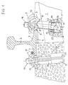
- 1 and 2 is the rail fastening according to the invention on the left half of the picture in the Final assembly position and on the right half of the picture in the Pre-assembled position shown, namely in Fig. 1 in a central longitudinal section through a concrete sleeper 1 and in Fig. 2 in a plan view, but the Concrete sleeper omitted and the rail 2 outside the Epsilon-shaped clamping springs 3 is cut off.
- the left side shows the track exterior and the right side the track interior, with the rail 2 in the track exterior in the assembled state and in the track interior in pre-assembled state is shown.
- the rail 2 the here using the example of the well-known UIC 60 rail profile is shown using a vibration damping Liner 4 on the concrete sleeper 1 between two angular guide plates 5, the Rail axis in a known manner in a fixed Ratio of e.g. 1:40 compared to the vertical to Track interior is inclined.
- the angular ones Guide plates 5 each have a longitudinal rib 6, with which they rest on the rail foot 7.
- the guide plates 5 each have an inclined surface 8 with which they the side facing away from the rail 2 on one corresponding support surface 9 of a recess 10 in the Apply concrete sleeper 1.
- Anchor elements 15, each having a clamping spring 3 holding head 16 and an angled end 17th have, which on a within the concrete sleeper 1st stored cam 18 attacks.
- the cams 18 are each inserted in a plastic housing 19, with which they are used in the manufacture of the concrete sleeper 1 poured into the concrete mass.
- the housing 19 can be aligned obliquely so that the central axis of the anchor element 15 used therein Intersects the rail axis below the rail (see Fig. 1).
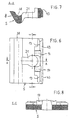
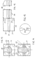
- the housing 19 is composed of two parts 20, 21 together, with a slight press fit through a tongue and groove connection 22 can be positively connected to one another are (see Figs. 14 and 15).
- the housing 19 forms a chamber-like section 23, which has a rectangular cross section.
- the Cam 18 is accordingly with an im provided substantially rectangular shaped paragraph 24, such as can be seen particularly well in FIG. 9.
- Paragraph 24 is in the upper area of the chamber-like Housing section 23 by four lying in one plane Support ribs 25 held so that the cam 18 in the axial direction of the anchor element 15 is fixed.
- On the chamber-shaped section 23 closes in the direction a tubular housing section of the threshold top 26 with a keyhole-shaped cross section one round and one essentially rectangular Has partial area 27 or 28.
- the rectangular one Partial area 28 is bevelled on the upper side, so that the Housing 19 in concrete just below each Recess 10 arranged for the angle guide plate 5 can be.
- the housing 19 is on the underside an opening 29 provided with a recess 30 in the underside of the threshold meets (see FIG. 1).
- the anchor element 15 can with its angled End section 17 from the top of the concrete sleeper 1 through an elongated hole-like opening 31 within the Guide plate 5 through the channel-shaped Section 26 in the chamber-like housing section 23 be introduced.
- the Cam 18 on a U-shaped opening 32 with the channel-shaped housing section 26 meets, so that the angled end 17 of the anchor element 15th easily pass cam 18 and on it can attack on the underside.
- the cam disc 18 has a first ramp-shaped Section 33 with a relatively large slope on the passes into a first trough-shaped locking step 34. On this first locking step 34 closes a second ramped section 35, which is a smaller Has slope and into a second trough-shaped Locking step 36 passes (see. Fig. 9 to 11).
- the first Locking step 34 serves to lock the anchor element 15 in the pre-assembly position.
- the epsilon-shaped Clamping springs 3 After the rail 2 between the angle guide plates 5 using the liner 4 on the Concrete sleeper 1 is placed, the epsilon-shaped Clamping springs 3 from the pre-assembly position in Pushed towards the rail 2 so that their free Press leg ends 12 onto the rail foot 7 and the leg 37 facing away from rail 2 in the longitudinal groove 38 engage the guide plate 5.
- the angled end section 17 becomes the final assembly position of the anchor element 15 then from the first latching step 34 via the second ramp-shaped section 35 into the second locking step 36 rotated and finally there again locked.
- the shaft of the anchor element 15 looping middle part 39 of the clamping spring 3 comes at a slight distance above the rail foot 7 lie. In this way, the rail 1 with a certain tension force pressed onto the concrete sleeper 1 (see right and left half of Fig. 1).
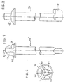
- the rod-shaped anchor element 15 can be released instead a railroad sleeper screw head 16 preferably a specially designed head 40 exhibit.
- 4 and 5 is an example of one such special anchor element 15 'shown.
- the head 40 this anchor element 15 ' has three at about 120 ° offset polygonal attachment surfaces 41 for one appropriately trained special keys.
- At the The top of the head 40 is also a bore 42 arranged in the one on the special key (not shown) provided guide pin can be inserted.
Abstract
Description
Die vorliegende Erfindung betrifft eine auf Betonschwellen oder dergleichen vormontierbare Schienenbefestigung, die beidseitig der Schiene an der Schienenbefestigungsstelle angeordnet ist und jeweils eine elastische Klemmfeder und eine winkelförmige Führungsplatte aufweist, wobei die Führungsplatte mit einer Seite am Schienenfuß und auf der der Schiene abgewandten Seite mit einer Schrägfläche an einer entsprechenden Stützfläche einer Aussparung der Betonschwelle oder dergleichen anliegt und wobei die Führungsplatte und die Klemmfeder mittels eines in der Betonschwelle oder dergleichen verankerten Befestigungsmittels in ihrer Vormontagestellung gehalten werden und die Klemmfeder in der Endmontagestellung auf den Schienenfuß drückt.The present invention relates to a Concrete sleepers or the like pre-assembled Rail fastening, which is on both sides of the rail on the Rail attachment point is arranged and each an elastic clamp spring and an angular one Has guide plate, the guide plate with one side on the rail foot and on that of the rail opposite side with an inclined surface on one corresponding support surface of a recess Concrete sleeper or the like is applied and the Guide plate and the clamping spring by means of a in the Anchored concrete sleeper or the like Fasteners held in their pre-assembly position be and the clamping spring in the final assembly position presses the rail foot.
Eine derartige Schienenbefestigung ist aus der DE 39 18 091 A1 bekannt. Als Befestigungsmittel dienen dort Schwellenschrauben, die unter Verwendung von Kunststoffdübeln in entsprechende Löcher der Betonschwellen eingeschraubt werden. Bei den mittels der Schwellenschrauben gehaltenen Klemmfedern handelt es sich um besonders ausgestaltete Spannklemmen aus Stabstahl, die zusammen mit Winkelführungsplatten an den Betonschwellen vormontiert werden. Die Spannklemmen werden aus der Vormontagestellung heraus soweit in Richtung auf die Schiene verschoben, bis sie auf der der Schiene abgewandten Seite in eine in der Winkelführungsplatte ausgebildete Führungsrille eingreifen und ihre freien Enden auf den Schienenfuß drücken. In dieser Stellung erfolgt dann die Entmontage, indem die Schwellenschrauben mittels eines Drehmomentschlüssels soweit angezogen werden, bis eine gewünschte Spannkraft erreicht ist, wobei der Mittelteil der Spannklemme in einem geringem Abstand über dem Schienenfuß zu liegen kommt.Such a rail attachment is from the DE 39 18 091 A1 known. Serve as a fastener there threshold screws that using Plastic dowels in corresponding holes in the Concrete sleepers are screwed in. In the case of the Clamp springs held by sleeper screws around specially designed tension clamps made of steel bars, which together with angle guide plates on the Pre-assembled concrete sleepers. The tension clamps from the pre-assembly position as far as Moved towards the rail until it was on the Side facing away from the rail in a in the angle guide plate engage trained guide groove and press their free ends onto the rail foot. In this The position is then dismantled by the Threshold screws using a torque wrench be tightened until a desired clamping force is reached, the middle part of the tension clamp in one comes to a small distance above the rail foot.
Diese bekannte Schienenbefestigung zeichnet sich durch eine einfache Vormontage sowie einen einfachen Übergang von der Vormontage- in die Endmontagestellung nach Einlegen der Schiene aus. Zudem stellen die Winkelführungsplatten sicher, daß Horizontalkräfte direkt auf die Betonschwellen übertragen werden und somit nur reine Zugkräfte auf die Schwellenschrauben wirken, so daß sich diese nicht selbsttätig lösen können.This known rail fastening is characterized by a easy pre-assembly as well as a simple transition from the Pre-assembly in the final assembly position after inserting the Rail off. In addition, the angle guide plates sure that horizontal forces are directly on the concrete sleepers are transmitted and thus only pure tensile forces on the Threshold screws act so that they do not can solve automatically.
Gleichwohl sind viele Eisenbahningenieure unverständlicherweise der Meinung, daß geschraubte Schienenbefestigungssysteme wartungsintensiv seien, weil sich Schraubverbindungen selbsttätig lösen würden, wohingegen schraublose Systeme wartungsarm oder sogar wartungsfrei seien.However, many railway engineers are incomprehensible believe that bolted rail fastening systems are maintenance-intensive because Would loosen screw connections automatically, whereas screwless systems require little or no maintenance are.
Schraublose Schienenbefestigungssysteme erfordern spezielle Verankerungen in den Schwellen. Es sind Systeme bekannt, bei denen Federn beispielsweise schienenparallel oder senkrecht zur Schiene eingefädelt werden. Auch existieren im Stand der Technik Systeme, bei welchen ein Federende in eine Öffnung eingesteckt wird, um danach das zweite Federende mittels Hebel in eine zweite halboffene Halterung einzusetzen.Screwless rail fastening systems require special Anchoring in the sleepers. Systems are known where springs, for example, parallel to the rail or be threaded perpendicular to the rail. Also exist in the prior art systems in which a spring end in one opening is inserted, after which the second Spring end by lever into a second half-open bracket use.
Aus der EP 0 373 099 A1 ist eine auf Betonschwellen vormontierte Schienenbefestigung bekannt, die eine elastische Klemmfeder und eine winkelförmige Führungsplatte aufweist. Die Klemmfeder ist mit einem daran einstückig ausgebildeten Befestigungsmittel in Form eines Ankerelements versehen, das in einer in der Betonschwelle eingegossenen Hülse verankerbar ist. Hierzu ist die Hülse an ihrem einen Ende mit einer radialen Erweiterung versehen, in die ein am Ende des Ankerelements radial abstehender Absatz hineingedreht werden kann. Das Spannen der Klemmfeder erfolgt dabei dadurch, daß diese mit einer auf der Führungsplatte angeordneten Rampe zusammenwirkt. Die Führungsplatte ist relativ flach ausgebildet. Dementsprechend liegt sie an ihrer der Schiene abgewandten Seite an einer nur relativ kleinen, im wesentlichen lotrechten Stützfläche einer Aussparung der Betonschwelle an. Über diese Führungsplatte lassen sich daher nur relativ geringe Horizontalkräfte in die Betonschwelle einleiten.EP 0 373 099 A1 describes one on concrete sleepers pre-assembled rail fastener known, the one elastic clamping spring and an angular guide plate having. The clamping spring is in one piece with it trained fasteners in the form of a Anchor element provided in a concrete sleeper cast sleeve is anchored. For this is the sleeve at one end with a radial extension provided, in the radial at the end of the anchor element protruding paragraph can be screwed. The tension the clamping spring takes place in that this with a cooperates on the guide plate arranged ramp. The guide plate is relatively flat. Accordingly, it is due to its facing away from the rail Side on a relatively small, essentially vertical support surface of a recess in the concrete sleeper on. This guide plate can therefore only be used relatively Introduce low horizontal forces into the concrete sleeper.
Der vorliegenden Erfindung liegt die Aufgabe zugrunde, eine Schienenbefestigung der eingangs genannten Art so zu verbessern, daß diese neben den Vorteilen der geschraubten Schienenbefestigungssyteme, wie der direkten Ableitung von Horizontalkräften in den Betonkörper, eine noch schnellere und einfachere Schienenmontage ermöglicht.The present invention is based on the object a rail fastening of the type mentioned above improve that besides the benefits of screwed Rail fastening systems, such as the direct derivation of Horizontal forces in the concrete body, an even faster and easier rail mounting.
Diese Aufgabe wird dadurch gelöst, daß das Befestigungsmittel ein Ankerelement ist, das an einer innerhalb der Schwelle gelagerten Kurvenscheibe angreift, die beim Verdrehen des Ankerelements ein Spannen der Klemmfeder bewirkt. Die erfindungsgemäße Lösung stellt eine Art Schnellverschluß dar, der eine nahezu narrensichere Schienenmontage gewährleistet. Durch Beibehaltung der für sich genommen bekannten winkelförmigen Führungsplatte wird dabei wiederum sichergestellt, daß lediglich Zugkräfte, jedoch keine Scherkräfte auf das Ankerelement wirken. Als Klemmfedern können z.B. Spannklemmen, sogenannte Fast-clips oder dergleichen zum Einsatz kommen. This object is achieved in that the fastener is an anchor element attached to one within the Threshold mounted cam plate attacks when Twisting the anchor element tensioning the clamping spring causes. The solution according to the invention represents a kind Quick release represents an almost foolproof Rail assembly guaranteed. By maintaining the for taken known angular guide plate this in turn ensures that only tensile forces, however, no shear forces act on the anchor element. As Clamping springs can e.g. Tension clamps, so-called fast clips or the like are used.
Eine bevorzugte Ausgestaltung der erfindungsgemäßen Schienenbefestigung ist dadurch gekennzeichnet, daß die Kurvenscheibe stufenförmig ausgebildet ist und mindestens einen rampenförmigen Abschnitt aufweist, über den die Klemmfeder bei Verdrehen des Ankerelements gespannt wird. Das Ankerelement ist vorzugsweise arretierbar. Zur Arretierung des Ankerelements können in der Kurvenscheibe ein oder auch mehrere Raststufen ausgebildet seien, denen unterschiedliche Spannungsgrade der Klemmfeder zugeordnet sind.A preferred embodiment of the invention Rail fastening is characterized in that the Cam is stepped and at least has a ramp-shaped section over which the Clamping spring is tensioned when the anchor element is rotated. The anchor element is preferably lockable. to The anchor element can be locked in the cam disc one or more rest stages are formed, which different degrees of tension assigned to the clamping spring are.
Nach einer besonders bevorzugten Ausgestaltung ist vorgesehen, daß die Kurvenscheibe einen ersten ansteigenden rampenförmigen Abschnitt aufweist, der in eine erste Raststufe übergeht, an die sich ein wiederum ansteigender zweiter rampenförmiger Abschnitt anschließt, der in eine zweite Raststufe übergeht, wobei die erste Raststufe einer Vormontagestellung und die zweite Raststufe einer Endmontagestellung entspricht. Die rampenförmigen Abschnitte können unterschiedliche Steigungen aufweisen, wobei vorzugsweise die Steigung des ersten Abschnittes größer ist als die des zweiten Abschnittes. Auf diese Weise kann die Drehmomentzunahme beim Spannen der Klemmfeder herabgesetzt werden, so daß das Verdrehen des Ankerelementes in die Endmontagestellung entsprechend erleichtert wird.According to a particularly preferred embodiment provided that the cam disc a first rising has ramp-shaped section, which in a first Resting stage passes, to which an in turn increases second ramp-shaped section that connects into a second rest stage passes, the first rest stage one Pre-assembly position and the second locking step one Final assembly position corresponds. The ramped sections can be different Have slopes, preferably the slope of the first section is larger than that of the second Section. In this way, the torque increase be reduced when tensioning the clamping spring, so that turning the anchor element into the final assembly position is relieved accordingly.
Eine einfache und kostengünstig realisierbare Verankerung ergibt sich, wenn das Ankerelement mit einem abgewinkelten Endabschnitt an der Kurvenscheibe angreift. Alternativ können aber an dem Ankerelement auch mehrere Ankerkrallen ausgebildet sein.A simple and inexpensive anchoring results when the anchor element with a angled end portion attacks on the cam. Alternatively, however, several can also be attached to the anchor element Anchor claws should be formed.
Zum Ansatz eines Schraubenschlüssels oder eines anderen geeigneten Werkzeuges kann das Ankerelement einen genormten eisenbahnüblichen Schraubenkopf aufweisen. Alternativ kann es aber auch zweckmäßig sein, wenn der Kopf des Ankerelements so ausgestaltet ist, daß daran nur ein spezieller, jedoch kein im Handel erhältlicher Schraubenschlüssel angesetzt werden kann. Auf diese Weise wird ein Lösen der Verankerung durch Unbefugte verhindert oder zumindest erschwert. Beispielsweise kann das Ankerelement einen innenliegenden Schlüsselansatz aufweisen und/oder mit einem Durchbruch oder Halteteil zum Ansatz einer Querstange versehen sein.To attach a wrench or another suitable tool, the anchor element have standardized railroad screw head. Alternatively, it can also be useful if the Head of the anchor element is designed so that only a special one, but not a commercially available one Wrench can be attached. In this way unauthorized persons prevent the anchoring from being loosened or at least difficult. For example, that Anchoring element an internal key approach have and / or with an opening or holding part be provided for the attachment of a crossbar.
Nach einer anderen vorteilhaften Ausgestaltung ist vorgesehen, daß die Kurvenscheibe in einem in der Betonschwelle angeordneten Gehäuse gehalten ist, das vorzugsweise aus Kunststoff besteht. Auf diese Weise ist es möglich, die Kurvenscheibe mit dem Gehäuse direkt in der Betonschwelle bei deren Herstellung zu integrieren. Das Gehäuse dient dabei als Platzhalter sowie der elektrischen Gleisisolierung, sofern es aus Kunststoff oder einem anderen elektrisch isolierenden Material gefertigt ist.According to another advantageous embodiment provided that the cam in one in the Concrete sleeper arranged housing is held that preferably consists of plastic. That way it is possible to put the cam with the housing directly in to integrate the concrete sleeper in its manufacture. The housing serves as a placeholder and the electrical track insulation, provided it is made of plastic or another electrically insulating material is made.
Zur elektrischen Gleisisolierung kann auch die Kurvenscheibe aus Kunststoff bestehen und/oder das Ankerelement mit einem Kunststoffmantel umspritzt oder überzogen sein. Ferner kann das Ankerelement auch in einer Hülse aus Kunststoff oder einem anderen elektrisch isolierenden Material angeordnet werden.The can also be used for electrical track insulation Cam made of plastic and / or that Overmolded anchor element with a plastic jacket or be covered. Furthermore, the anchor element can also be in a sleeve made of plastic or another electrical insulating material.
Weitere vorteilhafte Ausgestaltungen der erfindungsgemäßen Schienenbefestigung sind in den Unteransprüchen gekennzeichnet.Further advantageous embodiments of the Rail fastening according to the invention are in the Subclaims marked.
Nachfolgend wird die Erfindung anhand von Ausführungsbeispielen und mit Bezug auf die beiliegende Zeichnung näher erläutert. Es zeigen:
- Fig. 1
- einen Querschnitt durch ein Schienenprofil mit einer erfindungsgemäßen Schienenbefestigung, bei welchem die linke Seite die Endmontagestellung im Gleisaußenraum und die rechte Seite die Vormontagestellung im Gleisinnenraum im Schnitt darstellt;
- Fig. 2
- eine Draufsicht auf das Schienenprofil und die Schienenbefestigung gemäß Fig. 1;
- Fig. 3
- in Seitenansicht ein stangenförmiges Ankerelement mit einem Vierkantkopf und einem abgewinkelten Endabschnitt;
- Fig. 4
- in Seitenansicht ein anderes Ausführungsbeispiel eines stangenförmigen Ankerelements mit einem besonders ausgestalteten Kopfabschnitt;
- Fig. 5
- eine Draufsicht auf den Kopfabschnitt gemäß Fig. 4;
- Fig. 6
- eine Draufsicht auf eine Winkelführungsplatte für die erfindungsgemäße Schienenbefestigung;
- Fig. 7
- einen Querschnitt durch die Winkelführungsplatte gemäß Fig. 6 entlang der Linie A-A;
- Fig. 8
- einen Querschnitt durch die Winkelführungsplatte gemäß Fig. 6 entlang der Linie E-E;
- Fig. 9
- eine Draufsicht auf eine Kurvenscheibe für die erfindungsgemäße Schienenbefestigung;
- Fig. 10
- einen Querschnitt durch die Kurvenscheibe gemäß Fig. 9 entlang der Linie A-A;
- Fig. 11
- den abgewickelten Außendurchmesser der Kurvenscheibe gemäß Fig. 9;
- Fig. 12
- eine Seitenansicht eines zweiteiligen, in Längsrichtung geteilten Gehäuses zur Aufnahme der Kurvenscheibe;
- Fig. 13
- eine Draufsicht auf das Gehäuse gemäß Fig. 12 in zusammengesetztem Zustand;
- Fig. 14
- eine Draufsicht auf das Gehäuse gemäß Fig. 12 in geöffnetem Zustand; und
- Fig. 15
- eine vergrößerte schematische Darstellung des Details Z der Fig. 14.
- Fig. 1
- a cross section through a rail profile with a rail fastening according to the invention, in which the left side represents the final assembly position in the track exterior and the right side the pre-assembly position in the track interior in section;
- Fig. 2
- a plan view of the rail profile and the rail fastening according to FIG. 1;
- Fig. 3
- in side view a rod-shaped anchor element with a square head and an angled end portion;
- Fig. 4
- in side view another embodiment of a rod-shaped anchor element with a specially designed head portion;
- Fig. 5
- a plan view of the head portion of FIG. 4;
- Fig. 6
- a plan view of an angle guide plate for the rail fastening according to the invention;
- Fig. 7
- a cross section through the angle guide plate of FIG 6 along the line AA.
- Fig. 8
- a cross section through the angle guide plate of FIG 6 along the line EE.
- Fig. 9
- a plan view of a cam for the rail fastening according to the invention;
- Fig. 10
- a cross section through the cam according to FIG 9 along the line AA.
- Fig. 11
- the unwound outer diameter of the cam according to FIG. 9;
- Fig. 12
- a side view of a two-part, longitudinally divided housing for receiving the cam;
- Fig. 13
- a plan view of the housing of FIG 12 in the assembled state.
- Fig. 14
- a plan view of the housing of FIG 12 in the open state. and
- Fig. 15
- an enlarged schematic representation of the detail Z of FIG. 14th
In den Fig. 1 und 2 ist die erfindungsgemäße Schienenbefestigung
auf der linken Bildhälfte jeweils in der
Endmontagestellung und auf der rechten Bildhälfte in der
Vormontagestellung dargestellt, und zwar in Fig. 1 in
einem Mittellängsschnitt durch eine Betonschwelle 1 und
in Fig. 2 in einer Draufsicht, wobei jedoch die
Betonschwelle weggelassen und die Schiene 2 außerhalb der
Epsilonförmigen Klemmfedern 3 abgeschnitten ist. Die
linke Seite zeigt den Gleisaußenraum und die rechte Seite
den Gleisinnenraum, wobei die Schiene 2 im Gleisaußenraum
im montierten Zustand und im Gleisinnenraum im
vormontierten Zustand dargestellt ist.1 and 2 is the rail fastening according to the invention
on the left half of the picture in the
Final assembly position and on the right half of the picture in the
Pre-assembled position shown, namely in Fig. 1 in
a central longitudinal section through a
Wie in Fig. 1 zu erkennen ist, liegt die Schiene 2, die
hier am Beispiel des bekannten Schienenprofils UIC 60
gezeigt ist, unter Verwendung einer schwingungsdämpfenden
Zwischenlage 4 auf der Betonschwelle 1 zwischen zwei
winkelförmigen Führungsplatten 5 auf, wobei die
Schienenachse in bekannter Weise in einem festgelegten
Verhältnis von z.B. 1:40 gegenüber der Vertikalen zum
Gleisinnenraum hin geneigt ist. Die winkelförmigen
Führungsplatten 5 weisen je eine Längsrippe 6 auf, mit
der sie am Schienenfuß 7 anliegen. Die Führungsplatten 5
weisen ferner je eine Schrägfläche 8 auf, mit der sie auf
der der Schiene 2 abgewandten Seite an einer
entsprechenden Stützfläche 9 einer Aussparung 10 in der
Betonschwelle 1 anliegen.As can be seen in Fig. 1, the
Durch die relativ lange Form der Innenschenkel 11 der
Klemmfeder 3 ist es möglich, die Klemmfeder 3 ohne
Verdrehen aus der Vormontagestellung in die
Endmontagestellung zu verschieben, wobei die freien Enden
12 der Klemmfeder 3 aus ihrer Vormontagestellung an den
Anschlägen 13 der Längsrippe 6 der Führungsplatte 5 über
die Schrägfläche 43 an der dem Schienenfuß 7 benachbarten
Oberkante der Längsrippe 6 auf den Schienenfuß 7 gleiten.
Die Innenschenkel 11 der Klemmfeder 3 werden dabei
entlang den inneren Führungsrinnen 14 der Führungsplatte
5 geführt.Due to the relatively long shape of the
Als Befestigungsmittel dienen stangenförmige
Ankerelemente 15, die jeweils einen die Klemmfeder 3
haltenden Kopf 16 sowie ein abgewinkeltes Ende 17
aufweisen, welches an einer innerhalb der Betonschwelle 1
gelagerten Kurvenscheibe 18 angreift. Die Kurvenscheiben
18 sind jeweils in einem Kunststoffgehäuse 19 eingesetzt,
mit dem sie bei der Herstellung der Betonschwelle 1 in
der Betonmasse eingegossen werden. Das Gehäuse 19 kann
dabei schräg ausgerichtet sein, so daß die Mittelachse
des darin eingesetzten Ankerelementes 15 die
Schienenachse unterhalb der Schiene schneidet (vgl. Fig.
1). Das Gehäuse 19 setzt sich aus zwei Teilen 20, 21
zusammen, die mit leichtem Klemmsitz durch eine Nut-Feder-Verbindung
22 formschlüssig miteinander verbindbar
sind (vgl. Fig. 14 und 15). Im zusammengesetzten Zustand
bildet das Gehäuse 19 einen kammerartigen Abschnitt 23,
der einen rechteckigen Querschnitt besitzt. Die
Kurvenscheibe 18 ist dementsprechend mit einem im
wesentlichen rechteckig geformten Absatz 24 versehen, wie
besonders gut in Fig. 9 zu erkennen ist. Der Absatz 24
ist im oberen Bereich des kammerartigen
Gehäuseabschnittes 23 durch vier in einer Ebene liegende
Stützrippen 25 gehalten, so daß die Kurvenscheibe 18 in
der Axialrichtung des Ankerelements 15 fixiert ist. An
den kammerförmigen Abschnitt 23 schließt sich in Richtung
der Schwellenoberseite ein rohrförmiger Gehäuseabschnitt
26 an, der einen schlüssellochförmigen Querschnitt mit
einem runden und einem im wesentlichen rechteckigen
Teilbereich 27 bzw. 28 aufweist. Der rechteckige
Teilbereich 28 ist oberseitig abgeschrägt, so daß das
Gehäuse 19 im Beton dicht unterhalb der jeweiligen
Aussparung 10 für die Winkelführungsplatte 5 angeordnet
werden kann. An der Unterseite ist das Gehäuse 19 mit
einer Öffnung 29 versehen, die mit einer Ausnehmung 30 in
der Schwellenunterseite zusammentrifft (vgl. Fig. 1).Rod-shaped are used as fasteners
Anchor
Das Ankerelement 15 kann mit seinem abgewinkelten
Endabschnitt 17 von der Oberseite der Betonschwelle 1 aus
durch eine langlochartige Öffnung 31 innerhalb der
Führungsplatte 5 hindurch über den kanalförmigen
Abschnitt 26 in den kammerartigen Gehäuseabschnitt 23
eingeführt werden. Wie Fig. 9 zeigt, weist die
Kurvenscheibe 18 eine U-förmige Öffnung 32 auf, die mit
dem kanalförmigen Gehäuseabschnitt 26 zusammentrifft, so
daß das abgewinkelte Ende 17 des Ankerelements 15
problemlos die Kurvenscheibe 18 passieren und daran
unterseitig angreifen kann.The
Die Kurvenscheibe 18 weist einen ersten rampenförmigen
Abschnitt 33 mit einer relativ großen Steigung auf, der
in eine erste muldenförmige Raststufe 34 übergeht. An
diese erste Raststufe 34 schließt sich ein zweiter
rampenförmiger Abschnitt 35 an, der eine geringere
Steigung besitzt und in eine zweite muldenförmige
Raststufe 36 übergeht (vgl. Fig. 9 bis 11). Die erste
Raststufe 34 dient der Arretierung des Ankerelementes 15
in der Vormontagestellung.The
Nachdem die Schiene 2 zwischen den Winkelführungsplatten
5 unter Verwendung der Zwischenlage 4 auf der
Betonschwelle 1 aufgelegt ist, werden die Epsilonförmigen
Klemmfedern 3 aus der Vormontagestellung in
Richtung auf die Schiene 2 geschoben, so daß ihre freien
Schenkelenden 12 auf den Schienenfuß 7 drücken und die
der Schiene 2 abgewandten Schenkel 37 in der Längsrille
38 der Führungsplatte 5 eingreifen. In dieser
Endmontagestellung wird der abgewinkelte Endabschnitt 17
des Ankerelements 15 dann von der ersten Raststufe 34
über den zweiten rampenförmigen Abschnitt 35 in die
zweite Raststufe 36 gedreht und dort schließlich wieder
arretiert. Der den Schaft des Ankerelements 15
umschlingende Mittelteil 39 der Klemmfeder 3 kommt dabei
in geringfügigem Abstand über dem Schienenfuß 7 zu
liegen. Auf diese Weise wird die Schiene 1 mit einer
bestimmten Spannkraft auf die Betonschwelle 1 gedrückt
(vgl. rechte und linke Bildhälfte der Fig. 1).After the
Zur Sicherung der Schienenbefestigung gegen unbefugtes
Lösen kann das stangenförmige Ankerelement 15 anstelle
eines eisenbahnüblichen Schwellenschraubenkopfes 16
vorzugsweise einen speziell ausgestalteten Kopf 40
aufweisen. In den Fig. 4 und 5 ist ein Beispiel eines
solchen Spezialankerelements 15' gezeigt. Der Kopf 40
dieses Ankerelements 15' weist drei um etwa 120°
versetzte mehrkantige Ansatzflächen 41 für einen
entsprechend ausgebildeten Spezialschlüssel auf. An der
Oberseite des Kopfes 40 ist zudem eine Bohrung 42
angeordnet, in die ein an dem Spezialschlüssel (nicht
gezeigt) vorgesehener Führungsstift einsteckbar ist. To secure the rail fastening against unauthorized persons
The rod-shaped
- 11
- Betonschwelleconcrete sleeper
- 22
- Schienerail
- 33
- Klemmfeder (Spannklemme)Clamp spring (tension clamp)
- 44
- Zwischenlageliner
- 55
- WinkelführungsplatteAngled guide plate
- 66
-
Längsrippe an der Winkelführungsplatte 5Longitudinal rib on the
angle guide plate 5 - 77
- Schienenfußrail
- 88th
-
Schrägfläche an der Winkelführungsplatte 5Sloping surface on the
angle guide plate 5 - 99
-
Stützfläche an der Betonschwelle 1Support surface on the
concrete sleeper 1 - 1010
-
Aussparung in der Betonschwelle 1Recess in the
concrete sleeper 1 - 1111
-
Innenschenkel der Federklemme 3Inner leg of the
spring clip 3 - 1212
-
freie Schenkelenden der Federklemme 3free leg ends of the
spring clip 3 - 1313
-
Anschläge an der Winkelführungsplatte 5Stops on the
angle guide plate 5 - 1414
-
innere Führungsrinnen der Winkelführungsplatte 5inner guide troughs of the
angle guide plate 5 - 1515
- Ankerelementanchor member
- 1616
- VierkantschraubenkopfSquare screw head
- 1717
-
abgewinkelter Endabschnitt des Ankerelements 15angled end section of the
anchor element 15 - 1818
- Kurvenscheibecam
- 1919
- Gehäusecasing
- 2020
- erstes Gehäuseteilfirst housing part
- 2121
- zweites Gehäuseteilsecond housing part
- 2222
- Feder-Nut-VerbindungTongue and groove connection
- 2323
- kammerartiger Gehäuseabschnittchamber-like housing section
- 2424
-
Absatz an der Kurvenscheibe 18Heel on
cam 18 - 2525
- Stützrippensupport ribs
- 2626
- rohrförmiger Gehäuseabschnitttubular housing section
- 2727
-
runder Teilbereich des rohrförmigen Abschnittes 26round section of the
tubular section 26 - 2828
-
rechteckiger Teilbereich des rohrförmigen Abschnittes
26rectangular section of the
tubular section 26 - 2929
- unterseitige Gehäuseöffnungbottom housing opening
- 3030
-
Ausnehmung in der Betonschwelle 1Recess in the
concrete sleeper 1 - 3131
-
Öffnung in der Winkelführungsplatte 5Opening in the
angle guide plate 5 - 3232
-
U-förmige Öffnung der Kurvenscheibe 18 U-shaped opening of the
cam disk 18 - 3333
-
erster rampenförmiger Abschnitt der Kurvenscheibe 18first ramp-shaped section of the
cam disk 18 - 3434
-
erste Raststufe der Kurvenscheibe 18first locking stage of the
cam disk 18 - 3535
-
zweiter rampenförmiger Abschnitt der Kurvenscheibe 18second ramp-shaped section of the
cam disk 18 - 3636
-
zweite Raststufe der Kurvenscheibe 18second locking stage of the
cam disk 18 - 3737
-
von der Schiene 2 abgewandte Schenkel der Klemmfeder 3leg of the
clamping spring 3 facing away from therail 2 - 3838
-
Führungsrille in der Winkelführungsplatte 5Guide groove in the
angle guide plate 5 - 3939
- Mittelteil der Klemmfeder (Spannklemme) 3Middle part of the clamping spring (tension clamp) 3
- 4040
- Ankerkopfanchor head
- 4141
- Ansatzflächen für SpezialwerkzeugAttachment surfaces for special tools
- 4242
-
Bohrung im Ankerkopf 40Hole in
anchor head 40
Claims (18)
- A rail fastening that can be pre-mounted on concrete railroad ties (1) or the like and is arranged on both sides of the rail (2) at the rail fastening point, wherein the respective rail fastening contains an elastic clamping spring (3) and an angular guide plate (5), wherein the guide plate (5) adjoins the rail base (7) with one side and a corresponding support surface of a recess in the concrete railroad tie (1) or the like with an inclined surface (8) on the side that faces away from the rail (2), wherein the guide plate (5) and the clamping spring (3) are held in their pre-fastening position by means of a fastening means that is anchored in the concrete railroad tie (1) or the like, and wherein the clamping spring (3) presses on the rail base (7) in the fastened position, characterized by the fact that the fastening means consists of an anchor element (15) that engages on a cam plate (18) arranged within the railroad tie (1), with said cam plate causing the clamping spring (3) to be tensioned when the anchor element (15) is turned.
- A rail fastening according to claim 1, characterized by the fact that the cam plate (18) is formed in a stepped fashion and contains at least one ramp-shaped section (33; 35).
- A rail fastening according to claim 1 or 2, characterized by the fact that the cam plate (18) contains one or more catch steps (34; 36).
- A rail fastening according to claim 2 or 3, characterized by the fact that the cam plate (18) contains a first ascending ramp-shaped section (33) that transforms into a first catch step (34), with the first catch step being followed by a second ascending ramp-shaped section (35) that transforms into a second catch step (36), and with the first catch step (34) corresponding to a pre-fastening position and the second catch step (35) corresponding to a fastened position.
- A rail fastening according to claim 4, characterized by the fact that the ramp-shaped sections (33; 35) have different inclines.
- A rail fastening according to one of the preceding claims, characterized by the fact that the anchor element (15) contains an angled end section (17) that engages on the cam plate (18).
- A rail fastening according to one of the preceding claims, characterized by the fact that the anchor element (15) contains a standardized screw head (16).
- A rail fastening according to one of claims 1-6, characterized by the fact that the anchor element (15) contains a head (40) onto which a special wrench can be positively attached, wherein commercially available wrenches cannot be positively attached to said head such that the anchor element (15) cannot be loosened by unauthorized persons.
- A rail fastening according to one of the preceding claims, characterized by the fact that the cam plate (18) is held in a housing (19) arranged in the concrete railroad tie (1).
- A rail fastening according to claim 9, characterized by the fact that the housing (19) consists of plastic.
- A rail fastening according to one of the preceding claims, characterized by the fact that the anchor element (15) is provided with a plastic jacket.
- A rail fastening according to one of the preceding claims, characterized by the fact that the anchor element (15) is arranged in a sleeve of plastic or another electrically insulating material.
- A rail fastening according to one of the preceding claims, characterized by the fact that the clamping spring (3) can be displaced from the pre-fastening position into the fastened position.
- A rail fastening according to one of the preceding claims, characterized by the fact that the guide plate (5) contains a guide groove (38) into which the clamping spring (3) engages in the fastened position.
- A rail fastening according to claim 14, characterized by the fact that the guide plate (5) contains an oblong opening (31) through which the angled end section (17) of the anchor element (15) can be inserted.
- A rail fastening according to claim 14 or 15, characterized by the fact that the clamping spring (3) consists of a tensioning clamp which is bent such that its inner limbs (11) are looped around the anchor element (15) and overlapped by the anchor element (15).
- A rail fastening according to claim 16, characterized by the fact that the guide plate (5) is provided with limit stops (13) that are adjoined by the free ends (12) of the tensioning clamp (3) in the pre-fastening position.
- A rail fastening according to claim 16, characterized by the fact that the tension spring (3) consists of a tensioning clamp that is formed in the shape of a epsilon.
Priority Applications (3)
| Application Number | Priority Date | Filing Date | Title |
|---|---|---|---|
| EP96108053A EP0808946B1 (en) | 1996-05-21 | 1996-05-21 | Rail fastening |
| AT96108053T ATE215150T1 (en) | 1996-05-21 | 1996-05-21 | RAIL FASTENING |
| DE59608964T DE59608964D1 (en) | 1996-05-21 | 1996-05-21 | rail fastening |
Applications Claiming Priority (1)
| Application Number | Priority Date | Filing Date | Title |
|---|---|---|---|
| EP96108053A EP0808946B1 (en) | 1996-05-21 | 1996-05-21 | Rail fastening |
Publications (2)
| Publication Number | Publication Date |
|---|---|
| EP0808946A1 EP0808946A1 (en) | 1997-11-26 |
| EP0808946B1 true EP0808946B1 (en) | 2002-03-27 |
Family
ID=8222803
Family Applications (1)
| Application Number | Title | Priority Date | Filing Date |
|---|---|---|---|
| EP96108053A Expired - Lifetime EP0808946B1 (en) | 1996-05-21 | 1996-05-21 | Rail fastening |
Country Status (3)
| Country | Link |
|---|---|
| EP (1) | EP0808946B1 (en) |
| AT (1) | ATE215150T1 (en) |
| DE (1) | DE59608964D1 (en) |
Families Citing this family (9)
| Publication number | Priority date | Publication date | Assignee | Title |
|---|---|---|---|---|
| DE19807627A1 (en) * | 1998-02-23 | 1999-08-26 | Ortwein | Substructure for a track formed by rails for rail vehicles |
| DE102005058465A1 (en) * | 2005-12-07 | 2007-06-28 | Db Netz Ag | Fasteners for fastening railway tracks on track sleepers or railways |
| ITTV20060051A1 (en) | 2006-03-30 | 2007-09-30 | Emmetechnic Srl | ELASTIC ELEMENT |
| ES2283235B1 (en) | 2007-04-04 | 2009-03-01 | Mondragon Soluciones, S.L.U. | SHEATH FOR RAIL RAIL FASTENINGS, PROCEDURE FOR REPLACING SUCH SHEATH ON A CROSS AND TOOLS TO EXECUTE SUCH PROCEDURE. |
| DK2410090T3 (en) * | 2010-07-19 | 2015-06-22 | Schwihag Ag | Rail Fastening System |
| DE102010060745A1 (en) | 2010-11-23 | 2012-05-24 | Vossloh-Werke Gmbh | Guide plate for laterally guiding a rail and system for fastening a rail |
| DE102012003989B4 (en) | 2012-02-28 | 2022-06-09 | Elisabeth Ortwein | Substructure for a track formed from rails for rail vehicles |
| CN109910165A (en) * | 2019-03-21 | 2019-06-21 | 北京好运达智创科技有限公司 | For installing the swelled locating shaft of high iron sleeper service sleeve |
| CN110359325A (en) * | 2019-08-02 | 2019-10-22 | 太仓中博铁路紧固件有限公司 | A kind of fastener package assembly of rail and corresponding rail installation method |
Family Cites Families (3)
| Publication number | Priority date | Publication date | Assignee | Title |
|---|---|---|---|---|
| DE8505959U1 (en) * | 1985-03-01 | 1985-06-27 | Vossloh-Werke Gmbh, 5980 Werdohl | Kit for fastening rails |
| FR2639971B1 (en) * | 1988-12-02 | 1991-02-08 | Vape Sa Ets | FLANGE FOR QUICK FIXING OF A RAILWAY RAIL AND CROSS-SECTION PROVIDED WITH SUCH A FLANGE |
| DE8906790U1 (en) * | 1989-06-02 | 1989-08-31 | Vossloh-Werke Gmbh, 5980 Werdohl, De |
-
1996
- 1996-05-21 DE DE59608964T patent/DE59608964D1/en not_active Expired - Lifetime
- 1996-05-21 AT AT96108053T patent/ATE215150T1/en not_active IP Right Cessation
- 1996-05-21 EP EP96108053A patent/EP0808946B1/en not_active Expired - Lifetime
Also Published As
| Publication number | Publication date |
|---|---|
| DE59608964D1 (en) | 2002-05-02 |
| EP0808946A1 (en) | 1997-11-26 |
| ATE215150T1 (en) | 2002-04-15 |
Similar Documents
| Publication | Publication Date | Title |
|---|---|---|
| DE102007045466B3 (en) | System for fastening a rail | |
| DE102008003744B3 (en) | Support for a system for securing a rail and system for fastening a rail | |
| DE2314168C3 (en) | One-piece anchor element for stud bolts | |
| DD291593A5 (en) | RAIL MOUNTING ON CONCRETE SHAFTS OD. DGL. BY ELASTIC TERMINALS | |
| DE102005000129A1 (en) | Fastening device for fixing solar panels to a mounting rail | |
| EP2246577B1 (en) | Fastening element | |
| EP0808946B1 (en) | Rail fastening | |
| EP0194550B1 (en) | Securing clamp and fastening device for railway rails | |
| DE102006024440B4 (en) | Screw | |
| EP0794289A1 (en) | Elastic rail fastening | |
| DE4406105A1 (en) | Fastening assembly for rail mounted on steel sleeper | |
| DE2916003A1 (en) | Fixing device connecting two building components - has threaded rod held by one unit while another prevents motion of fixer in rail | |
| DE19913204B4 (en) | Supported fixed carriageway with threshold fasteners | |
| EP2609255B1 (en) | Rail fastening system | |
| DE19642971C2 (en) | Resilient rail fastening | |
| EP1860334A1 (en) | Countersunk spring nut device and electrical connection with such a device | |
| DE3620573A1 (en) | Device for fastening an object on a wall or the like | |
| EP0789114A1 (en) | Process and device for fastening a balustrade post to a concrete slab | |
| DE4303731A1 (en) | Assembly element and process for fastening it on profile load-bearing members | |
| DE3509473C2 (en) | ||
| EP2039834A1 (en) | Fixing element for connecting urban objects such as bollards with and without lighting, street furniture, street signs, playground devices and similar with an embedded anchoring sleeve in the ground | |
| EP1816261A1 (en) | Rail fastening system | |
| EP2155998B1 (en) | Driving rod assembly, and method for mounting a driving rod assembly | |
| DE4418710C2 (en) | Connection for house chimney elements provided with tie rods | |
| EP1141486A1 (en) | Anchoring screw for sleepers and the like. |
Legal Events
| Date | Code | Title | Description |
|---|---|---|---|
| PUAI | Public reference made under article 153(3) epc to a published international application that has entered the european phase |
Free format text: ORIGINAL CODE: 0009012 |
|
| AK | Designated contracting states |
Kind code of ref document: A1 Designated state(s): AT BE CH DE DK ES FI FR GB GR IE IT LI LU MC NL PT SE |
|
| 17P | Request for examination filed |
Effective date: 19980108 |
|
| 17Q | First examination report despatched |
Effective date: 20000217 |
|
| GRAG | Despatch of communication of intention to grant |
Free format text: ORIGINAL CODE: EPIDOS AGRA |
|
| GRAG | Despatch of communication of intention to grant |
Free format text: ORIGINAL CODE: EPIDOS AGRA |
|
| GRAH | Despatch of communication of intention to grant a patent |
Free format text: ORIGINAL CODE: EPIDOS IGRA |
|
| GRAH | Despatch of communication of intention to grant a patent |
Free format text: ORIGINAL CODE: EPIDOS IGRA |
|
| REG | Reference to a national code |
Ref country code: GB Ref legal event code: IF02 |
|
| GRAA | (expected) grant |
Free format text: ORIGINAL CODE: 0009210 |
|
| AK | Designated contracting states |
Kind code of ref document: B1 Designated state(s): AT BE CH DE DK ES FI FR GB GR IE IT LI LU MC NL PT SE |
|
| PG25 | Lapsed in a contracting state [announced via postgrant information from national office to epo] |
Ref country code: NL Free format text: LAPSE BECAUSE OF FAILURE TO SUBMIT A TRANSLATION OF THE DESCRIPTION OR TO PAY THE FEE WITHIN THE PRESCRIBED TIME-LIMIT Effective date: 20020327 Ref country code: IT Free format text: LAPSE BECAUSE OF FAILURE TO SUBMIT A TRANSLATION OF THE DESCRIPTION OR TO PAY THE FEE WITHIN THE PRE;WARNING: LAPSES OF ITALIAN PATENTS WITH EFFECTIVE DATE BEFORE 2007 MAY HAVE OCCURRED AT ANY TIME BEFORE 2007. THE CORRECT EFFECTIVE DATE MAY BE DIFFERENT FROM THE ONE RECORDED.SCRIBED TIME-LIMIT Effective date: 20020327 Ref country code: IE Free format text: LAPSE BECAUSE OF FAILURE TO SUBMIT A TRANSLATION OF THE DESCRIPTION OR TO PAY THE FEE WITHIN THE PRESCRIBED TIME-LIMIT Effective date: 20020327 Ref country code: GR Free format text: LAPSE BECAUSE OF FAILURE TO SUBMIT A TRANSLATION OF THE DESCRIPTION OR TO PAY THE FEE WITHIN THE PRESCRIBED TIME-LIMIT Effective date: 20020327 Ref country code: GB Free format text: LAPSE BECAUSE OF FAILURE TO SUBMIT A TRANSLATION OF THE DESCRIPTION OR TO PAY THE FEE WITHIN THE PRESCRIBED TIME-LIMIT Effective date: 20020327 Ref country code: FR Free format text: LAPSE BECAUSE OF FAILURE TO SUBMIT A TRANSLATION OF THE DESCRIPTION OR TO PAY THE FEE WITHIN THE PRESCRIBED TIME-LIMIT Effective date: 20020327 Ref country code: FI Free format text: LAPSE BECAUSE OF FAILURE TO SUBMIT A TRANSLATION OF THE DESCRIPTION OR TO PAY THE FEE WITHIN THE PRESCRIBED TIME-LIMIT Effective date: 20020327 |
|
| REF | Corresponds to: |
Ref document number: 215150 Country of ref document: AT Date of ref document: 20020415 Kind code of ref document: T |
|
| REG | Reference to a national code |
Ref country code: CH Ref legal event code: EP |
|
| REF | Corresponds to: |
Ref document number: 59608964 Country of ref document: DE Date of ref document: 20020502 |
|
| REG | Reference to a national code |
Ref country code: IE Ref legal event code: FG4D Free format text: GERMAN |
|
| PG25 | Lapsed in a contracting state [announced via postgrant information from national office to epo] |
Ref country code: MC Free format text: LAPSE BECAUSE OF NON-PAYMENT OF DUE FEES Effective date: 20020521 Ref country code: LU Free format text: LAPSE BECAUSE OF NON-PAYMENT OF DUE FEES Effective date: 20020521 Ref country code: AT Free format text: LAPSE BECAUSE OF NON-PAYMENT OF DUE FEES Effective date: 20020521 |
|
| PG25 | Lapsed in a contracting state [announced via postgrant information from national office to epo] |
Ref country code: LI Free format text: LAPSE BECAUSE OF NON-PAYMENT OF DUE FEES Effective date: 20020531 Ref country code: CH Free format text: LAPSE BECAUSE OF NON-PAYMENT OF DUE FEES Effective date: 20020531 Ref country code: BE Free format text: LAPSE BECAUSE OF NON-PAYMENT OF DUE FEES Effective date: 20020531 |
|
| PG25 | Lapsed in a contracting state [announced via postgrant information from national office to epo] |
Ref country code: SE Free format text: LAPSE BECAUSE OF FAILURE TO SUBMIT A TRANSLATION OF THE DESCRIPTION OR TO PAY THE FEE WITHIN THE PRESCRIBED TIME-LIMIT Effective date: 20020627 Ref country code: PT Free format text: LAPSE BECAUSE OF FAILURE TO SUBMIT A TRANSLATION OF THE DESCRIPTION OR TO PAY THE FEE WITHIN THE PRESCRIBED TIME-LIMIT Effective date: 20020627 Ref country code: DK Free format text: LAPSE BECAUSE OF FAILURE TO SUBMIT A TRANSLATION OF THE DESCRIPTION OR TO PAY THE FEE WITHIN THE PRESCRIBED TIME-LIMIT Effective date: 20020627 |
|
| NLV1 | Nl: lapsed or annulled due to failure to fulfill the requirements of art. 29p and 29m of the patents act | ||
| GBV | Gb: ep patent (uk) treated as always having been void in accordance with gb section 77(7)/1977 [no translation filed] |
Effective date: 20020327 |
|
| PG25 | Lapsed in a contracting state [announced via postgrant information from national office to epo] |
Ref country code: ES Free format text: LAPSE BECAUSE OF FAILURE TO SUBMIT A TRANSLATION OF THE DESCRIPTION OR TO PAY THE FEE WITHIN THE PRESCRIBED TIME-LIMIT Effective date: 20020925 |
|
| REG | Reference to a national code |
Ref country code: IE Ref legal event code: FD4D |
|
| EN | Fr: translation not filed | ||
| REG | Reference to a national code |
Ref country code: CH Ref legal event code: PL |
|
| PLBE | No opposition filed within time limit |
Free format text: ORIGINAL CODE: 0009261 |
|
| STAA | Information on the status of an ep patent application or granted ep patent |
Free format text: STATUS: NO OPPOSITION FILED WITHIN TIME LIMIT |
|
| 26N | No opposition filed |
Effective date: 20021230 |
|
| PGFP | Annual fee paid to national office [announced via postgrant information from national office to epo] |
Ref country code: DE Payment date: 20150520 Year of fee payment: 20 |
|
| REG | Reference to a national code |
Ref country code: DE Ref legal event code: R071 Ref document number: 59608964 Country of ref document: DE |