EP1860334A1 - Countersunk spring nut device and electrical connection with such a device - Google Patents
Countersunk spring nut device and electrical connection with such a device Download PDFInfo
- Publication number
- EP1860334A1 EP1860334A1 EP06405222A EP06405222A EP1860334A1 EP 1860334 A1 EP1860334 A1 EP 1860334A1 EP 06405222 A EP06405222 A EP 06405222A EP 06405222 A EP06405222 A EP 06405222A EP 1860334 A1 EP1860334 A1 EP 1860334A1
- Authority
- EP
- European Patent Office
- Prior art keywords
- hole
- spring
- stack
- edge element
- face
- Prior art date
- Legal status (The legal status is an assumption and is not a legal conclusion. Google has not performed a legal analysis and makes no representation as to the accuracy of the status listed.)
- Withdrawn
Links
- 239000000463 material Substances 0.000 description 5
- 238000009434 installation Methods 0.000 description 2
- 238000003825 pressing Methods 0.000 description 2
- 238000005266 casting Methods 0.000 description 1
- 230000001419 dependent effect Effects 0.000 description 1
- 238000011161 development Methods 0.000 description 1
- 230000018109 developmental process Effects 0.000 description 1
- 238000005242 forging Methods 0.000 description 1
- 230000000670 limiting effect Effects 0.000 description 1
- 238000004519 manufacturing process Methods 0.000 description 1
- 239000011343 solid material Substances 0.000 description 1
Images


Classifications
-
- F—MECHANICAL ENGINEERING; LIGHTING; HEATING; WEAPONS; BLASTING
- F16—ENGINEERING ELEMENTS AND UNITS; GENERAL MEASURES FOR PRODUCING AND MAINTAINING EFFECTIVE FUNCTIONING OF MACHINES OR INSTALLATIONS; THERMAL INSULATION IN GENERAL
- F16B—DEVICES FOR FASTENING OR SECURING CONSTRUCTIONAL ELEMENTS OR MACHINE PARTS TOGETHER, e.g. NAILS, BOLTS, CIRCLIPS, CLAMPS, CLIPS OR WEDGES; JOINTS OR JOINTING
- F16B5/00—Joining sheets or plates, e.g. panels, to one another or to strips or bars parallel to them
- F16B5/02—Joining sheets or plates, e.g. panels, to one another or to strips or bars parallel to them by means of fastening members using screw-thread
-
- F—MECHANICAL ENGINEERING; LIGHTING; HEATING; WEAPONS; BLASTING
- F16—ENGINEERING ELEMENTS AND UNITS; GENERAL MEASURES FOR PRODUCING AND MAINTAINING EFFECTIVE FUNCTIONING OF MACHINES OR INSTALLATIONS; THERMAL INSULATION IN GENERAL
- F16B—DEVICES FOR FASTENING OR SECURING CONSTRUCTIONAL ELEMENTS OR MACHINE PARTS TOGETHER, e.g. NAILS, BOLTS, CIRCLIPS, CLAMPS, CLIPS OR WEDGES; JOINTS OR JOINTING
- F16B37/00—Nuts or like thread-engaging members
- F16B37/14—Cap nuts; Nut caps or bolt caps
- F16B37/145—Sleeve nuts, e.g. combined with bolts
-
- F—MECHANICAL ENGINEERING; LIGHTING; HEATING; WEAPONS; BLASTING
- F16—ENGINEERING ELEMENTS AND UNITS; GENERAL MEASURES FOR PRODUCING AND MAINTAINING EFFECTIVE FUNCTIONING OF MACHINES OR INSTALLATIONS; THERMAL INSULATION IN GENERAL
- F16B—DEVICES FOR FASTENING OR SECURING CONSTRUCTIONAL ELEMENTS OR MACHINE PARTS TOGETHER, e.g. NAILS, BOLTS, CIRCLIPS, CLAMPS, CLIPS OR WEDGES; JOINTS OR JOINTING
- F16B39/00—Locking of screws, bolts or nuts
- F16B39/02—Locking of screws, bolts or nuts in which the locking takes place after screwing down
- F16B39/10—Locking of screws, bolts or nuts in which the locking takes place after screwing down by a plate, spring, wire or ring immovable with regard to the bolt or object and mainly perpendicular to the axis of the bolt
- F16B39/101—Locking of screws, bolts or nuts in which the locking takes place after screwing down by a plate, spring, wire or ring immovable with regard to the bolt or object and mainly perpendicular to the axis of the bolt with a plate, spring, wire or ring holding two or more nuts or bolt heads which are mainly in the same plane
Definitions
- the invention relates to the field of fastening technology. It is based on a spring-loaded nut and an electrical busbar with such a spring nut according to the preambles of the independent claims.
- Electrical busbars in particular in power electronic applications such as converters, conventionally comprise a stack of at least two busbar plates at least partially overlapping, wherein the stack has at least one continuous, in particular circular, hole extending in the stacking direction and guides one screw through the at least one through hole of the stack is, in particular as shown in an embodiment of the prior art according to FIG. 1.
- On the end of the screw usually a common nut is turned on, so that the busbar plates are pressed against each other in their coverage area.
- the mother typically comprises a cylindrical and formed with polygonal cross-section edge element, which has a from a first end side of the edge element to a second end side of the edge element extending through hole, wherein the hole of the edge element has an internal thread which fits in particular to the above-mentioned screw.
- the problem with an electrical busbar according to the prior art according to FIG. 1 is that the mother protrudes significantly beyond the stack of busbar panels due to their height and therefore requires a great deal of space.
- a long screw must be used so that the mother can ever be sufficiently attracted, whereby an increased cost of materials is necessary and increases the weight.
- the respective nut must be held in the assembly until it is screwed on the end of the screw and additionally secured in rotation on the end of the screw with respect to rotation, for example by holding with a tool, resulting in a considerable installation effort, labor and time.
- the object of the invention is therefore to provide a nut, in particular a spring-loaded nut, which requires little space in the assembled state and can be easily and quickly mounted. Furthermore, it is an object of the invention to provide an electrical rail with such a spring-loaded nut, which requires little space, has a low material cost and low weight and can be easily and quickly realized.
- the inventive spring countersunk nut comprises a cylindrical and formed with a polygonal cross-section edge element, which has a running from a first end side of the edge element to a second end side of the edge element through hole.
- a disc element is provided, which is arranged with a first end face on the first end side of the edge element, wherein the Disc element protrudes at the first end side of the edge element.
- the electrical busbar according to the invention comprises a stack of at least two busbar plates at least partially overlapping, the stack having at least one through hole extending in the stacking direction and a screw passing through the at least one through hole of the stack.
- the screw end of the screw for clamping the stack is now screwed into the abovementioned spring-loaded nut according to the invention, wherein the edge element protrudes into the through hole of the stack.
- the inventive spring countersunk nut claimed in the assembled state advantageously only very little space.
- the assembly of the spring-loaded nut can be done very easily and quickly with advantage, as this must be inserted, for example, only with the catenary element in the through hole of the stack of busbar panels at an electrical railing and then guided only the screw in the through hole of the stack and the screw end must be screwed into the spring counternut.
- the disc element of the spring-loaded nut advantageously prevents slippage of the edge element and thus of the entire spring-loaded nut through the through hole of the stack during assembly and also serves to receive the stack pressing forces when tightening the screw.
- the electrical busbar can be realized in a particularly compact and space-saving manner, since the edge element protrudes into the through hole of the stack of busbar plates and only projects beyond the stack.
- the electrical busbar system according to the invention is therefore of particular interest for power electronic applications, for example for traction applications, in which normally very limited space conditions prevail.
- the edge element protrudes into the through hole of the stack of busbar plates, moreover, shorter screws can be used, which advantageously material can be saved and from which a lower weight of the electrical busbar follows.
- the mounting of the inventive electrical busbar advantageously can be particularly simple and fast, since, as already mentioned above, the inventive spring nut must be inserted only with the Katenelement in the through hole of the stack of busbar panels and then only the screw in the continuous Passed hole of the stack and the screw end must be screwed into the spring counternut, the disc element of the spring countersunk with advantage slipping the edge element and thus the entire spring-loaded nut prevented by the through hole of the stack during assembly.
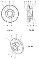
- FIG. 2 a shows a plan view of a first embodiment of the inventive spring-loaded nut, in a side view in FIG. 2 b, and in a three-dimensional view in FIG. 2 c.
- the spring-loaded nut comprises a cylindrical and polygonal cross-section formed edge element 1, which has a from a first end face 2 of the edge element 1 to a second end face 3 of the edge element 1 extending through hole 4.
- a disc element 5 is provided, which has a first end face 6 on the first end side 2 of the edge element 1 is arranged, wherein the disc element 5 protrudes on the first end face 2 of the edge element 1 and this projects beyond it.
- the polygonal cross section of the edge element 1 has at least three corners.
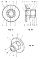
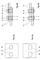
- FIG. 4b additionally shows a first embodiment and in FIG. 5b a second embodiment of an electrical busbar according to the invention, each in a side view.
- the inventive electrical busbar comprises a stack 13 of at least two at least partially covering busbar plates 14, wherein the stack 13 has at least one continuous hole 15 extending in the stacking direction and through the at least one through hole 15 of the stack 13, a screw 16 is guided.
- the screw end of the screw 16 for clamping the stack 13 is now screwed into the already described by way of example with reference to Fig. 2a, Fig. 2b and Fig.
- the inventive spring-loaded nut in the assembled state advantageously requires only a minimum of space. Furthermore, the assembly of the spring-loaded nut can be done very easily and quickly with advantage, since this must be inserted, for example, only with the Katenelement 1 in the through hole 15 of the stack 13 of the rail plates 14 in an electrical rail and then only the screw 16 in the continuous Passed hole 15 of the stack 13 and the end of the screw must be screwed into the spring counternut.
- the disk element 5 of the spring-loaded nut advantageously prevents slippage of the edge element 1 and thus the entire spring-loaded nut through the through hole 15 of the stack 13 during assembly and also serves to receive the stack pressing forces when tightening the screw 16.
- the electrical busbar can be particularly compact and space-saving realized as the edge element 1 in the through hole 15 of the stack 13 of the busbar plates Protrudes 14 and only the disc element 5 on the stack 13, in particular with respect to the stacking direction, protrudes.
- the edge element 1 protrudes into the through hole 15 of the stack 13 of the busbar plates 14, shorter screws 16 can continue to be used, thereby advantageously saving material can be and resulting in a lower weight of the overall electrical busbar results.
- the mounting of the inventive electrical busbar advantageously can be particularly simple and fast, because, as already mentioned above, the inventive spring nut must be inserted only with the Katenelement 1 in the through hole 15 of the stack 13 of the busbar plates 14 and then only the Screw 16 is guided in the through hole 15 of the stack 13 and the end of the screw must be screwed into the spring nut, the disc member 5 of the spring countersunk with advantage slipping of the edge element 1 and thus the whole spring counternut through the through hole 15 of the stack 13 during assembly prevented.
- the part of the disk element 5 which projects beyond the first end face 2 of the edge element 1 is preferably in the direction of the edge element 1, i. in the direction of the cylinder extension direction of the edge element 1, bent.
- a clamping force can be generated on the stack 13 of the screw head of the screw 16, which secures the screw 16 against unintentional twisting, loosening and loosening.
- the disc element 5 with the mentioned bend thus represents an extremely simple and efficient thread lock for the screw 16.
- a biasing force is generated in the stack 13 by the disc element 5 with the mentioned bend, which the stack 13 under changing operating conditions, for example in material expansions due to temperature differences, holds together securely.
- the disk element 5 according to FIGS. 2 a, 2b and 2c preferably has a through hole 8 running from the first end face 6 of the disk element 5 to a second end face 7 of the disk element 5, wherein the hole 8 of the disk element 5 is aligned with the one Hole 4 of the edge element 1 is arranged, so that thus a through hole is formed through the entire spring counternut.
- a through hole is formed through the entire spring counternut.
- the disc element 5 is not necessarily one from the first end side 6 of the disc element 5 to the second end face 7 of the disc element 5 must have running through hole 8, but also without a hole, ie in particular designed as a solid material disc element 5, can be performed.
- a second embodiment of the inventive spring-nut is shown in a plan view, in Fig. 3b in a side view and in Fig. 3c in a three-dimensional view.
- the spring counternut shown therein comprises a cylindrical extension element 9 of circular cross-section which is arranged with a first end face 10 on the second end face 3 of the edge element 1, the circular cross section of the extension element 9 is inscribed in the polygonal cross section of the edge element 1.
- the extension element 9 has a from the first end face 10 of the extension element 9 to a second end face 11 of the extension element 9 extending through hole 12, wherein the hole 12 of the extension element 9 is arranged in alignment with the hole 4 of the edge element 1.
- the extension element 9 serves the improved guidance of the spring-loaded nut during its assembly, for example, in an electrical rail, in particular when inserted into the through hole 15 of the stack 13 of the rail plates 14.
- Fig. 5b shows the already mentioned second embodiment of the inventive electrical busbar in a Side view with Federsenkmuttern according to Fig. 3a, Fig. 3b and Fig. 3c.
- extension element 9 Another advantage of the extension element 9 is that the installation of the electrical busbar can be greatly simplified, since, in particular at a suitable length of the extension element 9, for example in a stack 13 of two busbar plates 14 at least one busbar plate 14 can be temporarily held in position until the associated screw 16 is inserted into the through hole 15 of the stack 13, screwed into the spring counternut and finally tightened. A holding device or additional staff for holding the at least one bus plate 14 in its mounting position is thereby unnecessary.
- the hole 4 of the edge element 1 the hole 8 of the disk element 5 and the hole 12 of the extension element 9 each have an internal thread.
- any other combination is conceivable that, for example, only the Hole 8 of the disc member 5 or only the hole 12 of the extension member 9 has an internal thread etc.
- the edge element 1 preferably forms a piece with the extension element 9. Furthermore, with regard to the embodiments of the spring-loaded nut according to FIGS. 2 a, 2b, 2c, 3a, 3b or 3c, it is also conceivable that the edge element 1 forms a piece with the disk element 5, wherein it However, with respect to the embodiments of the spring-loaded nut according to FIG. 3 a, 3 b or 3 c, it would also be possible for the edge element 1 to form a piece with the disk element 5 and with the extension element 9.
- the one-piece result in improved strength of the spring-loaded nut and a simplified manufacture of the spring-loaded nut, for example by casting and / or forging.
- a first embodiment of the busbar plate 14 of the inventive electrical busbar is shown in a plan view.
- Fig. 5a shows a second embodiment of the busbar plate 14 of the inventive electrical busbar in a plan view.
- the hole of the busbar plate 14 shown by way of example in FIG. 4a and FIG. 5a and thus the through hole 15 of the stack 13 of the busbar plates 14 has a hole wall surface 18 with at least two planar surface parts. It should be understood that the perforated wall surface 18 of the through hole 15 of the stack 13, besides the at least two planar surface portions, would otherwise be generally of any shape, e.g. may have additional surface parts of any shape.
- the edge element 1 is preferably in contact with at least two side surfaces 17 of the edge element 1 on the hole wall surface 18 of the at least one through hole 15 of the stack 14.
- the screw 16 is formed as a countersunk screw and thus protrudes with its screw head into the through hole 15 of the stack 13 and thus not or only slightly above the Stack 13 protrudes.
- Fig. 6 is exemplified a third embodiment of the inventive electrical busbar with such a countersunk screw, in particular with bevelled Screw head surface, shown. It is understood that when using such a kind of countersunk screw parts of the inner hole surface 18 of the through hole 15 of the stack 13 should be formed for receiving the screw head of the countersunk screw.
Abstract
Description
Die Erfindung bezieht sich auf das Gebiet der Befestigungstechnik. Sie geht aus von einer Federsenkmutter sowie von einer elektrischen Verschienung mit einer solchen Federsenkmutter gemäss den Oberbegriffen der unabhängigen Ansprüche.The invention relates to the field of fastening technology. It is based on a spring-loaded nut and an electrical busbar with such a spring nut according to the preambles of the independent claims.
Elektrische Verschienungen, insbesondere in leistungselektronischen Anwendungen wie Umrichtern, umfassen gängigerweise einen Stapel aus mindestens zwei sich zumindest teilweise überdeckenden Verschienungsplatten, wobei der Stapel mindestens ein in Stapelrichtung verlaufendes durchgehendes, insbesondere kreisförmiges, Loch aufweist und durch das mindestens eine durchgehende Loch des Stapels eine Schraube geführt ist, insbesondere wie in einer Ausführungsform nach dem Stand der Technik gemäss Fig. 1 gezeigt. Auf das Schraubenende ist üblicherweise eine gängige Mutter aufgedreht, so dass die Verschienungsplatten in ihrem Überdeckungsbereich gegeneinander gepresst werden. Die Mutter umfasst typischerweise ein zylinderförmiges und mit polygonalem Querschnitt ausgebildetes Kantenelement, welches ein von einer ersten Stirnseite des Kantenelementes zu einer zweiten Stirnseite des Kantenelementes verlaufendes durchgehendes Loch aufweist, wobei das Loch des Kantenelementes ein Innengewinde aufweist, welches insbesondere zu der vorstehend genannten Schraube passt.Electrical busbars, in particular in power electronic applications such as converters, conventionally comprise a stack of at least two busbar plates at least partially overlapping, wherein the stack has at least one continuous, in particular circular, hole extending in the stacking direction and guides one screw through the at least one through hole of the stack is, in particular as shown in an embodiment of the prior art according to FIG. 1. On the end of the screw usually a common nut is turned on, so that the busbar plates are pressed against each other in their coverage area. The mother typically comprises a cylindrical and formed with polygonal cross-section edge element, which has a from a first end side of the edge element to a second end side of the edge element extending through hole, wherein the hole of the edge element has an internal thread which fits in particular to the above-mentioned screw.
Problematisch bei einer elektrischen Verschienung nach dem Stand der Technik gemäss Fig. 1 ist, dass die Mutter aufgrund ihre Bauhöhe deutlich über den Stapel der Verschienungsplatten hinausragt und demnach sehr viel Platz beansprucht. Zudem muss jeweils eine lange Schraube verwendet werden, damit die Mutter überhaupt ausreichend angezogen werden kann, wodurch ein erhöhter Materialaufwand notwendig ist und sich das Gewicht erhöht. Ferner muss die jeweilige Mutter bei der Montage bis zum Aufdrehen auf das Schraubenende festgehalten werden und bei der Aufdrehung auf das Schraubenende zusätzlich bezüglich Verdrehung, beispielsweise durch Gegenhalten mittels eines Werkzeugs, gesichert werden, wodurch sich ein erheblicher Montageaufwand, Personalaufwand und Zeitaufwand ergibt.The problem with an electrical busbar according to the prior art according to FIG. 1 is that the mother protrudes significantly beyond the stack of busbar panels due to their height and therefore requires a great deal of space. In addition, a long screw must be used so that the mother can ever be sufficiently attracted, whereby an increased cost of materials is necessary and increases the weight. Furthermore, the respective nut must be held in the assembly until it is screwed on the end of the screw and additionally secured in rotation on the end of the screw with respect to rotation, for example by holding with a tool, resulting in a considerable installation effort, labor and time.
Aufgabe der Erfindung ist es deshalb, eine Mutter, insbesondere eine Federsenkmutter, anzugeben, welche im montierten Zustand wenig Platz beansprucht und einfach und schnell montiert werden kann. Ferner ist es eine Aufgabe der Erfindung, eine elektrische Verschienung mit einer solchen Federsenkmutter bereitzustellen, welche wenig Platz benötigt, einen geringen Materialaufwand und ein geringes Gewicht aufweist und einfach und schnell realisiert werden kann. Diese Aufgaben werden durch die Merkmale der unabhängigen Ansprüche gelöst. In den abhängigen Ansprüchen sind vorteilhafte Weiterbildungen der Erfindung angegeben.The object of the invention is therefore to provide a nut, in particular a spring-loaded nut, which requires little space in the assembled state and can be easily and quickly mounted. Furthermore, it is an object of the invention to provide an electrical rail with such a spring-loaded nut, which requires little space, has a low material cost and low weight and can be easily and quickly realized. These objects are achieved by the features of the independent claims. In the dependent claims advantageous developments of the invention are given.
Die erfindungsgemässe Federsenkmutter umfasst ein zylinderförmiges und mit polygonalem Querschnitt ausgebildetes Kantenelement, welches ein von einer ersten Stirnseite des Kantenelementes zu einer zweiten Stirnseite des Kantenelementes verlaufendes durchgehendes Loch aufweist. Nach der Erfindung ist ein Scheibenelement vorgesehen, welches mit einer ersten Stirnseite an der ersten Stirnseite des Kantenelementes angeordnet ist, wobei das Scheibenelement an der ersten Stirnseite des Kantenelementes übersteht. Ferner umfasst die erfindungsgemässe elektrische Verschienung einen Stapel aus mindestens zwei sich zumindest teilweise überdeckenden Verschienungsplatten, wobei der Stapel mindestens ein in Stapelrichtung verlaufendes durchgehendes Loch aufweist und durch das mindestens eine durchgehende Loch des Stapels eine Schraube geführt ist. Erfindungsgemäss ist das Schraubenende der Schraube zur Verspannung des Stapels nun in die vorstehend genannte Federsenkmutter nach der Erfindung eingedreht, wobei das Kantenelement in das durchgehende Loch des Stapels hineinragt. Damit beansprucht die erfindungsgemässe Federsenkmutter im montierten Zustand vorteilhaft nur sehr wenig Platz. Ferner kann die Montage der Federsenkmutter mit Vorteil sehr einfach und schnell erfolgen, da diese beispielsweise bei einer elektrischen Verschienung lediglich mit dem Katenelement in das durchgehende Loch des Stapels der Verschienungsplatten eingelegt werden muss und danach nur noch die Schraube in das durchgehende Loch des Stapels geführt und das Schraubenende in die Federsenkmutter eingedreht werden muss. Das Scheibenelement der Federsenkmutter verhindert mit Vorteil ein Durchrutschen des Kantenelementes und damit der ganzen Federsenkmutter durch das durchgehende Loch des Stapels bei der Montage und dient ferner der Aufnahme der Stapelpresskräfte beim Festziehen der Schraube. Mittels der bei der erfindungsgemässen elektrischen Verschienung verwendeten erfindungsgemässen Federsenkmutter kann die elektrische Verschienung besonders kompakt und platzsparend realisiert werden, da das Kantenelement in das durchgehende Loch des Stapels der Verschienungsplatten hineinragt und lediglich das Scheibenelement über den Stapel übersteht. Die erfindungsgemässe elektrische Verschienung ist damit besonders für leistungselektronische Anwendungen, beispielsweise für Traktionsanwendungen, interessant, bei welchen normalerweise sehr eingeschränkte Platzverhältnisse vorherrschen. Dadurch, dass das Kantenelement in das durchgehende Loch des Stapels der Verschienungsplatten hineinragt, können weiterhin kürzere Schrauben verwendet werden, wodurch vorteilhaft Material eingespart werden kann und woraus ein geringeres Gewicht der elektrischen Verschienung folgt. Darüber hinaus kann die Montage der erfindungsgemässen elektrischen Verschienung vorteilhaft besonders einfach und schnell erfolgen, da, wie bereits vorstehend erwähnt, die erfindungsgemässe Federsenkmutter lediglich mit dem Katenelement in das durchgehende Loch des Stapels der Verschienungsplatten eingelegt werden muss und danach nur noch die Schraube in das durchgehende Loch des Stapels geführt und das Schraubenende in die Federsenkmutter eingedreht werden muss, wobei das Scheibenelement der Federsenkmutter mit Vorteil ein Durchrutschen des Kantenelementes und damit der ganzen Federsenkmutter durch das durchgehende Loch des Stapels bei der Montage verhindert.The inventive spring countersunk nut comprises a cylindrical and formed with a polygonal cross-section edge element, which has a running from a first end side of the edge element to a second end side of the edge element through hole. According to the invention, a disc element is provided, which is arranged with a first end face on the first end side of the edge element, wherein the Disc element protrudes at the first end side of the edge element. Furthermore, the electrical busbar according to the invention comprises a stack of at least two busbar plates at least partially overlapping, the stack having at least one through hole extending in the stacking direction and a screw passing through the at least one through hole of the stack. According to the invention, the screw end of the screw for clamping the stack is now screwed into the abovementioned spring-loaded nut according to the invention, wherein the edge element protrudes into the through hole of the stack. Thus, the inventive spring countersunk nut claimed in the assembled state advantageously only very little space. Furthermore, the assembly of the spring-loaded nut can be done very easily and quickly with advantage, as this must be inserted, for example, only with the catenary element in the through hole of the stack of busbar panels at an electrical railing and then guided only the screw in the through hole of the stack and the screw end must be screwed into the spring counternut. The disc element of the spring-loaded nut advantageously prevents slippage of the edge element and thus of the entire spring-loaded nut through the through hole of the stack during assembly and also serves to receive the stack pressing forces when tightening the screw. By means of the novel spring counternut according to the invention used in the electrical busbar, the electrical busbar can be realized in a particularly compact and space-saving manner, since the edge element protrudes into the through hole of the stack of busbar plates and only projects beyond the stack. The electrical busbar system according to the invention is therefore of particular interest for power electronic applications, for example for traction applications, in which normally very limited space conditions prevail. The fact that the edge element protrudes into the through hole of the stack of busbar plates, moreover, shorter screws can be used, which advantageously material can be saved and from which a lower weight of the electrical busbar follows. In addition, the mounting of the inventive electrical busbar advantageously can be particularly simple and fast, since, as already mentioned above, the inventive spring nut must be inserted only with the Katenelement in the through hole of the stack of busbar panels and then only the screw in the continuous Passed hole of the stack and the screw end must be screwed into the spring counternut, the disc element of the spring countersunk with advantage slipping the edge element and thus the entire spring-loaded nut prevented by the through hole of the stack during assembly.
Diese und weitere Aufgaben, Vorteile und Merkmale der vorliegenden Erfindung werden aus der nachfolgenden detaillierten Beschreibung bevorzugter Ausführungsformen der Erfindung in Verbindung mit der Zeichnung offensichtlich.These and other objects, advantages and features of the present invention will become more apparent from the following detailed description of preferred embodiments of the invention taken in conjunction with the accompanying drawings.
Es zeigen:
- Fig. 1
- eine Ausführungsform einer elektrischen Verschienung nach dem Stand der Technik,
- Fig. 2a
- eine erste Ausführungsform der erfindungsgemässen Federsenkmutter in einer Aufsicht,
- Fig. 2b
- die erste Ausführungsform der erfindungsgemässen Federsenkmutter in einer Seitenansicht,
- Fig. 2c
- die erste Ausführungsform der erfindungsgemässen Federsenkmutter in einer räumlichen Ansicht,
- Fig. 3a
- eine zweite Ausführungsform der erfindungsgemässen Federsenkmutter in einer Aufsicht,
- Fig. 3b
- die zweite Ausführungsform der erfindungsgemässen Federsenkmutter in einer Seitenansicht,
- Fig. 3c
- die zweite Ausführungsform der erfindungsgemässen Federsenkmutter in einer räumlichen Ansicht,
- Fig. 4a
- eine erste Ausführungsform einer Verschienungsplatte einer erfindungsgemässen elektrischen Verschienung in einer Aufsicht,
- Fig. 4b
- eine erste Ausführungsform einer erfindungsgemässen elektrischen Verschienung, insbesondere mit einer Verschienungsplatte nach Fig. 4a, in einer Seitenansicht,
- Fig. 5a
- eine zweite Ausführungsform einer Verschienungsplatte einer erfindungsgemässen elektrischen Verschienung in einer Aufsicht,
- Fig. 5b
- eine zweite Ausführungsform einer erfindungsgemässen elektrischen Verschienung, insbesondere mit einer Verschienungsplatte nach Fig. 5a, in einer Seitenansicht und
- Fig. 6
- eine dritte Ausführungsform einer erfindungsgemässen elektrischen Verschienung.
- Fig. 1
- an embodiment of an electrical rail according to the prior art,
- Fig. 2a
- A first embodiment of the inventive spring-loaded nut in a plan view,
- Fig. 2b
- the first embodiment of the inventive spring-loaded nut in a side view,
- Fig. 2c
- the first embodiment of the inventive spring-loaded nut in a three-dimensional view,
- Fig. 3a
- A second embodiment of the inventive spring-loaded nut in a plan view,
- Fig. 3b
- the second embodiment of the inventive spring nut in a side view,
- Fig. 3c
- the second embodiment of the inventive spring-loaded nut in a three-dimensional view,
- Fig. 4a
- a first embodiment of a busbar plate of an inventive electrical busbar in a plan view,
- Fig. 4b
- 1 shows a first embodiment of an inventive electrical busbar, in particular with a busbar plate according to FIG. 4a, in a side view,
- Fig. 5a
- A second embodiment of a busbar plate of an inventive electrical busbar in a plan view,
- Fig. 5b
- a second embodiment of an inventive electrical busbar, in particular with a busbar plate according to Fig. 5a, in a side view and
- Fig. 6
- A third embodiment of an inventive electrical busbar.
Die in der Zeichnung verwendeten Bezugszeichen und deren Bedeutung sind in der Bezugszeichenliste zusammengefasst aufgelistet. Grundsätzlich sind in den Figuren gleiche Teile mit gleichen Bezugszeichen versehen. Die beschriebenen Ausführungsformen stehen beispielhaft für den Erfindungsgegenstand und haben keine beschränkende Wirkung.The reference numerals used in the drawings and their meaning are listed in the list of reference numerals. Basically, the same parts are provided with the same reference numerals in the figures. The described embodiments are exemplary of the subject invention and have no limiting effect.
In Fig. 2a ist eine erste Ausführungsform der erfindungsgemässen Federsenkmutter in einer Aufsicht, in Fig. 2b in einer Seitenansicht und in Fig. 2c in einer räumlichen Ansicht dargestellt. Gemäss dieser ersten Ausführungsform umfasst die Federsenkmutter ein zylinderförmiges und mit polygonalem Querschnitt ausgebildetes Kantenelement 1, welches ein von einer ersten Stirnseite 2 des Kantenelementes 1 zu einer zweiten Stirnseite 3 des Kantenelementes 1 verlaufendes durchgehendes Loch 4 aufweist. Erfindungsgemäss ist ein Scheibenelement 5 vorgesehen, welches mit einer ersten Stirnseite 6 an der ersten Stirnseite 2 des Kantenelementes 1 angeordnet ist, wobei das Scheibenelement 5 an der ersten Stirnseite 2 des Kantenelementes 1 übersteht und diese damit überragt. Vorzugsweise weist der polygonale Querschnitt des Kantenelementes 1 mindestens drei Ecken auf.FIG. 2 a shows a plan view of a first embodiment of the inventive spring-loaded nut, in a side view in FIG. 2 b, and in a three-dimensional view in FIG. 2 c. According to this first embodiment, the spring-loaded nut comprises a cylindrical and polygonal cross-section formed
In Fig. 4b ist zudem eine erste Ausführungsform und in Fig. 5b eine zweite Ausführungsform einer erfindungsgemässen elektrischen Verschienung jeweils in einer Seitenansicht gezeigt. Die erfindungsgemässe elektrische Verschienung umfasst einen Stapel 13 aus mindestens zwei sich zumindest teilweise überdeckenden Verschienungsplatten 14, wobei der Stapel 13 mindestens ein in Stapelrichtung verlaufendes durchgehendes Loch 15 aufweist und durch das mindestens eine durchgehende Loch 15 des Stapels 13 eine Schraube 16 geführt ist. Erfindungsgemäss ist das Schraubenende der Schraube 16 zur Verspannung des Stapels 13 nun in die vorstehend anhand von Fig. 2a, Fig. 2b und Fig. 2c bereits beispielhaft beschriebene Federsenkmutter nach der Erfindung eingedreht, wobei das Kantenelement 1 in das durchgehende Loch 15 des Stapels hineinragt. Damit benötigt die erfindungsgemässe Federsenkmutter im montierten Zustand vorteilhaft nur ein Minimum an Platz. Ferner kann die Montage der Federsenkmutter mit Vorteil sehr einfach und schnell erfolgen, da diese beispielsweise bei einer elektrischen Verschienung lediglich mit dem Katenelement 1 in das durchgehende Loch 15 des Stapels 13 der Verschienungsplatten 14 eingelegt werden muss und danach nur noch die Schraube 16 in das durchgehende Loch 15 des Stapels 13 geführt und das Schraubenende in die Federsenkmutter eingedreht werden muss. Das Scheibenelement 5 der Federsenkmutter verhindert vorteilhaft ein Durchrutschen des Kantenelementes 1 und damit der ganzen Federsenkmutter durch das durchgehende Loch 15 des Stapels 13 bei der Montage und dient ferner der Aufnahme der Stapelpresskräfte beim Festziehen der Schraube16.FIG. 4b additionally shows a first embodiment and in FIG. 5b a second embodiment of an electrical busbar according to the invention, each in a side view. The inventive electrical busbar comprises a
Mittels der bei der erfindungsgemässen elektrischen Verschienung, welche vorstehend anhand von Fig. 4b und Fig. 5b beschrieben wurde, verwendeten erfindungsgemässen Federsenkmutter kann die elektrische Verschienung besonders kompakt und platzsparend realisiert werden, da das Kantenelement 1 in das durchgehende Loch 15 des Stapels 13 der Verschienungsplatten 14 hineinragt und lediglich das Scheibenelement 5 über den Stapel 13 , insbesondere bezüglich der Stapelrichtung, übersteht. Dadurch, dass das Kantenelement 1 in das durchgehende Loch 15 des Stapels 13 der Verschienungsplatten 14 hineinragt, können weiterhin kürzere Schrauben 16 verwendet werden, wodurch vorteilhaft Material eingespart werden kann und woraus ein geringeres Gewicht der elektrischen Verschienung insgesamt resultiert. Darüber hinaus kann die Montage der erfindungsgemässen elektrischen Verschienung vorteilhaft besonders einfach und schnell erfolgen, da, wie bereits vorstehend erwähnt, die erfindungsgemässe Federsenkmutter lediglich mit dem Katenelement 1 in das durchgehende Loch 15 des Stapels 13 der Verschienungsplatten 14 eingelegt werden muss und danach nur noch die Schraube 16 in das durchgehende Loch 15 des Stapels 13 geführt und das Schraubenende in die Federsenkmutter eingedreht werden muss, wobei das Scheibenelement 5 der Federsenkmutter mit Vorteil ein Durchrutschen des Kantenelementes 1 und damit der ganzen Federsenkmutter durch das durchgehende Loch 15 des Stapels 13 bei der Montage verhindert.By means of the invention in the inventive electrical busbar, which was described above with reference to Fig. 4b and Fig. 5b, used spring-nut, the electrical busbar can be particularly compact and space-saving realized as the
Gemäss Fig. 2b ist der bezüglich der ersten Stirnseite 2 des Kantenelementes 1 überstehende Teil des Scheibenelementes 5 vorzugsweise in Richtung des Kantenelementes 1, d.h. in Richtung der Zylindererstreckungsrichtung des Kantenelementes 1, gebogen. Bei der Montage der Federsenkmutter, beispielsweise für die erfindungsgemässe elektrischen Verschienung, insbesondere nach Fig. 4b bzw. Fig. 5b, kann dadurch beim Festziehen der Schraube 16 eine Spannkraft auf den sich auf den Stapel 13 abstützenden Teil des Schraubenkopfes der Schraube 16 erzeugt werden, welche die Schraube 16 gegen ungewolltes Verdrehen, Aufdrehen und Lösen sichert. Das Scheibenelement 5 mit der erwähnten Biegung stellt somit eine äusserst einfache und effiziente Schraubensicherung für die Schraube 16 dar. Zudem wird durch das Scheibenelement 5 mit der erwähnten Biegung eine Vorspannkraft im Stapel 13 erzeugt, welche den Stapel 13 bei sich ändernden Betriebsbedingungen, beispielsweise bei Materialausdehnungen infolge von Temperaturunterschieden, sicher zusammenhält.According to FIG. 2 b, the part of the
Vorzugsweise weist das Scheibenelement 5 gemäss Fig. 2a, Fig. 2b und Fig. 2c ein von der ersten Stirnseite 6 des Scheibenelementes 5 zu einer zweiten Stirnseite 7 des Scheibenelementes 5 verlaufendes durchgehendes Loch 8 auf, wobei das Loch 8 des Scheibenelementes 5 fluchtend zu dem Loch 4 des Kantenelementes 1 angeordnet, so dass damit ein durchgehendes Loch durch die gesamte Federsenkmutter gebildet ist. Falls z.B. nur längere Schrauben, d.h. wesentlich grösser als die Stapelhöhe des Stapels 13, bei der Montage verfügbar sind, können auch solche Schrauben verwendet werden, welche dann im montierten Zustand über das Loch 8 des Scheibenelementes 5 hinausragen. In diesem Zusammenhang sei erwähnt, dass das Scheibenelement 5 nicht notwendigerweise ein von der ersten Stirnseite 6 des Scheibenelementes 5 zur zweiten Stirnseite 7 des Scheibenelementes 5 verlaufendes durchgehendes Loch 8 aufweisen muss, sondern auch ohne Loch, d.h. insbesondere als Vollmaterial ausgebildetes Scheibenelement 5, ausgeführt sein kann.The
In Fig. 3a ist eine zweite Ausführungsform der erfindungsgemässen Federsenkmutter in einer Aufsicht, in Fig. 3b in einer Seitenansicht und in Fig. 3c in einer räumlichen Ansicht gezeigt. Die darin dargestellte Federsenkmutter umfasst im Unterschied zu Fig. 2a, Fig. 2b und Fig. 2c ein zylinderförmiges und mit kreisförmigem Querschnitt ausgebildetes Verlängerungselement 9, welches mit einer ersten Stirnseite 10 an der zweiten Stirnseite 3 des Kantenelementes 1 angeordnet ist, wobei der kreisförmige Querschnitt des Verlängerungselementes 9 dem polygonalen Querschnitt des Kantenelementes 1 einbeschrieben ist. Zudem weist das Verlängerungselement 9 ein von der ersten Stirnseite 10 des Verlängerungselementes 9 zu einer zweiten Stirnseite 11 des Verlängerungselementes 9 verlaufendes durchgehendes Loch 12 auf, wobei das Loch 12 des Verlängerungselementes 9 fluchtend zu dem Loch 4 des Kantenelementes 1 angeordnet. Vorteilhaft dient das Verlängerungselement 9 der verbesserten Führung der Federsenkmutter bei deren Montage beispielsweise bei einer elektrischen Verschienung, insbesondere beim Einlegen in das durchgehende Loch 15 des Stapels 13 der Verschienungsplatten 14. Fig. 5b zeigt dazu die bereits erwähnte zweite Ausführungsform der erfindungsgemässen elektrischen Verschienung in einer Seitenansicht mit Federsenkmuttern nach Fig. 3a, Fig. 3b bzw. Fig. 3c. Ein weiterer Vorteil des Verlängerungselementes 9 besteht darin, dass sich die Montage der elektrischen Verschienung stark vereinfachen lässt, da, insbesondere bei einer geeigneten Länge des Verlängerungselementes 9, beispielsweise bei einem Stapel 13 aus zwei Verschienungsplatten 14 mindestens eine Verschienungsplatte 14 temporär in Position gehalten werden kann, bis die zugehörige Schraube 16 in das durchgehende Loch 15 des Stapels 13 eingeführt, in die Federsenkmutter eingedreht und schlussendlich festgezogen ist. Ein Haltevorrichtung oder zusätzliches Personal zum Halten der mindestens einen Verschienungsplatte 14 in ihrer Montageposition wird dadurch überflüssig.In Fig. 3a, a second embodiment of the inventive spring-nut is shown in a plan view, in Fig. 3b in a side view and in Fig. 3c in a three-dimensional view. In contrast to FIGS. 2 a, 2b and 2c, the spring counternut shown therein comprises a
Bezüglich den Ausführungsformen der Federsenkmutter nach Fig. 2a, Fig. 2b, Fig. 2c, Fig. 3a, Fig. 3b bzw. Fig. 3c kann das Loch 4 des Kantenelementes 1, das Loch 8 des Scheibenelementes 5 und das Loch 12 des Verlängerungselementes 9 jeweils ein Innengewinde aufweisen. Für den Fachmann ist aber jegliche andere Kombination denkbar, dass z.B. nur das Loch 8 des Scheibenelementes 5 oder nur das das Loch 12 des Verlängerungselementes 9 ein Innengewinde etc. aufweist.With regard to the embodiments of the spring-loaded nut according to FIGS. 2 a, 2b, 2c, 3a, 3b and 3c, the
Bezüglich den Ausführungsformen der Federsenkmutter nach Fig. 3a, Fig. 3b bzw. Fig. 3c bildet das Kantenelement 1 mit dem Verlängerungselement 9 vorzugsweise ein Stück. Ferner ist es bezüglich den Ausführungsformen der Federsenkmutter nach Fig. 2a, Fig. 2b, Fig. 2c, Fig. 3a, Fig. 3b bzw. Fig. 3c auch denkbar, dass das Kantenelement 1 mit dem Scheibenelement 5 ein Stück bildet, wobei es aber bezüglich den Ausführungsformen der Federsenkmutter nach Fig. 3a, Fig. 3b bzw. Fig. 3c auch möglich wäre, dass das Kantenelement 1 mit dem Scheibenelement 5 und mit dem Verlängerungselement 9 ein Stück bildet. Durch die Einstückigkeit ergibt sich eine verbesserte Festigkeit der Federsenkmutter und eine vereinfachte Fertigung der Federsenkmutter, beispielsweise durch Giessen und/oder Schmieden.With regard to the embodiments of the spring-loaded nut according to FIG. 3 a, 3 b or 3 c, the
In Fig. 4a ist eine erste Ausführungsform der Verschienungsplatte 14 der erfindungsgemässen elektrischen Verschienung in einer Aufsicht dargestellt. Desweiteren zeigt Fig. 5a eine zweite Ausführungsform der Verschienungsplatte 14 der erfindungsgemässen elektrischen Verschienung in einer Aufsicht. Allgemein weist das in Fig. 4a und Fig. 5a beispielhaft gezeigte Loch der Verschienungsplatte 14 und damit das durchgehende Loch 15 des Stapels 13 der Verschienungsplatten 14 eine Lochwandfläche 18 mit mindestens zwei ebenen Flächenteilen auf. Es versteht sich, dass die Lochwandfläche 18 des durchgehenden Loches 15 des Stapels 13 neben den mindestens zwei ebenen Flächenteilen ansonsten allgemein jedwede Form, d.h. zusätzliche Flächenteile jeglicher Form aufweisen kann. Damit die Federsenkmutter im montierten Zustand der erfindungsgemässen elektrischen Verschienung vorteilhaft gegen Lösen gesichert ist, liegt das Kantenelement 1 vorzugsweise mit mindestens zwei Seitenflächen 17 des Kantenelementes 1 an der Lochwandfläche 18 des mindestens einen durchgehenden Loches 15 des Stapels 14 an.In Fig. 4a, a first embodiment of the
Zur Reduzierung der Bauhöhe der erfindungsgemässen elektrischen Verschienung und damit zur weiteren Platzeinsparung hat es sich als vorteilhaft erwiesen, dass die Schraube 16 als Senkschraube ausgebildet ist und damit mit ihrem Schraubenkopf in das durchgehende Loch 15 des Stapels 13 hineinragt und somit nicht oder nur unwesentlich über den Stapel 13 hinausragt. In Fig. 6 ist dazu beispielhaft eine dritte Ausführungsform der erfindungsgemässen elektrischen Verschienung mit einer solchen Senkschraube, insbesondere mit abgeschrägter Schraubenkopffläche, gezeigt. Es versteht sich, dass bei Verwendung einer solch gearteten Senkschraube Teile der Lochinnenfläche 18 des durchgehenden Loches 15 des Stapels 13 zur Aufnahme des Schraubenkopfes der Senkschraube ausgebildet sein sollten.To reduce the height of the inventive electrical busbar and thus to further space savings, it has proven to be advantageous that the
- 11
- Kantenelementedge element
- 22
- erste Stirnseite des Kanteelementesfirst end face of the edge element
- 33
- zweite Stirnseite des Kanteelementessecond end face of the edge element
- 44
- durchgehendes Loch des Kantenelementesthrough hole of the edge element
- 55
- Scheibenelementdisk element
- 66
- erste Stirnseite des Scheibenelementesfirst end face of the disc element
- 77
- zweite Stirnseite des Scheibenelementessecond end face of the disc element
- 88th
- durchgehendes Loch des Scheibenelementesthrough hole of the disc element
- 99
- Verlängerungselementextension element
- 1010
- erste Stirnseite des Verlängerungselementesfirst end face of the extension element
- 1111
- zweite Stirnseite des Verlängerungselementessecond end face of the extension element
- 1212
- durchgehendes Loch des Verlängerungselementesthrough hole of the extension element
- 1313
- Stapel aus VerschienungsplattenStack of busbar panels
- 1414
- VerschienungsplattenBusbar panels
- 1515
- durchgehendes Loch des Stapelsthrough hole of the pile
- 1616
- Schraubescrew
- 1717
- Seitenfläche des KantenelementesSide surface of the edge element
- 1818
- Lochwandfläche des durchgehenden Loches des StapelsHole wall surface of the through hole of the stack
Claims (13)
dadurch gekennzeichnet,
dass ein Scheibenelement (5) vorgesehen ist, welches mit einer ersten Stirnseite (6) an der ersten Stirnseite (2) des Kantenelementes (1) angeordnet ist, und
dass das Scheibenelement 5() an der ersten Stirnseite (1) des Kantenelementes () übersteht.Spring-loaded nut having a cylindrical edge element (1) formed with a polygonal cross section and having a through hole (4) running from a first end face (2) of the edge element (1) to a second end face (3) of the edge element (1),
characterized,
that a disc element (5) is provided, which with a first end face (6) on the first end side (2) of the edge element (1) is arranged, and
in that the disk element 5 (12) projects beyond the first end face (1) of the edge element (12).
dass das Verlängerungselement (9) ein von der ersten Stirnseite (10) des Verlängerungselementes (9) zu einer zweiten Stirnseite (11) des Verlängerungselementes (9) verlaufendes durchgehendes Loch (12) aufweist, wobei das Loch (12) des Verlängerungselementes (9) fluchtend zu dem Loch (4) des Kantenelementes (1) angeordnet.Spring nut according to one of claims 1 to 3, characterized in that a cylindrical and formed with a circular cross-section extension element (9) is provided which is arranged with a first end face (10) on the second end face (3) of the edge element (1), wherein the circular cross section of the extension element (9) is inscribed in the polygonal cross section of the edge element (1), and
in that the extension element (9) has a through hole (12) extending from the first end face (10) of the extension element (9) to a second end face (11) of the extension element (9), the hole (12) of the extension element (9) aligned with the hole (4) of the edge element (1).
dadurch gekennzeichnet,
dass das Schraubenende der Schraube (16) zur Verspannung des Stapels in eine Federsenkmutter nach einem der Ansprüche 1 bis 10 eingedreht ist, wobei das Kantenelement (1) in das durchgehende Loch (15) des Stapels (13) hineinragt.Electric busbar with a stack (13) comprising at least two busbar plates (14) at least partially overlapping, the stack (13) having at least one through hole (15) running in the stacking direction and passing through the at least one through hole (15) of the stack ( 13) a screw (16) is guided,
characterized,
that the screw end of the screw (16) for bracing the stack is screwed into a Federsenkmutter according to any one of claims 1 to 10, wherein protrudes the edge element (1) in the through hole (15) of the stack (13).
Priority Applications (1)
| Application Number | Priority Date | Filing Date | Title |
|---|---|---|---|
| EP06405222A EP1860334A1 (en) | 2006-05-23 | 2006-05-23 | Countersunk spring nut device and electrical connection with such a device |
Applications Claiming Priority (1)
| Application Number | Priority Date | Filing Date | Title |
|---|---|---|---|
| EP06405222A EP1860334A1 (en) | 2006-05-23 | 2006-05-23 | Countersunk spring nut device and electrical connection with such a device |
Publications (1)
| Publication Number | Publication Date |
|---|---|
| EP1860334A1 true EP1860334A1 (en) | 2007-11-28 |
Family
ID=36968752
Family Applications (1)
| Application Number | Title | Priority Date | Filing Date |
|---|---|---|---|
| EP06405222A Withdrawn EP1860334A1 (en) | 2006-05-23 | 2006-05-23 | Countersunk spring nut device and electrical connection with such a device |
Country Status (1)
| Country | Link |
|---|---|
| EP (1) | EP1860334A1 (en) |
Cited By (3)
| Publication number | Priority date | Publication date | Assignee | Title |
|---|---|---|---|---|
| EP2642136A1 (en) * | 2012-03-19 | 2013-09-25 | Alstom Technology Ltd | Coupling structure and method to connect coupling parts |
| WO2016051035A1 (en) * | 2014-10-02 | 2016-04-07 | Peugeot Citroen Automobiles Sa | Vehicle axle hub having nuts with an elastic reserve for securing a disc wheel to substantially planar zones for bolts to pass through |
| US11152830B2 (en) * | 2019-01-28 | 2021-10-19 | Siemens Energy, Inc. | Isolated bolting connection for a generator |
Citations (5)
| Publication number | Priority date | Publication date | Assignee | Title |
|---|---|---|---|---|
| FR616097A (en) * | 1926-06-11 | 1927-01-22 | Improvements in bolts and their nuts | |
| GB683868A (en) * | 1950-05-05 | 1952-12-03 | United Carr Fastener Corp | Improvements in and relating to flanged nut assemblies |
| US4293256A (en) * | 1979-11-09 | 1981-10-06 | The Lamson & Sessions Co. | Load indicating fastener |
| US4671583A (en) * | 1983-02-24 | 1987-06-09 | The Boeing Company | Fastening device and method for composite structures |
| US6027293A (en) * | 1999-01-15 | 2000-02-22 | Deere & Company | Nut retaining plate |
-
2006
- 2006-05-23 EP EP06405222A patent/EP1860334A1/en not_active Withdrawn
Patent Citations (5)
| Publication number | Priority date | Publication date | Assignee | Title |
|---|---|---|---|---|
| FR616097A (en) * | 1926-06-11 | 1927-01-22 | Improvements in bolts and their nuts | |
| GB683868A (en) * | 1950-05-05 | 1952-12-03 | United Carr Fastener Corp | Improvements in and relating to flanged nut assemblies |
| US4293256A (en) * | 1979-11-09 | 1981-10-06 | The Lamson & Sessions Co. | Load indicating fastener |
| US4671583A (en) * | 1983-02-24 | 1987-06-09 | The Boeing Company | Fastening device and method for composite structures |
| US6027293A (en) * | 1999-01-15 | 2000-02-22 | Deere & Company | Nut retaining plate |
Cited By (4)
| Publication number | Priority date | Publication date | Assignee | Title |
|---|---|---|---|---|
| EP2642136A1 (en) * | 2012-03-19 | 2013-09-25 | Alstom Technology Ltd | Coupling structure and method to connect coupling parts |
| WO2016051035A1 (en) * | 2014-10-02 | 2016-04-07 | Peugeot Citroen Automobiles Sa | Vehicle axle hub having nuts with an elastic reserve for securing a disc wheel to substantially planar zones for bolts to pass through |
| FR3026676A1 (en) * | 2014-10-02 | 2016-04-08 | Peugeot Citroen Automobiles Sa | HUB AXLE HUB WITH ELASTIC RESERVE NUT FOR SOLIDARIZING A SAILWHEEL WITH SUBSTANTIALLY FLAT SCREW ZONES |
| US11152830B2 (en) * | 2019-01-28 | 2021-10-19 | Siemens Energy, Inc. | Isolated bolting connection for a generator |
Similar Documents
| Publication | Publication Date | Title |
|---|---|---|
| EP1956250B1 (en) | Rail-shaped profile | |
| EP0353468A1 (en) | Connection element | |
| DE102005000129A1 (en) | Fastening device for fixing solar panels to a mounting rail | |
| EP1899613B1 (en) | Screw anchor | |
| EP0653583A2 (en) | Flanged coupling | |
| DE19825426B4 (en) | In a T-slot deployable proximity switch or fastener for it | |
| EP1860334A1 (en) | Countersunk spring nut device and electrical connection with such a device | |
| EP0808946B1 (en) | Rail fastening | |
| DE102007014357B4 (en) | Pole clamp with anti-rotation element | |
| EP3333982B1 (en) | Connection adapter for connecting an electrical device, also system and electrical installation | |
| EP0943824A1 (en) | Fastener | |
| DE4138547C1 (en) | Pole terminal clamp esp. for car battery - has inclined surface formed on small end face of at least one bowed flange extending in parallel to axis of recess in flat material part | |
| DE4338719A1 (en) | Flange connection on engine block | |
| DE3811629C1 (en) | Pole terminal | |
| EP0263390A2 (en) | Clamping screw | |
| DE202011003315U1 (en) | connecting device | |
| EP0860837B1 (en) | Insulator and adaptor for wires, tapes or strands under electrical tension for mounting and manufactoring fences | |
| DE202013100120U1 (en) | T-joint for a mullion and transom construction | |
| DE202005015088U1 (en) | Sensor, e.g. optical sensor, for use in construction profile groove, has ductile casing segment that is gripped behind sensor at shoulders of groove and pressed on walls of groove using self-tapping clamping screws | |
| DE202017105688U1 (en) | Electronic component | |
| DE4404057C2 (en) | Terminal with expansion element | |
| DE1199349B (en) | Electric hoop clamp | |
| DE10322728B3 (en) | Cable attachment device has opening in second element deformed essentially perpendicularly to shaft's longitudinal axis so second element is partly inside shaft opening to secure it to first element | |
| DE102019211187B3 (en) | Clamping arrangement | |
| DE10122798C1 (en) | Combined plug-in and screw connection used between electrical or electronic component and automobile body panel |
Legal Events
| Date | Code | Title | Description |
|---|---|---|---|
| PUAI | Public reference made under article 153(3) epc to a published international application that has entered the european phase |
Free format text: ORIGINAL CODE: 0009012 |
|
| AK | Designated contracting states |
Kind code of ref document: A1 Designated state(s): AT BE BG CH CY CZ DE DK EE ES FI FR GB GR HU IE IS IT LI LT LU LV MC NL PL PT RO SE SI SK TR |
|
| AX | Request for extension of the european patent |
Extension state: AL BA HR MK YU |
|
| AKX | Designation fees paid | ||
| REG | Reference to a national code |
Ref country code: DE Ref legal event code: 8566 |
|
| STAA | Information on the status of an ep patent application or granted ep patent |
Free format text: STATUS: THE APPLICATION IS DEEMED TO BE WITHDRAWN |
|
| 18D | Application deemed to be withdrawn |
Effective date: 20080529 |