EP1860334A1 - Dispositif de ressorts conique et ensemble de raccordement électrique comprenant un tel dispositif - Google Patents
Dispositif de ressorts conique et ensemble de raccordement électrique comprenant un tel dispositif Download PDFInfo
- Publication number
- EP1860334A1 EP1860334A1 EP06405222A EP06405222A EP1860334A1 EP 1860334 A1 EP1860334 A1 EP 1860334A1 EP 06405222 A EP06405222 A EP 06405222A EP 06405222 A EP06405222 A EP 06405222A EP 1860334 A1 EP1860334 A1 EP 1860334A1
- Authority
- EP
- European Patent Office
- Prior art keywords
- hole
- spring
- stack
- edge element
- face
- Prior art date
- Legal status (The legal status is an assumption and is not a legal conclusion. Google has not performed a legal analysis and makes no representation as to the accuracy of the status listed.)
- Withdrawn
Links
- 239000000463 material Substances 0.000 description 5
- 238000009434 installation Methods 0.000 description 2
- 238000003825 pressing Methods 0.000 description 2
- 238000005266 casting Methods 0.000 description 1
- 230000001419 dependent effect Effects 0.000 description 1
- 238000011161 development Methods 0.000 description 1
- 230000018109 developmental process Effects 0.000 description 1
- 238000005242 forging Methods 0.000 description 1
- 230000000670 limiting effect Effects 0.000 description 1
- 238000004519 manufacturing process Methods 0.000 description 1
- 239000011343 solid material Substances 0.000 description 1
Images


Classifications
-
- F—MECHANICAL ENGINEERING; LIGHTING; HEATING; WEAPONS; BLASTING
- F16—ENGINEERING ELEMENTS AND UNITS; GENERAL MEASURES FOR PRODUCING AND MAINTAINING EFFECTIVE FUNCTIONING OF MACHINES OR INSTALLATIONS; THERMAL INSULATION IN GENERAL
- F16B—DEVICES FOR FASTENING OR SECURING CONSTRUCTIONAL ELEMENTS OR MACHINE PARTS TOGETHER, e.g. NAILS, BOLTS, CIRCLIPS, CLAMPS, CLIPS OR WEDGES; JOINTS OR JOINTING
- F16B5/00—Joining sheets or plates, e.g. panels, to one another or to strips or bars parallel to them
- F16B5/02—Joining sheets or plates, e.g. panels, to one another or to strips or bars parallel to them by means of fastening members using screw-thread
-
- F—MECHANICAL ENGINEERING; LIGHTING; HEATING; WEAPONS; BLASTING
- F16—ENGINEERING ELEMENTS AND UNITS; GENERAL MEASURES FOR PRODUCING AND MAINTAINING EFFECTIVE FUNCTIONING OF MACHINES OR INSTALLATIONS; THERMAL INSULATION IN GENERAL
- F16B—DEVICES FOR FASTENING OR SECURING CONSTRUCTIONAL ELEMENTS OR MACHINE PARTS TOGETHER, e.g. NAILS, BOLTS, CIRCLIPS, CLAMPS, CLIPS OR WEDGES; JOINTS OR JOINTING
- F16B37/00—Nuts or like thread-engaging members
- F16B37/14—Cap nuts; Nut caps or bolt caps
- F16B37/145—Sleeve nuts, e.g. combined with bolts
-
- F—MECHANICAL ENGINEERING; LIGHTING; HEATING; WEAPONS; BLASTING
- F16—ENGINEERING ELEMENTS AND UNITS; GENERAL MEASURES FOR PRODUCING AND MAINTAINING EFFECTIVE FUNCTIONING OF MACHINES OR INSTALLATIONS; THERMAL INSULATION IN GENERAL
- F16B—DEVICES FOR FASTENING OR SECURING CONSTRUCTIONAL ELEMENTS OR MACHINE PARTS TOGETHER, e.g. NAILS, BOLTS, CIRCLIPS, CLAMPS, CLIPS OR WEDGES; JOINTS OR JOINTING
- F16B39/00—Locking of screws, bolts or nuts
- F16B39/02—Locking of screws, bolts or nuts in which the locking takes place after screwing down
- F16B39/10—Locking of screws, bolts or nuts in which the locking takes place after screwing down by a plate, spring, wire or ring immovable with regard to the bolt or object and mainly perpendicular to the axis of the bolt
- F16B39/101—Locking of screws, bolts or nuts in which the locking takes place after screwing down by a plate, spring, wire or ring immovable with regard to the bolt or object and mainly perpendicular to the axis of the bolt with a plate, spring, wire or ring holding two or more nuts or bolt heads which are mainly in the same plane
Definitions
- the invention relates to the field of fastening technology. It is based on a spring-loaded nut and an electrical busbar with such a spring nut according to the preambles of the independent claims.
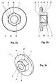
- Electrical busbars in particular in power electronic applications such as converters, conventionally comprise a stack of at least two busbar plates at least partially overlapping, wherein the stack has at least one continuous, in particular circular, hole extending in the stacking direction and guides one screw through the at least one through hole of the stack is, in particular as shown in an embodiment of the prior art according to FIG. 1.
- On the end of the screw usually a common nut is turned on, so that the busbar plates are pressed against each other in their coverage area.
- the mother typically comprises a cylindrical and formed with polygonal cross-section edge element, which has a from a first end side of the edge element to a second end side of the edge element extending through hole, wherein the hole of the edge element has an internal thread which fits in particular to the above-mentioned screw.
- the problem with an electrical busbar according to the prior art according to FIG. 1 is that the mother protrudes significantly beyond the stack of busbar panels due to their height and therefore requires a great deal of space.
- a long screw must be used so that the mother can ever be sufficiently attracted, whereby an increased cost of materials is necessary and increases the weight.
- the respective nut must be held in the assembly until it is screwed on the end of the screw and additionally secured in rotation on the end of the screw with respect to rotation, for example by holding with a tool, resulting in a considerable installation effort, labor and time.
- the object of the invention is therefore to provide a nut, in particular a spring-loaded nut, which requires little space in the assembled state and can be easily and quickly mounted. Furthermore, it is an object of the invention to provide an electrical rail with such a spring-loaded nut, which requires little space, has a low material cost and low weight and can be easily and quickly realized.
- the inventive spring countersunk nut comprises a cylindrical and formed with a polygonal cross-section edge element, which has a running from a first end side of the edge element to a second end side of the edge element through hole.
- a disc element is provided, which is arranged with a first end face on the first end side of the edge element, wherein the Disc element protrudes at the first end side of the edge element.
- the electrical busbar according to the invention comprises a stack of at least two busbar plates at least partially overlapping, the stack having at least one through hole extending in the stacking direction and a screw passing through the at least one through hole of the stack.
- the screw end of the screw for clamping the stack is now screwed into the abovementioned spring-loaded nut according to the invention, wherein the edge element protrudes into the through hole of the stack.
- the inventive spring countersunk nut claimed in the assembled state advantageously only very little space.
- the assembly of the spring-loaded nut can be done very easily and quickly with advantage, as this must be inserted, for example, only with the catenary element in the through hole of the stack of busbar panels at an electrical railing and then guided only the screw in the through hole of the stack and the screw end must be screwed into the spring counternut.
- the disc element of the spring-loaded nut advantageously prevents slippage of the edge element and thus of the entire spring-loaded nut through the through hole of the stack during assembly and also serves to receive the stack pressing forces when tightening the screw.
- the electrical busbar can be realized in a particularly compact and space-saving manner, since the edge element protrudes into the through hole of the stack of busbar plates and only projects beyond the stack.
- the electrical busbar system according to the invention is therefore of particular interest for power electronic applications, for example for traction applications, in which normally very limited space conditions prevail.
- the edge element protrudes into the through hole of the stack of busbar plates, moreover, shorter screws can be used, which advantageously material can be saved and from which a lower weight of the electrical busbar follows.
- the mounting of the inventive electrical busbar advantageously can be particularly simple and fast, since, as already mentioned above, the inventive spring nut must be inserted only with the Katenelement in the through hole of the stack of busbar panels and then only the screw in the continuous Passed hole of the stack and the screw end must be screwed into the spring counternut, the disc element of the spring countersunk with advantage slipping the edge element and thus the entire spring-loaded nut prevented by the through hole of the stack during assembly.
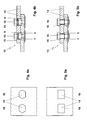
- FIG. 2 a shows a plan view of a first embodiment of the inventive spring-loaded nut, in a side view in FIG. 2 b, and in a three-dimensional view in FIG. 2 c.
- the spring-loaded nut comprises a cylindrical and polygonal cross-section formed edge element 1, which has a from a first end face 2 of the edge element 1 to a second end face 3 of the edge element 1 extending through hole 4.
- a disc element 5 is provided, which has a first end face 6 on the first end side 2 of the edge element 1 is arranged, wherein the disc element 5 protrudes on the first end face 2 of the edge element 1 and this projects beyond it.
- the polygonal cross section of the edge element 1 has at least three corners.
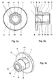
- FIG. 4b additionally shows a first embodiment and in FIG. 5b a second embodiment of an electrical busbar according to the invention, each in a side view.
- the inventive electrical busbar comprises a stack 13 of at least two at least partially covering busbar plates 14, wherein the stack 13 has at least one continuous hole 15 extending in the stacking direction and through the at least one through hole 15 of the stack 13, a screw 16 is guided.
- the screw end of the screw 16 for clamping the stack 13 is now screwed into the already described by way of example with reference to Fig. 2a, Fig. 2b and Fig.
- the inventive spring-loaded nut in the assembled state advantageously requires only a minimum of space. Furthermore, the assembly of the spring-loaded nut can be done very easily and quickly with advantage, since this must be inserted, for example, only with the Katenelement 1 in the through hole 15 of the stack 13 of the rail plates 14 in an electrical rail and then only the screw 16 in the continuous Passed hole 15 of the stack 13 and the end of the screw must be screwed into the spring counternut.
- the disk element 5 of the spring-loaded nut advantageously prevents slippage of the edge element 1 and thus the entire spring-loaded nut through the through hole 15 of the stack 13 during assembly and also serves to receive the stack pressing forces when tightening the screw 16.
- the electrical busbar can be particularly compact and space-saving realized as the edge element 1 in the through hole 15 of the stack 13 of the busbar plates Protrudes 14 and only the disc element 5 on the stack 13, in particular with respect to the stacking direction, protrudes.
- the edge element 1 protrudes into the through hole 15 of the stack 13 of the busbar plates 14, shorter screws 16 can continue to be used, thereby advantageously saving material can be and resulting in a lower weight of the overall electrical busbar results.
- the mounting of the inventive electrical busbar advantageously can be particularly simple and fast, because, as already mentioned above, the inventive spring nut must be inserted only with the Katenelement 1 in the through hole 15 of the stack 13 of the busbar plates 14 and then only the Screw 16 is guided in the through hole 15 of the stack 13 and the end of the screw must be screwed into the spring nut, the disc member 5 of the spring countersunk with advantage slipping of the edge element 1 and thus the whole spring counternut through the through hole 15 of the stack 13 during assembly prevented.
- the part of the disk element 5 which projects beyond the first end face 2 of the edge element 1 is preferably in the direction of the edge element 1, i. in the direction of the cylinder extension direction of the edge element 1, bent.
- a clamping force can be generated on the stack 13 of the screw head of the screw 16, which secures the screw 16 against unintentional twisting, loosening and loosening.
- the disc element 5 with the mentioned bend thus represents an extremely simple and efficient thread lock for the screw 16.
- a biasing force is generated in the stack 13 by the disc element 5 with the mentioned bend, which the stack 13 under changing operating conditions, for example in material expansions due to temperature differences, holds together securely.
- the disk element 5 according to FIGS. 2 a, 2b and 2c preferably has a through hole 8 running from the first end face 6 of the disk element 5 to a second end face 7 of the disk element 5, wherein the hole 8 of the disk element 5 is aligned with the one Hole 4 of the edge element 1 is arranged, so that thus a through hole is formed through the entire spring counternut.
- a through hole is formed through the entire spring counternut.
- the disc element 5 is not necessarily one from the first end side 6 of the disc element 5 to the second end face 7 of the disc element 5 must have running through hole 8, but also without a hole, ie in particular designed as a solid material disc element 5, can be performed.
- a second embodiment of the inventive spring-nut is shown in a plan view, in Fig. 3b in a side view and in Fig. 3c in a three-dimensional view.
- the spring counternut shown therein comprises a cylindrical extension element 9 of circular cross-section which is arranged with a first end face 10 on the second end face 3 of the edge element 1, the circular cross section of the extension element 9 is inscribed in the polygonal cross section of the edge element 1.
- the extension element 9 has a from the first end face 10 of the extension element 9 to a second end face 11 of the extension element 9 extending through hole 12, wherein the hole 12 of the extension element 9 is arranged in alignment with the hole 4 of the edge element 1.
- the extension element 9 serves the improved guidance of the spring-loaded nut during its assembly, for example, in an electrical rail, in particular when inserted into the through hole 15 of the stack 13 of the rail plates 14.
- Fig. 5b shows the already mentioned second embodiment of the inventive electrical busbar in a Side view with Federsenkmuttern according to Fig. 3a, Fig. 3b and Fig. 3c.
- extension element 9 Another advantage of the extension element 9 is that the installation of the electrical busbar can be greatly simplified, since, in particular at a suitable length of the extension element 9, for example in a stack 13 of two busbar plates 14 at least one busbar plate 14 can be temporarily held in position until the associated screw 16 is inserted into the through hole 15 of the stack 13, screwed into the spring counternut and finally tightened. A holding device or additional staff for holding the at least one bus plate 14 in its mounting position is thereby unnecessary.
- the hole 4 of the edge element 1 the hole 8 of the disk element 5 and the hole 12 of the extension element 9 each have an internal thread.
- any other combination is conceivable that, for example, only the Hole 8 of the disc member 5 or only the hole 12 of the extension member 9 has an internal thread etc.
- the edge element 1 preferably forms a piece with the extension element 9. Furthermore, with regard to the embodiments of the spring-loaded nut according to FIGS. 2 a, 2b, 2c, 3a, 3b or 3c, it is also conceivable that the edge element 1 forms a piece with the disk element 5, wherein it However, with respect to the embodiments of the spring-loaded nut according to FIG. 3 a, 3 b or 3 c, it would also be possible for the edge element 1 to form a piece with the disk element 5 and with the extension element 9.
- the one-piece result in improved strength of the spring-loaded nut and a simplified manufacture of the spring-loaded nut, for example by casting and / or forging.
- a first embodiment of the busbar plate 14 of the inventive electrical busbar is shown in a plan view.
- Fig. 5a shows a second embodiment of the busbar plate 14 of the inventive electrical busbar in a plan view.
- the hole of the busbar plate 14 shown by way of example in FIG. 4a and FIG. 5a and thus the through hole 15 of the stack 13 of the busbar plates 14 has a hole wall surface 18 with at least two planar surface parts. It should be understood that the perforated wall surface 18 of the through hole 15 of the stack 13, besides the at least two planar surface portions, would otherwise be generally of any shape, e.g. may have additional surface parts of any shape.
- the edge element 1 is preferably in contact with at least two side surfaces 17 of the edge element 1 on the hole wall surface 18 of the at least one through hole 15 of the stack 14.
- the screw 16 is formed as a countersunk screw and thus protrudes with its screw head into the through hole 15 of the stack 13 and thus not or only slightly above the Stack 13 protrudes.
- Fig. 6 is exemplified a third embodiment of the inventive electrical busbar with such a countersunk screw, in particular with bevelled Screw head surface, shown. It is understood that when using such a kind of countersunk screw parts of the inner hole surface 18 of the through hole 15 of the stack 13 should be formed for receiving the screw head of the countersunk screw.
Landscapes
- Engineering & Computer Science (AREA)
- General Engineering & Computer Science (AREA)
- Mechanical Engineering (AREA)
- Connections By Means Of Piercing Elements, Nuts, Or Screws (AREA)
Priority Applications (1)
| Application Number | Priority Date | Filing Date | Title |
|---|---|---|---|
| EP06405222A EP1860334A1 (fr) | 2006-05-23 | 2006-05-23 | Dispositif de ressorts conique et ensemble de raccordement électrique comprenant un tel dispositif |
Applications Claiming Priority (1)
| Application Number | Priority Date | Filing Date | Title |
|---|---|---|---|
| EP06405222A EP1860334A1 (fr) | 2006-05-23 | 2006-05-23 | Dispositif de ressorts conique et ensemble de raccordement électrique comprenant un tel dispositif |
Publications (1)
| Publication Number | Publication Date |
|---|---|
| EP1860334A1 true EP1860334A1 (fr) | 2007-11-28 |
Family
ID=36968752
Family Applications (1)
| Application Number | Title | Priority Date | Filing Date |
|---|---|---|---|
| EP06405222A Withdrawn EP1860334A1 (fr) | 2006-05-23 | 2006-05-23 | Dispositif de ressorts conique et ensemble de raccordement électrique comprenant un tel dispositif |
Country Status (1)
| Country | Link |
|---|---|
| EP (1) | EP1860334A1 (fr) |
Cited By (3)
| Publication number | Priority date | Publication date | Assignee | Title |
|---|---|---|---|---|
| EP2642136A1 (fr) * | 2012-03-19 | 2013-09-25 | Alstom Technology Ltd | Structure de couplage et procédé pour relier des parties de couplage |
| WO2016051035A1 (fr) * | 2014-10-02 | 2016-04-07 | Peugeot Citroen Automobiles Sa | Moyeu d'essieu de véhicule à écrous à réserve élastique pour la solidarisation d'une roue à voile à zones de passage de vis sensiblement planes |
| US11152830B2 (en) * | 2019-01-28 | 2021-10-19 | Siemens Energy, Inc. | Isolated bolting connection for a generator |
Citations (5)
| Publication number | Priority date | Publication date | Assignee | Title |
|---|---|---|---|---|
| FR616097A (fr) * | 1926-06-11 | 1927-01-22 | Perfectionnements dans les boulons et leurs écrous | |
| GB683868A (en) * | 1950-05-05 | 1952-12-03 | United Carr Fastener Corp | Improvements in and relating to flanged nut assemblies |
| US4293256A (en) * | 1979-11-09 | 1981-10-06 | The Lamson & Sessions Co. | Load indicating fastener |
| US4671583A (en) * | 1983-02-24 | 1987-06-09 | The Boeing Company | Fastening device and method for composite structures |
| US6027293A (en) * | 1999-01-15 | 2000-02-22 | Deere & Company | Nut retaining plate |
-
2006
- 2006-05-23 EP EP06405222A patent/EP1860334A1/fr not_active Withdrawn
Patent Citations (5)
| Publication number | Priority date | Publication date | Assignee | Title |
|---|---|---|---|---|
| FR616097A (fr) * | 1926-06-11 | 1927-01-22 | Perfectionnements dans les boulons et leurs écrous | |
| GB683868A (en) * | 1950-05-05 | 1952-12-03 | United Carr Fastener Corp | Improvements in and relating to flanged nut assemblies |
| US4293256A (en) * | 1979-11-09 | 1981-10-06 | The Lamson & Sessions Co. | Load indicating fastener |
| US4671583A (en) * | 1983-02-24 | 1987-06-09 | The Boeing Company | Fastening device and method for composite structures |
| US6027293A (en) * | 1999-01-15 | 2000-02-22 | Deere & Company | Nut retaining plate |
Cited By (4)
| Publication number | Priority date | Publication date | Assignee | Title |
|---|---|---|---|---|
| EP2642136A1 (fr) * | 2012-03-19 | 2013-09-25 | Alstom Technology Ltd | Structure de couplage et procédé pour relier des parties de couplage |
| WO2016051035A1 (fr) * | 2014-10-02 | 2016-04-07 | Peugeot Citroen Automobiles Sa | Moyeu d'essieu de véhicule à écrous à réserve élastique pour la solidarisation d'une roue à voile à zones de passage de vis sensiblement planes |
| FR3026676A1 (fr) * | 2014-10-02 | 2016-04-08 | Peugeot Citroen Automobiles Sa | Moyeu d’essieu de vehicule a ecrous a reserve elastique pour la solidarisation d’une roue a voile a zones de passage de vis sensiblement planes |
| US11152830B2 (en) * | 2019-01-28 | 2021-10-19 | Siemens Energy, Inc. | Isolated bolting connection for a generator |
Similar Documents
| Publication | Publication Date | Title |
|---|---|---|
| EP1956250B1 (fr) | Profilé de type rail | |
| DE69620101T2 (de) | Sammelschienenanordnung mit Befestigungsmitteln hierfür | |
| EP0353468A1 (fr) | Elément de connexion | |
| EP1899613B1 (fr) | Vis d'ancrage | |
| EP0653583A2 (fr) | Joint à brides | |
| DE102005000129A1 (de) | Befestigungsvorrichtung für die Befestigung von Solarpaneelen an einer Montageschiene | |
| DE29602589U1 (de) | Kastenschleifleitung | |
| DE19825426B4 (de) | In eine T-Nut einsetzbarer Näherungsschalter bzw. Befestigungselement dafür | |
| EP1860334A1 (fr) | Dispositif de ressorts conique et ensemble de raccordement électrique comprenant un tel dispositif | |
| EP0808946B1 (fr) | Fixation de rail | |
| DE10219245B4 (de) | Verfahren zum Trennen einer Geberwelle eines Drehgebers von einer Antriebswelle | |
| EP3333982B1 (fr) | Adaptateur de raccordement permettant de raccorder un appareil électrique ainsi que système et installation électrique | |
| DE202011003315U1 (de) | Verbindungsvorrichtung | |
| EP0943824A1 (fr) | Dispositif de fixation | |
| DE102007014357A1 (de) | Polklemme mit Verdrehsicherungselement | |
| DE4138547C1 (en) | Pole terminal clamp esp. for car battery - has inclined surface formed on small end face of at least one bowed flange extending in parallel to axis of recess in flat material part | |
| DE4338719A1 (de) | Flanschverbindung | |
| DE3811629C1 (en) | Pole terminal | |
| EP0263390A2 (fr) | Borne à vis | |
| DE69305423T2 (de) | Verkehrszeichen | |
| EP0860837B1 (fr) | Isolateur et adapteur pour fils, bandes ou torons sous tension électrique pour monter et fabriquer des clôtures | |
| DE202013100120U1 (de) | T-Verbindung für eine Pfosten-Riegel-Konstruktion | |
| DE102019202316A1 (de) | Anschluss eines Sicherheitszaunfeldes an einem Zaunpfosten oder sonstigen Zaunträger und Sicherheitszaun | |
| DE4404057C2 (de) | Anschlußklemme mit Spreizelement | |
| DE1199349B (de) | Elektrische Buegelklemme |
Legal Events
| Date | Code | Title | Description |
|---|---|---|---|
| PUAI | Public reference made under article 153(3) epc to a published international application that has entered the european phase |
Free format text: ORIGINAL CODE: 0009012 |
|
| AK | Designated contracting states |
Kind code of ref document: A1 Designated state(s): AT BE BG CH CY CZ DE DK EE ES FI FR GB GR HU IE IS IT LI LT LU LV MC NL PL PT RO SE SI SK TR |
|
| AX | Request for extension of the european patent |
Extension state: AL BA HR MK YU |
|
| AKX | Designation fees paid | ||
| REG | Reference to a national code |
Ref country code: DE Ref legal event code: 8566 |
|
| STAA | Information on the status of an ep patent application or granted ep patent |
Free format text: STATUS: THE APPLICATION IS DEEMED TO BE WITHDRAWN |
|
| 18D | Application deemed to be withdrawn |
Effective date: 20080529 |