EP0808807B1 - Processing of glass tubes, manufacture of closed-loop tubular lamp and lamps therefrom - Google Patents
Processing of glass tubes, manufacture of closed-loop tubular lamp and lamps therefrom Download PDFInfo
- Publication number
- EP0808807B1 EP0808807B1 EP97107737A EP97107737A EP0808807B1 EP 0808807 B1 EP0808807 B1 EP 0808807B1 EP 97107737 A EP97107737 A EP 97107737A EP 97107737 A EP97107737 A EP 97107737A EP 0808807 B1 EP0808807 B1 EP 0808807B1
- Authority
- EP
- European Patent Office
- Prior art keywords
- tube
- tubes
- blister
- dome
- glass tube
- Prior art date
- Legal status (The legal status is an assumption and is not a legal conclusion. Google has not performed a legal analysis and makes no representation as to the accuracy of the status listed.)
- Expired - Lifetime
Links
Images


Classifications
-
- C—CHEMISTRY; METALLURGY
- C03—GLASS; MINERAL OR SLAG WOOL
- C03B—MANUFACTURE, SHAPING, OR SUPPLEMENTARY PROCESSES
- C03B23/00—Re-forming shaped glass
- C03B23/20—Uniting glass pieces by fusing without substantial reshaping
- C03B23/207—Uniting glass rods, glass tubes, or hollow glassware
-
- C—CHEMISTRY; METALLURGY
- C03—GLASS; MINERAL OR SLAG WOOL
- C03B—MANUFACTURE, SHAPING, OR SUPPLEMENTARY PROCESSES
- C03B23/00—Re-forming shaped glass
- C03B23/04—Re-forming tubes or rods
- C03B23/06—Re-forming tubes or rods by bending
- C03B23/065—Re-forming tubes or rods by bending in only one plane, e.g. for making circular neon tubes
-
- C—CHEMISTRY; METALLURGY
- C03—GLASS; MINERAL OR SLAG WOOL
- C03B—MANUFACTURE, SHAPING, OR SUPPLEMENTARY PROCESSES
- C03B23/00—Re-forming shaped glass
- C03B23/04—Re-forming tubes or rods
- C03B23/07—Re-forming tubes or rods by blowing, e.g. for making electric bulbs
-
- C—CHEMISTRY; METALLURGY
- C03—GLASS; MINERAL OR SLAG WOOL
- C03B—MANUFACTURE, SHAPING, OR SUPPLEMENTARY PROCESSES
- C03B23/00—Re-forming shaped glass
- C03B23/04—Re-forming tubes or rods
- C03B23/09—Reshaping the ends, e.g. as grooves, threads or mouths
- C03B23/096—Reshaping the ends, e.g. as grooves, threads or mouths by bending
-
- C—CHEMISTRY; METALLURGY
- C03—GLASS; MINERAL OR SLAG WOOL
- C03B—MANUFACTURE, SHAPING, OR SUPPLEMENTARY PROCESSES
- C03B23/00—Re-forming shaped glass
- C03B23/04—Re-forming tubes or rods
- C03B23/09—Reshaping the ends, e.g. as grooves, threads or mouths
- C03B23/099—Reshaping the ends, e.g. as grooves, threads or mouths by fusing, e.g. flame sealing
-
- H—ELECTRICITY
- H01—ELECTRIC ELEMENTS
- H01J—ELECTRIC DISCHARGE TUBES OR DISCHARGE LAMPS
- H01J61/00—Gas-discharge or vapour-discharge lamps
- H01J61/02—Details
- H01J61/30—Vessels; Containers
- H01J61/32—Special longitudinal shape, e.g. for advertising purposes
- H01J61/322—Circular lamps
-
- H—ELECTRICITY
- H01—ELECTRIC ELEMENTS
- H01J—ELECTRIC DISCHARGE TUBES OR DISCHARGE LAMPS
- H01J65/00—Lamps without any electrode inside the vessel; Lamps with at least one main electrode outside the vessel
- H01J65/04—Lamps in which a gas filling is excited to luminesce by an external electromagnetic field or by external corpuscular radiation, e.g. for indicating plasma display panels
- H01J65/042—Lamps in which a gas filling is excited to luminesce by an external electromagnetic field or by external corpuscular radiation, e.g. for indicating plasma display panels by an external electromagnetic field
- H01J65/048—Lamps in which a gas filling is excited to luminesce by an external electromagnetic field or by external corpuscular radiation, e.g. for indicating plasma display panels by an external electromagnetic field the field being produced by using an excitation coil
-
- H—ELECTRICITY
- H01—ELECTRIC ELEMENTS
- H01J—ELECTRIC DISCHARGE TUBES OR DISCHARGE LAMPS
- H01J9/00—Apparatus or processes specially adapted for the manufacture, installation, removal, maintenance of electric discharge tubes, discharge lamps, or parts thereof; Recovery of material from discharge tubes or lamps
- H01J9/24—Manufacture or joining of vessels, leading-in conductors or bases
- H01J9/26—Sealing together parts of vessels
-
- H—ELECTRICITY
- H01—ELECTRIC ELEMENTS
- H01J—ELECTRIC DISCHARGE TUBES OR DISCHARGE LAMPS
- H01J61/00—Gas-discharge or vapour-discharge lamps
- H01J61/70—Lamps with low-pressure unconstricted discharge having a cold pressure < 400 Torr
- H01J61/72—Lamps with low-pressure unconstricted discharge having a cold pressure < 400 Torr having a main light-emitting filling of easily vaporisable metal vapour, e.g. mercury
Definitions
- This invention relates to a method for processing a glass tube for connection to another glass tube and to electrodeless low pressure light sources and, more particularly, to a closed-loop, tubular lamp envelope and methods of manufacturing closed-loop, tubular lamp envelopes.
- DE-A-42 02 485 discloses a method for processing a glass tube for connecting two glass tubes in a 180° bending.
- An irregular shaped dome is formed at the end of the glass tubes, and then molded to a special shape as a whole.
- a hole is formed in said dome and the tube is connected to another glass tube. This results in a low pressure fluorescent lamp with parallel straight tube portions connected by a bridge formed by two blowed and moulded normal sections provided with rims.
- US-A-4 864 194 discloses a closed-loop tubular envelope with two straight glass tubes which are connected via narrow flat portions. An electric lead is wound around the surface of the envelope to induce high frequency into the envelope.
- Electrodeless fluorescent lamps are disclosed in U.S. Patent No. 3,500,118 issued March 10, 1970 to Anderson; U.S. Patent No. 3,987,334 issued October 19, 1976 to Anderson; and Anderson, Illuminating Engineering , April 1969, pages 236 to 244.
- An electrodeless, inductively-coupled lamp as disclosed in these references, includes a low pressure mercury/buffer gas discharge in a discharge tube which forms a continuous closed electrical path. The path of the discharge tube goes through the center of one or more toroidal ferrite cores such that the discharge tube becomes the secondary of a transformer. Power is coupled to the discharge by applying a sinusoidal voltage to a few turns of wire wound around the toroidal core that encircles the discharge tube.
- a current through the primary winding creates a time-varying magnetic flux which induces along the discharge tube a voltage that maintains the discharge.
- the inner surface of the discharge tube is coated with a phosphor which emits visible light when irradiated by photons emitted by the excited mercury atoms.
- the lamp parameters described by Anderson produce a lamp which has high core loss and is therefore extremely inefficient. In addition, the Anderson lamp is impractically heavy because of the ferrite material used in the transformer core.
- the disclosed lamp assembly comprises an electrodeless lamp including a closed-loop, tubular lamp envelope enclosing mercury vapor and a buffer gas at a pressure less than about 0,67 mbar (0.5 torr), a transformer core disposed around the lamp envelope, an input winding disposed on the transformer core and a radio frequency power source coupled to the input winding.
- the radio frequency source supplies sufficient radio frequency energy to the mercury vapor and the buffer gas to produce in the lamp envelope a discharge having a discharge current equal to or greater than about 2 amperes.
- the disclosed lamp assembly achieves relatively high lumen output, high efficacy and high axial lumen density simultaneously, thus making it an attractive alternative to conventional VHO fluorescent lamps and high intensity, high pressure discharge lamps.
- Electrodeless lamps of the type described above require a closed-loop, tubular lamp envelope.
- the lamp envelope is hollow and forms a closed-loop but may have a variety of different shapes.
- the aforementioned Patent No. 3,500,118 discloses an oval shaped lamp envelope.
- a toroidal lamp envelope having a constricted section for ferrite placement is disclosed in the aforementioned Patent No. 3,987,334.
- Japanese Document No. 7-94152 discloses electrodeless lamp envelopes of various shapes, wherein two halves are joined in two places to form a ring.
- No. 7-94152 discloses the joining of formed glass tubes at abutting tube ends.
- a method for processing a glass tube for connection to another glass tube possibly used for fabricating a closed-loop, tubular lamp envelope, is provided.
- a hemispherical dome is formed at one end of a light-transmissive tube.
- a blister is moulded on the dome and from a portion thereof, and a hole is formed in the molded blister.
- the moulded blister includes a rim which defines the respective hole and is adapted for connection to another glass tube.
- the light-transmissive tube may be bent in one or more places to form a desired shape of a lamp envelope.
- the rims at the ends of the glass tubes form matching half bridges for joining the first and second tubes.
- a method for connecting glass tubes comprises the steps of processing a second glass tube in the same way.
- the first and second glass tubes are joined at the rims to form a sealed connection between the first and second glass tubes.
- a closed-loop, tubular lamp envelope is provided.
- a first and a second light-transmissive tubes have first and second hemispherically/shaped domes at opposite ends thereof.
- said light-tansmissive tubes are joined to each other at their respective domer by respective tubular bridges having cylindrical walls with a circular cross-section, in such a may that said tubes form a sealed, closed-loop, tubular lamp envelope.
- the first and second tubes have straight portions and are joined together by matching half bridges.
- a closed-loop, hollow, tubular glass envelope is produced by shaping and processing of tube sections that are then fused together at well-defined sealing surfaces.
- the process typically involves prefabrication of two sections, but is not limited to two sections.
- the tube sections are made to a tight tolerance to be sure that the sealing surfaces match.
- the final lamp envelope must be reliably sealed, must be relatively rugged and must have a long operating life. Reproducibility and high process yield depend on achievement of a good match between the tube sections to be joined together.
- a process for prefabricating a glass tube in preparation for joining the glass tube to another glass tube is described with reference to FIGS. 1-4.
- the process begins with a straight glass tube 10 of desired diameter, wall thickness and composition.
- a dome 12 is formed on one end of glass tube 10.
- the dome 12 may be formed by placing the glass tube in a lathe, heating the glass tube in the region where the dome is to be formed, rotating the glass tube and pulling the ends of the glass tube apart. Automated techniques for forming dome 12 are well known to those skilled in the art.
- the dome has a hemispherical shape with a diameter equal to the diameter of glass tube 10. The dome 12 closes one end of glass tube 10.
- the dome 12 is shaped to form a precursor to a rimmed hole.
- the dome 12 may be shaped using a moulding process such as blow moulding, to form a blister 20.
- the blister 20 includes a rim 22 having a closed end 24.
- the blister 20 may be formed by heating dome 12 and pressurizing the interior of glass tube 10 so as to force a portion of dome 12 into a mould (not shown) having the shape of blister 20.
- the mould defines the exterior size and shape of blister 20.
- the wall thickness of rim 22 is determined by the thickness of dome 12, typically about the same as the wall thickness of glass tube 10.
- the closed end of blister 20 is removed to form a hole 26 defined by rim 22.
- the hole 26 is formed through blister 20 by flame cutting.
- the rim 22 comprises a cylindrical wall and defines a circular hole.
- the rim 22 of hole 26 can be formed in any desired location on dome 12. In order to assure a round rim, the blister 20 must be fully located on dome 12. The degree of freedom in positioning hole 26 depends on the required size of hole 26. A smaller hole may be positioned within a larger solid angle on the dome than a large hole. Nonetheless, the process shown in FIGS. 1-4 and described above provides flexibility with respect to the size and position of hole 26 and its orientation with respect to the axis of glass tube 10. Because rim 22 is moulded, its shape and dimensions are well controlled.
- FIG. 5 A glass tube 30 having a dome 32 and a rim 36 is processed in the same manner as glass tube 10 described above.
- the rims 22 and 36 have the same diameters, preferably within about 0.2 to 0.3 mm, and the same wall thickness as a result of the moulding process used to form the rims.
- the rims 22 and 36 are aligned within a few degrees and are fused together to form a sealed joint 40. Because the rims 22 and 36 are formed in the same mould, they are closely matched and permit accurate fusing and sealing between tubes 10 and 30.
- the tubes 10 and 30 typically have the same diameters and wall thicknesses. However, tubes of different dimensions may be joined using the process of the present invention.
- the principal requirement is that the rims 22 and 36 be sufficiently matched to permit them to be fused together.
- the fusing of rims 22 and 36 is performed by heating these elements to melting conditions and pressing them together as known in the art.
- FIGS. 1-4 The process shown in FIGS. 1-4 and described above is performed on a straight glass tube having a dome formed at one end. In many cases, it may be desired to bend the glass tube adjacent to dome 12 so that, for example, the plane of rim 22 may be oriented parallel to the axis of glass tube 10. As described below, the process of FIGS. 1-4 can be performed on both ends of two glass tubes, and the two glass tubes can be joined together to form a closed-loop lamp envelope.
- the described procedure can be used on straight and shaped glass tubing. Using the disclosed process and different tube shapes and sizes, a large variety of lamp configurations can be fabricated. The disclosed procedure permits an extremely flexible manufacturing process, capable of handling different shapes and sizes with very little changeover.
- FIGS. 6 and 7 Examples of closed-loop, hollow tubular lamp envelopes fabricated in accordance with the present invention are illustrated in FIGS. 6 and 7.
- a lamp envelope 50 is formed by joining glass tubes 52 and 54.
- a rim 56 is formed in a dome 58 at one end of glass tube 52
- a rim 60 is formed in a dome 62 at the other end of glass tube 52.
- a rim 66 is formed in a dome 68 at one end of glass tube 54
- a rim 70 is formed in a dome 72 at the other end of glass tube 54.
- Each of the glass tubes 52 and 54 is shaped near one end to permit formation of a closed-loop lamp envelope and to provide a desired shape.
- Rim 56 of glass tube 52 is joined to rim 70 of glass tube 54 at joint 76
- rim 60 of glass tube 52 is joined to rim 66 of glass tube 54 at joint 78 to form the sealed, closed-loop lamp envelope 50.
- a lamp envelope 90 having a different shape from lamp envelope 50 but fabricated by the same process is shown in FIG. 7.
- Glass tube 92 is fabricated with rims 94 and 96, and glass tube 100 is fabricated with rims 102 and 104 as described above.
- Rim 96 is fused to rim 104 at joint 110, and rim 94 is fused to rim 102 at joint 112 to form the sealed, closed-loop lamp envelope 90.
- a preferred configuration of a lamp envelope 120 for an electrodeless light source is shown in FIG. 8.
- the lamp envelope 120 includes glass tubes 122 and 124 joined at or near each end by bridges 126 and 128 to form a closed-loop. Bridges 126 and 128 are formed by integral half bridges on glass tubes 122 and 124.
- Glass tubes 122 and 124 Straight portions of glass tubes 122 and 124 are parallel and spaced apart.
- the glass tubes 122 and 124 are fused at joints 130 and 132 to form a sealed lamp envelope having a closed-loop discharge path.
- the tubes 122 and 124 have outside diameters of 5.0 centimeters and are spaced apart, except at bridges 126 and 128, by 2.8 centimeters.
- the overall length of the lamp envelope, not including the tubulation, is 40.0 centimeters.
- the bridges 126 and 128 have outside diameters of 3.4 centimeters.
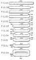
- a process for fabricating a closed-loop, hollow lamp envelope of the type shown in FIG. 8 is described with reference to FIGS. 9 and 10A-10K. It will be understood that this process is generally applicable to fabrication of closed-loop, tubular lamp envelopes of different shapes and sizes.
- a glass tube 300 (FIG. 10A) is cut to a desired length in step 200.
- a hemispherical dome 302 (FIG. 10B) is formed in a first end of glass tube 300 in step 202.
- the domed end of tube 300 is bent, as indicated at 304 in FIG. 10C, at a 45° angle to the tube axis in step 204.
- the first 302 is moulded using a blow moulding procedure to form a blister 306 (FIG.
- step 206 The blister is opened to form a hole 308 (FIG. 10E) defined by a rim 310 in step 208.
- a dome 320 (FIG. 10F) is formed at the second end of tube 300 in step 210.
- the second end of tube 300 is bent, as indicated at 322 in FIG. 10G, at a 45° angle to the tube axis in step 212.
- the second end of tube 300 is blow moulded to form a blister 324 (FIG. 10H) in step 214.
- the blister 324 is opened to form a hole 326 (FIG. 10I) defined by a rim 328 in step 216.
- the inside surface of the glass tube 300 is coated with a phosphor material in step 218. More specifically, the lamp tube may be internally coated with an aluminum oxide barrier coating. After oven drying of the barrier coating, the lamp tube is coated with a 3500K triphosphor blend, dried and baked, as is known in the art. The phosphor coating is wiped from the open ends of glass tube 300 in the region adjacent to rims 310 and 328 where the glass seals will be made.
- steps 200 through 218 are repeated for a second glass tube 340 (FIG. 10K) in step 220.
- Each of the tubes has a half bridge at each end.
- One or more exhaust tubes 334 (FIG. 10J) may be attached to either or both of the formed glass tubes.
- the two formed glass tubes 300 and 340 are fused together at their matching rims on a joining machine to form the closed-loop lamp envelope (FIG. 10K) in step 224.
- Lamp exhaust processing is similar to that used for other fluorescent lamps. While heated in an oven to outgas the glass and the phosphors, the lamp envelope is subjected to repeated cycles of flushing with an inert gas and evacuation.
- the final fill gas which may be krypton, is preferably introduced at a pressure of 0,27 mbar (0.2 torr). Doses of mercury and amalgam are introduced, and the exhaust tube 334 is tipped off to provide a completed lamp envelope as shown in FIG. 8.
- the precision spacing between the half bridges and the coplanarity of their cut open ends is crucial to the ability to seal the glass tubes together.
- the rims on the half bridges should be aligned within about 0.2 to 0.3 mm and should be coplanar within a few degrees.
- the opposite ends of the glass tubes are preferably sealed simultaneously.
Landscapes
- Chemical & Material Sciences (AREA)
- Engineering & Computer Science (AREA)
- Materials Engineering (AREA)
- Organic Chemistry (AREA)
- Physics & Mathematics (AREA)
- Electromagnetism (AREA)
- Plasma & Fusion (AREA)
- Manufacturing & Machinery (AREA)
- Manufacture Of Electron Tubes, Discharge Lamp Vessels, Lead-In Wires, And The Like (AREA)
- Vessels And Coating Films For Discharge Lamps (AREA)
- Discharge Lamps And Accessories Thereof (AREA)
- Formation Of Various Coating Films On Cathode Ray Tubes And Lamps (AREA)
Applications Claiming Priority (2)
| Application Number | Priority Date | Filing Date | Title |
|---|---|---|---|
| US650245 | 1996-05-22 | ||
| US08/650,245 US5722549A (en) | 1996-05-22 | 1996-05-22 | Closed-loop tubular lamp envelope and method of manufacture |
Publications (2)
| Publication Number | Publication Date |
|---|---|
| EP0808807A1 EP0808807A1 (en) | 1997-11-26 |
| EP0808807B1 true EP0808807B1 (en) | 2002-03-06 |
Family
ID=24608095
Family Applications (1)
| Application Number | Title | Priority Date | Filing Date |
|---|---|---|---|
| EP97107737A Expired - Lifetime EP0808807B1 (en) | 1996-05-22 | 1997-05-12 | Processing of glass tubes, manufacture of closed-loop tubular lamp and lamps therefrom |
Country Status (9)
| Country | Link |
|---|---|
| US (2) | US5722549A (zh) |
| EP (1) | EP0808807B1 (zh) |
| JP (1) | JP3987603B2 (zh) |
| KR (1) | KR100459777B1 (zh) |
| CN (1) | CN1089480C (zh) |
| CA (1) | CA2205707C (zh) |
| DE (1) | DE69710812T2 (zh) |
| HU (1) | HU218812B (zh) |
| TW (1) | TW479263B (zh) |
Families Citing this family (13)
| Publication number | Priority date | Publication date | Assignee | Title |
|---|---|---|---|---|
| US6391809B1 (en) * | 1999-12-30 | 2002-05-21 | Corning Incorporated | Copper alumino-silicate glasses |
| KR20020080787A (ko) | 2001-04-17 | 2002-10-26 | 강성진 | 3차원 구조를 갖는 무전극 형광 램프 |
| KR100729282B1 (ko) * | 2004-07-15 | 2007-06-20 | 조정열 | 다양한 모양 및 크기를 갖는 외부 전극 형광 램프 제조방법 및 그 방법에 사용되는 유닛화된 구조의 유리관 |
| DE102004034807A1 (de) * | 2004-07-19 | 2006-03-16 | Ip2H Ag | Lichtquelle und ein Verfahren zur mechanischen Stabilisierung des Filaments oder der Elektrode einer Lichtquelle |
| KR100727040B1 (ko) | 2005-09-09 | 2007-06-12 | 금호전기주식회사 | 듀얼 브리지 무전극 형광램프의 램프 밀봉체 제조 방법 |
| JP4798009B2 (ja) * | 2007-01-26 | 2011-10-19 | パナソニック電工株式会社 | 無電極放電灯装置および照明器具 |
| JP4956224B2 (ja) * | 2007-02-23 | 2012-06-20 | パナソニック株式会社 | 無電極放電灯の製造方法、該製造方法によって製造された無電極放電灯、並びに、該無電極放電灯を用いた照明器具 |
| JP2008282743A (ja) * | 2007-05-11 | 2008-11-20 | Nippo Electric Co Ltd | 照明ランプ |
| JP2009151969A (ja) * | 2007-12-19 | 2009-07-09 | Hoya Candeo Optronics株式会社 | エキシマランプ、その製造方法および光源装置 |
| KR100912666B1 (ko) * | 2008-01-04 | 2009-08-17 | 금호전기주식회사 | 무전극 형광 램프의 제조방법 |
| KR100917017B1 (ko) * | 2008-01-08 | 2009-09-10 | 금호전기주식회사 | 표면 처리가 적용된 무전극 형광 램프 |
| CN102468113B (zh) * | 2010-10-28 | 2015-06-24 | 烟台茂翔电子科技有限公司 | 一种无极灯灯管及其常温连接方法 |
| DE102019217150A1 (de) * | 2019-11-06 | 2021-05-06 | De Dietrich Process Systems Gmbh | Glasfläche für ein Glasgefäß, dessen Herstellung und Verwendung |
Family Cites Families (27)
| Publication number | Priority date | Publication date | Assignee | Title |
|---|---|---|---|---|
| US2392785A (en) * | 1945-03-28 | 1946-01-08 | Sylvania Electric Prod | Lamp base |
| FR1139622A (fr) * | 1966-08-01 | 1957-07-03 | Du Pont | Réglage du ph dans les processus de dépôt électrolytique |
| US3500118A (en) * | 1967-07-17 | 1970-03-10 | Gen Electric | Electrodeless gaseous electric discharge devices utilizing ferrite cores |
| US4027363A (en) * | 1973-06-22 | 1977-06-07 | Belknap Donald J | Methods of making incandescent lamps |
| US3987334A (en) * | 1975-01-20 | 1976-10-19 | General Electric Company | Integrally ballasted electrodeless fluorescent lamp |
| HU174714B (hu) * | 1977-01-06 | 1980-03-28 | Egyesuelt Izzolampa | Ehlektricheskaja razrjadnaja lampa |
| US4121132A (en) * | 1977-09-28 | 1978-10-17 | Westinghouse Electric Corp. | Phosphor coating method and resulting fluorescent lamp |
| NL187138C (nl) * | 1979-04-03 | 1991-06-03 | Philips Nv | Werkwijze voor het vervaardigen van een lagedrukkwikdampontladingslamp. |
| JPS59103245A (ja) * | 1982-12-06 | 1984-06-14 | Mitsubishi Electric Corp | 放電ランプの製造方法 |
| JPS61224236A (ja) * | 1985-03-27 | 1986-10-04 | Toshiba Corp | 曲管形けい光ランプの製造方法 |
| US4787865A (en) * | 1986-12-04 | 1988-11-29 | North American Philips Lighting Corp. | Three-way lamp bases and method for making them |
| US4850500A (en) * | 1986-12-18 | 1989-07-25 | Gte Products Corporation | Dimpled arc tube having no internal end pockets and a lamp employing same |
| JPS6379730A (ja) * | 1987-03-06 | 1988-04-09 | Toshiba Corp | ガラス管の接合方法 |
| US4864194A (en) * | 1987-05-25 | 1989-09-05 | Matsushita Electric Works, Ltd. | Electrodeless discharge lamp device |
| KR920003545B1 (ko) * | 1987-07-01 | 1992-05-02 | 가부시끼가이샤 도시바 | 링형 유리발브 및 이를 사용한 램프 어셈블리 |
| JPS6465747A (en) * | 1987-09-04 | 1989-03-13 | Matsushita Electric Works Ltd | Manufacture of electrodeless discharge lamp |
| US5124618A (en) * | 1989-11-16 | 1992-06-23 | Matsushita Electronics Corporation | Shatter-proof fluorescent lamp |
| JPH03252027A (ja) * | 1990-02-28 | 1991-11-11 | Toshiba Lighting & Technol Corp | けい光ランプの製造方法 |
| DE4202485A1 (de) * | 1992-01-27 | 1993-07-29 | Dieter Krebs | Niederdruckgasentladungslampengefaess und verfahren zur herstellung |
| GB2277634B (en) * | 1993-04-27 | 1996-09-04 | Mass Technology | Method of producing a low-pressure mercury vapour discharge lamp |
| JP3408588B2 (ja) * | 1993-09-22 | 2003-05-19 | 池田電機株式会社 | 無電極放電灯点灯装置 |
| JPH0794152A (ja) * | 1993-09-27 | 1995-04-07 | Ikeda Electric Co Ltd | 無電極放電灯 |
| DE4403260A1 (de) * | 1994-02-03 | 1995-08-10 | Dieter Strueber | Entladungslampe sowie Verfahren zur Herstellung einer solchen |
| BE1007913A3 (nl) * | 1993-12-24 | 1995-11-14 | Philips Electronics Nv | Lagedrukontladingslamp en werkwijze voor het vervaardigen van een lagedrukontladingslamp. |
| US5723939A (en) * | 1994-12-28 | 1998-03-03 | Matsushita Electronics Corporation | Circular fluorescent lamp |
| US5834905A (en) * | 1995-09-15 | 1998-11-10 | Osram Sylvania Inc. | High intensity electrodeless low pressure light source driven by a transformer core arrangement |
| JP2912863B2 (ja) * | 1995-11-27 | 1999-06-28 | 松下電子工業株式会社 | 環形蛍光ランプの製造方法 |
-
1996
- 1996-05-22 US US08/650,245 patent/US5722549A/en not_active Expired - Lifetime
-
1997
- 1997-04-02 TW TW086104236A patent/TW479263B/zh not_active IP Right Cessation
- 1997-05-12 DE DE69710812T patent/DE69710812T2/de not_active Expired - Lifetime
- 1997-05-12 EP EP97107737A patent/EP0808807B1/en not_active Expired - Lifetime
- 1997-05-20 CA CA002205707A patent/CA2205707C/en not_active Expired - Fee Related
- 1997-05-21 KR KR1019970019658A patent/KR100459777B1/ko not_active IP Right Cessation
- 1997-05-21 HU HU9700929A patent/HU218812B/hu not_active IP Right Cessation
- 1997-05-22 JP JP13222497A patent/JP3987603B2/ja not_active Expired - Fee Related
- 1997-05-22 CN CN97113440.5A patent/CN1089480C/zh not_active Expired - Lifetime
- 1997-09-26 US US08/938,114 patent/US5932961A/en not_active Expired - Lifetime
Also Published As
| Publication number | Publication date |
|---|---|
| DE69710812T2 (de) | 2002-09-26 |
| JPH1050218A (ja) | 1998-02-20 |
| HUP9700929A2 (en) | 1997-12-29 |
| KR970077069A (ko) | 1997-12-12 |
| CA2205707C (en) | 2006-01-10 |
| CN1173606A (zh) | 1998-02-18 |
| HU218812B (hu) | 2000-12-28 |
| US5932961A (en) | 1999-08-03 |
| HUP9700929A3 (en) | 1999-09-28 |
| KR100459777B1 (ko) | 2005-02-28 |
| CA2205707A1 (en) | 1997-11-22 |
| US5722549A (en) | 1998-03-03 |
| HU9700929D0 (en) | 1997-07-28 |
| EP0808807A1 (en) | 1997-11-26 |
| DE69710812D1 (de) | 2002-04-11 |
| CN1089480C (zh) | 2002-08-21 |
| TW479263B (en) | 2002-03-11 |
| JP3987603B2 (ja) | 2007-10-10 |
Similar Documents
| Publication | Publication Date | Title |
|---|---|---|
| EP0808807B1 (en) | Processing of glass tubes, manufacture of closed-loop tubular lamp and lamps therefrom | |
| US4196374A (en) | Compact fluorescent lamp and method of making | |
| US4324447A (en) | Method of producing a low-pressure mercury vapor discharge lamp | |
| US20060194503A1 (en) | Method of making three-dimensional electrodeless fluorescent lamp | |
| US20070001610A1 (en) | Ceramic lamp having molybdenum-rhenium end cap and systems and methods therewith | |
| CA2316649A1 (en) | Ceramic arc tube | |
| US4540373A (en) | Method of fabricating an arc tube for an arc discharge lamp | |
| WO2009009229A1 (en) | Compact fluorescent lamp and method for manufacturing | |
| JP2005332822A (ja) | 石英ガラスランプ及び石英ガラスランプを形成する方法 | |
| JP7055382B2 (ja) | 複数の構成要素設計および構造を含むランプ | |
| KR101227766B1 (ko) | 전기 램프의 제조 방법 | |
| JP3218958B2 (ja) | 環形蛍光ランプおよびその製造方法 | |
| KR100917017B1 (ko) | 표면 처리가 적용된 무전극 형광 램프 | |
| KR100684505B1 (ko) | 싱글 브리지 무전극 형광램프 및 그 제조 방법 | |
| KR100727040B1 (ko) | 듀얼 브리지 무전극 형광램프의 램프 밀봉체 제조 방법 | |
| KR100912666B1 (ko) | 무전극 형광 램프의 제조방법 | |
| CA2539219A1 (en) | Electric lamp sealed at two ends and method for its production | |
| JP4956224B2 (ja) | 無電極放電灯の製造方法、該製造方法によって製造された無電極放電灯、並びに、該無電極放電灯を用いた照明器具 | |
| CA1162970A (en) | Envelope seal structure for metal vapor arc lamp | |
| JPH0138053B2 (zh) | ||
| JPS58209856A (ja) | 高圧ナトリウムランプ用電極支持管 | |
| US20120184173A1 (en) | Method for producing a discharge lamp | |
| JPH03147230A (ja) | メタルハライドランプの発光管の製造方法 | |
| JPS61190831A (ja) | 曲管形螢光ランプの製造方法 | |
| JP2001229823A (ja) | 低圧水銀蒸気放電灯およびその製造方法 |
Legal Events
| Date | Code | Title | Description |
|---|---|---|---|
| PUAI | Public reference made under article 153(3) epc to a published international application that has entered the european phase |
Free format text: ORIGINAL CODE: 0009012 |
|
| AK | Designated contracting states |
Kind code of ref document: A1 Designated state(s): BE DE FR GB IT NL SE |
|
| 17P | Request for examination filed |
Effective date: 19971218 |
|
| 17Q | First examination report despatched |
Effective date: 19981002 |
|
| GRAG | Despatch of communication of intention to grant |
Free format text: ORIGINAL CODE: EPIDOS AGRA |
|
| GRAG | Despatch of communication of intention to grant |
Free format text: ORIGINAL CODE: EPIDOS AGRA |
|
| GRAH | Despatch of communication of intention to grant a patent |
Free format text: ORIGINAL CODE: EPIDOS IGRA |
|
| GRAH | Despatch of communication of intention to grant a patent |
Free format text: ORIGINAL CODE: EPIDOS IGRA |
|
| REG | Reference to a national code |
Ref country code: GB Ref legal event code: IF02 |
|
| GRAA | (expected) grant |
Free format text: ORIGINAL CODE: 0009210 |
|
| AK | Designated contracting states |
Kind code of ref document: B1 Designated state(s): BE DE FR GB IT NL SE |
|
| REF | Corresponds to: |
Ref document number: 69710812 Country of ref document: DE Date of ref document: 20020411 |
|
| ET | Fr: translation filed | ||
| PLBE | No opposition filed within time limit |
Free format text: ORIGINAL CODE: 0009261 |
|
| STAA | Information on the status of an ep patent application or granted ep patent |
Free format text: STATUS: NO OPPOSITION FILED WITHIN TIME LIMIT |
|
| 26N | No opposition filed |
Effective date: 20021209 |
|
| PGFP | Annual fee paid to national office [announced via postgrant information from national office to epo] |
Ref country code: NL Payment date: 20060503 Year of fee payment: 10 |
|
| PGFP | Annual fee paid to national office [announced via postgrant information from national office to epo] |
Ref country code: SE Payment date: 20060505 Year of fee payment: 10 |
|
| PGFP | Annual fee paid to national office [announced via postgrant information from national office to epo] |
Ref country code: BE Payment date: 20060515 Year of fee payment: 10 |
|
| BERE | Be: lapsed |
Owner name: *OSRAM SYLVANIA INC. Effective date: 20070531 |
|
| EUG | Se: european patent has lapsed | ||
| PG25 | Lapsed in a contracting state [announced via postgrant information from national office to epo] |
Ref country code: NL Free format text: LAPSE BECAUSE OF NON-PAYMENT OF DUE FEES Effective date: 20071201 |
|
| NLV4 | Nl: lapsed or anulled due to non-payment of the annual fee |
Effective date: 20071201 |
|
| PG25 | Lapsed in a contracting state [announced via postgrant information from national office to epo] |
Ref country code: BE Free format text: LAPSE BECAUSE OF NON-PAYMENT OF DUE FEES Effective date: 20070531 |
|
| PG25 | Lapsed in a contracting state [announced via postgrant information from national office to epo] |
Ref country code: SE Free format text: LAPSE BECAUSE OF NON-PAYMENT OF DUE FEES Effective date: 20070513 |
|
| PGFP | Annual fee paid to national office [announced via postgrant information from national office to epo] |
Ref country code: GB Payment date: 20130521 Year of fee payment: 17 |
|
| PGFP | Annual fee paid to national office [announced via postgrant information from national office to epo] |
Ref country code: IT Payment date: 20130527 Year of fee payment: 17 Ref country code: FR Payment date: 20130603 Year of fee payment: 17 |
|
| GBPC | Gb: european patent ceased through non-payment of renewal fee |
Effective date: 20140512 |
|
| REG | Reference to a national code |
Ref country code: FR Ref legal event code: ST Effective date: 20150130 |
|
| PG25 | Lapsed in a contracting state [announced via postgrant information from national office to epo] |
Ref country code: IT Free format text: LAPSE BECAUSE OF NON-PAYMENT OF DUE FEES Effective date: 20140512 |
|
| PG25 | Lapsed in a contracting state [announced via postgrant information from national office to epo] |
Ref country code: GB Free format text: LAPSE BECAUSE OF NON-PAYMENT OF DUE FEES Effective date: 20140512 Ref country code: FR Free format text: LAPSE BECAUSE OF NON-PAYMENT OF DUE FEES Effective date: 20140602 |
|
| PGFP | Annual fee paid to national office [announced via postgrant information from national office to epo] |
Ref country code: DE Payment date: 20160520 Year of fee payment: 20 |
|
| REG | Reference to a national code |
Ref country code: DE Ref legal event code: R071 Ref document number: 69710812 Country of ref document: DE |