EP0807833A2 - Miroir et film réfléchissants et récepteur de télévision - Google Patents
Miroir et film réfléchissants et récepteur de télévision Download PDFInfo
- Publication number
- EP0807833A2 EP0807833A2 EP97303344A EP97303344A EP0807833A2 EP 0807833 A2 EP0807833 A2 EP 0807833A2 EP 97303344 A EP97303344 A EP 97303344A EP 97303344 A EP97303344 A EP 97303344A EP 0807833 A2 EP0807833 A2 EP 0807833A2
- Authority
- EP
- European Patent Office
- Prior art keywords
- film
- metal thin
- resin
- reflecting
- mirror
- Prior art date
- Legal status (The legal status is an assumption and is not a legal conclusion. Google has not performed a legal analysis and makes no representation as to the accuracy of the status listed.)
- Granted
Links
Images


Classifications
-
- B—PERFORMING OPERATIONS; TRANSPORTING
- B32—LAYERED PRODUCTS
- B32B—LAYERED PRODUCTS, i.e. PRODUCTS BUILT-UP OF STRATA OF FLAT OR NON-FLAT, e.g. CELLULAR OR HONEYCOMB, FORM
- B32B15/00—Layered products comprising a layer of metal
- B32B15/04—Layered products comprising a layer of metal comprising metal as the main or only constituent of a layer, which is next to another layer of the same or of a different material
- B32B15/08—Layered products comprising a layer of metal comprising metal as the main or only constituent of a layer, which is next to another layer of the same or of a different material of synthetic resin
-
- G—PHYSICS
- G02—OPTICS
- G02B—OPTICAL ELEMENTS, SYSTEMS OR APPARATUS
- G02B5/00—Optical elements other than lenses
- G02B5/08—Mirrors
- G02B5/0816—Multilayer mirrors, i.e. having two or more reflecting layers
- G02B5/085—Multilayer mirrors, i.e. having two or more reflecting layers at least one of the reflecting layers comprising metal
- G02B5/0858—Multilayer mirrors, i.e. having two or more reflecting layers at least one of the reflecting layers comprising metal the reflecting layers comprising a single metallic layer with one or more dielectric layers
- G02B5/0866—Multilayer mirrors, i.e. having two or more reflecting layers at least one of the reflecting layers comprising metal the reflecting layers comprising a single metallic layer with one or more dielectric layers incorporating one or more organic, e.g. polymeric layers
-
- H—ELECTRICITY
- H04—ELECTRIC COMMUNICATION TECHNIQUE
- H04N—PICTORIAL COMMUNICATION, e.g. TELEVISION
- H04N9/00—Details of colour television systems
- H04N9/12—Picture reproducers
- H04N9/31—Projection devices for colour picture display, e.g. using electronic spatial light modulators [ESLM]
- H04N9/3141—Constructional details thereof
Definitions
- the present invention relates to a reflecting film, a mirror using such reflecting film, and a projection type image magnifying apparatus using such mirror as image reflecting mirror.
- a method is proposed to install a mirror between the video light emission source (for example, liquid crystal projector) and the projecting screen, and reflect the image by the mirror to project on the screen (see Fig. 7).
- the video light emission source for example, liquid crystal projector
- a glass mirror, or a mirror having a reflecting film forming a reflecting surface mounted on a metal frame by using an adhesive has been used.
- the glass mirror especially a face side mirror (the mirror not allowing the light to pass through the glass which is the support member of the reflecting surface is called a face side mirror) is excellent in smoothness, durability and reflection characteristics, but has a defect of high risk of breakage and is heavy.
- a face side mirror the mirror not allowing the light to pass through the glass which is the support member of the reflecting surface is called a face side mirror
- the size is 869 mm by 583 mm, and the total weight is over 4 kg including the reinforcing panel for mounting. Hence it does not contribute to reduction of weight and cost of the set.
- the weight is about 1 kg in the same size, and the weight is reduced, and it is increasingly used in the projection type image magnifying apparatus.
- Fig. 14 shows an example of a configuration of optical parts in a liquid crystal projection type image magnifying apparatus.
- a projection line is projected from a liquid crystal projector 50 using a liquid crystal panel, and reflected by a mirror 49, and a projected image 56 is focused on a screen 48.
- the projected image 56 on the screen 48 may be coloured, or is separated into rainbow colours.
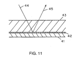
- FIG. 11 A sectional view of a reflecting film used in a conventional film mirror is shown in Fig. 11.
- the reflecting film used in a conventional film mirror is composed of ordinary transparent film 43, on which a metal thin film 42 is evaporated, and the metal surface of the transparent film side is used as the reflecting surface (this mirror is called a back side mirror because the light transmits through the film 43 which is a support member of the reflecting surface).
- a metal thin film of high weather resistance is formed, or a resin-made protective film 41 is formed. That is, the front surface of the metal thin film 42 is a transparent film 43 as the base, and projective means 41 for assuring weather resistance or the like is provided on the rear surface.
- an incident light 44 enters the transparent film 43, and is reflected by the metal thin film, and the reflected light 45 passes again through the transparent film 43 and exits.
- Fig. 12 shows an orientation state of a material of transparent film as the base in the prior art.
- a wide and long polyester film 46 or the like is used for the transparent film material as the base.
- This polyester film 46 is usually exposed to stretching, more or less, in the manufacturing process of the polyester film 46.
- high molecules in the film produce an orientation 47 in the longitudinal direction and width direction of the film.
- the film comes to have an anisotropy of rays for causing birefringence of rays.
- the reflection is complicated. Birefringence is known to differ in the refractive index of abnormal light when the incident direction is different.
- the refractive index differs depending on the wavelength of the incident light.
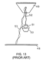
- Fig. 13 shows a configuration of electronic parts of a liquid crystal projection type image magnifying apparatus in the prior art.
- the image delivered from a liquid crystal projector 50 is projected by a liquid crystal projector projecting lens 51, reflected by a mirror 49, and magnified and projected on a screen 48.
- the ray of light passing through the liquid crystal panel and projected from the projector is polarized, either p polarized light or s polarized light.
- the ray of light converged on one spot on the screen is the polarized light emitted from the liquid crystal projector being reflected in a wide range of the mirror.
- the imaging on the screen is a synthesis of polarized lights for producing the axes of polarization mutually different in a wide range of mirror, which is a synthesis of complicated images differing in each colour.
- the projected image 56 on the screen 48 is coloured, or separated into rainbow colours.
- a film mirror as disclosed in Japanese Laid-open Patent No. 4-339642, it is a back side mirror using the ordinary PET film side as mirror, and the above problems occur.
- colour deviation may occur on the screen, rainbow colours may appear, moire stripes may be formed, or double images or multiple images may be formed.
- the light is reflected not only on the metal thin film, but also on the PET film surface. Still more, since the PET film has an important role as a support member, it cannot be made too thin, and hence the image appears to be double or multiple images, and the picture quality deteriorates.
- the conventional film mirror is not suited to the reflecting mirror for liquid crystal projection type image magnifying apparatus.
- the invention provides a reflecting film having resin layers on both sides of a metal thin film, in which at least one of the resin layers is colourless, transparent, and optically isotropic, and the metal thin film at the side of colourless, transparent and optically isotropic resin layer is used as the reflecting surface.
- the other resin layer is protective means for assuring weather resistance for projecting the metal thin film and supporting means for supporting the metal thin film.
- the mirror using this reflecting film is free from optical anisotropy, and hence problems due to conventional complicated refraction are solved.
- the invention is realized by applying the discovery of the fact that the film formed of a resin dissolved in organic solvent by printing method (hereinafter called coat layer) is free from optical anisotropy and is optically isotropic.
- a metal film is formed on a base film, and materials mentioned in the embodiment are formed by printing or other method. That is, in the case of resin film by printing, it has no optical anisotropy, and the axis of polarization is not rotated.
- the metal thin film playing the role of reflecting surface is coated with the resin, and the light enters and reflects through this coat layer. Therefore, it is a mode of face side mirror.
- the transmissivity of the coat layer of film mirror of face side mirror is extremely high as compared with that of the back side mirror having the stretched base film side as the reflecting surface of conventional type.
- the reason is the thickness of coat layer may be made sufficiently thinner than the base film, and the degree of freedom of selection of material of the coat layer is high, and a material of high transmissivity can be selected. Therefore, since the transmissivity of the coat layer is so high, the reflectivity of the face side mirror is higher than the reflectivity of the back side mirror.
- the thin coat layer if a double image is formed, it is less obvious visibly, and practically troubles of double or multiple images will not occur.
- Fig. 1 is a sectional view of a basic composition of a reflecting film of the invention.
- Fig. 2 is a sectional view of a reflecting film in embodiment 1 thereof.
- Fig. 3A is a sectional view of a reflecting film in embodiment 2 thereof.
- Fig. 3B is a sectional view of a reflecting film in embodiment 3 thereof.
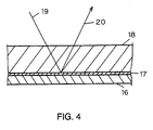
- Fig. 4 is a sectional view of a reflecting film in embodiment 4 thereof.
- Fig. 5A is a side view of a mirror in embodiment 5 thereof.
- Fig. 5B is a perspective view of the mirror in embodiment 5 thereof.
- Fig. 6 is a CRT projection type image magnifying apparatus using the mirror of the invention.
- Fig. 7 is a liquid crystal projection type image magnifying apparatus using the mirror of the invention.
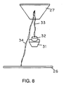
- Fig. 8 is optical parts layout 1 of the liquid crystal projection type image magnifying apparatus in embodiment 5.
- Fig. 9 is optical parts layout 2 of the liquid crystal projection type image magnifying apparatus in embodiment 5.
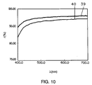
- Fig. 10 is a diagram of reflectivity of ray of light of the reflecting films in embodiments 1, 2, 3, and 4.
- Fig. 11 is a sectional view of a transparent film used in a film mirror in prior art.
- Fig. 12 is a diagram of orientation state of film material of the base in prior art.
- Fig. 13 is optical parts layout 1 of the liquid crystal projection type image magnifying apparatus in prior art.
- Fig. 14 is optical parts layout 2 of the liquid crystal projection type image magnifying apparatus in prior art.
- Fig. 1 is a sectional view of a basic composition of a reflecting film of the invention.
- Resin layers 1, 3 are provided on both sides of a metal thin film 2.
- the one resin layer 1 is colourless, transparent, and optically isotropic, and a mirror is composed by using its metal thin film as the reflecting surface.
- the role of the other resin layer 3 not used as the reflecting surface of the metal thin film is to protect the metal thin film, and its material may be either same as or different from the resin of the reflecting surface side.
- a reflecting film of a first exemplary embodiment of the invention is described by referring to a sectional view in Fig. 2.
- a metal thin film 5 is formed on a resin film 4 used as the base, and a resin transparent coat layer 6 is formed thereon. From this coated-form coat layer, an incident light 7 enters. and a reflected light 8 is reflected on the metal thin film 5.
- the base resin film 4 is a 25 ⁇ m thick PET film.
- the thickness is proper in a range of 10 to 100 ⁇ m from the viewpoint of ease of lining with a film, if lining, but the base may be as thick as about 300 ⁇ m in a special case. Meanwhile, if the smoothness and uniformity of the surface are extremely important, it is required to use a film not containing granular ultraviolet ray absorbent, lubricant, or other solid matter that may undulate the film surface.
- a thin layer of Ag (silver) was formed as the metal thin film 5 in a thickness of about 100nm by resistance heating type continuous deposition.
- a proper thickness of Ag is about 50nm to 300nm. If less than 50nm, the ray reflectivity deteriorates below 80%, and the basic performance as mirror cannot be achieved. If exceeding 300nm, the film is too tenacious to work smoothly, and obvious folds by wrinkles are likely to be formed. Besides, the cost is increased.
- a colourless and transparent resin coat layer 6 was formed by gravure coating method. Using resins of thermoplastic polyester system and thermosetting epoxy-melamine system, a small amount of isocyanate was mixed. They were dissolved in a mixed solvent of methyl ethyl ketone (MEK), butyl acetate, and butyl cellosolve. The heating and curing process after forming the coat film was conducted at 170°C for 5 minutes.
- MEK methyl ethyl ketone
- the thickness of the cured coat layer is 3 ⁇ m. This thickness is necessary for preventing oxidation and sulfurisation of metal thin film, and it sufficiently satisfies the purpose of protection of surface.
- the resin film formed by this coat layer shows an optical isotropy. The transparency of this coat film is extremely high, and the transmissivity is over 98%.
- the coat layer is composed of polyester system and epoxy-melamine system, but it may be also formed of thermosetting acrylic system, UV curing type polyester system, acrylic system, or epoxy system. As far as it is colourless and transparent and over 97% in transmissivity at coat film thickness of scores of ⁇ m, any material can be used.
- a reflecting film in a second exemplary embodiment of the invention is described by referring to sectional views in Fig. 3A and Fig. 3B.
- a metal thin film 10 is formed on a base resin film 9, and a first layer 13 of the coat layer is formed thereon, and a second layer 14 of the coat layer is further formed thereon.
- An incident light 11 enters from the coated surface of two layers of resin in a film form, and transmits through the coat layers 14, 13, and is reflected by the metal thin film 10, and passes again through the coat layers 13, 14, and a reflected light 12 is reflected.
- the base resin film 9 was a 25 ⁇ m thick PET film. Thereon, a thin layer of Ag was formed as the metal thin film 10 in a thickness of about 100nm by resistance heating type continuous deposition.
- a first layer 13 of a colourless and transparent resin coat layer was formed by gravure coating method.
- resins of thermoplastic polyester system and thermosetting epoxy-melamine system a small amount of isocyanate was mixed. They were dissolved in a mixed solvent of methyl ethyl ketone (MEK), butyl acetate, and butyl cellosolve.
- MEK methyl ethyl ketone
- the heating and curing process after forming the coat film was conducted at 170°C for 5 minutes.
- the thickness of the cured coat layer is 0.3 microns. This thickness is a minimum requirement for preventing oxidation and sulfurisation of Ag immediately after deposition of Ag.
- the transparency of this coat film is extremely high, and the transmissivity is over 98%.
- a second layer of coat layer 14 was formed.
- an acrylic resin and isocyanate were dissolved in the same solvent.
- This solution was printed by reverse coating method suited to application in a relatively uniform thickness.
- this layer was checked for coat film defects such as pin holes by salt spray test.
- a cycle of 16 hr of salt spray and 8 hr of no spray was repeated.
- a reflecting film of a third exemplary embodiment of the invention is described by referring to the sectional view in Fig. 3B.
- a third coat layer 15 is further formed on the film of the second exemplary embodiment in Fig. 3A.
- the material of the third coat layer 15 is same as that of the second layer 14 of the coat layers.
- the total thickness of three coat layers 13, 14, 15 is 5 microns. In particular, when used in severe environments, the reliability of environmental resistance can be further enhanced.
- Fig. 10 shows the difference in reflectivity between the Ag thin film and Al thin film, and proves that the reflectivity 40 of Al is inferior to the reflectivity 39 of Ag.
- PET films are used, but it is not necessary to be transparent and any colour may be used. Not limited to PET, polycarbonate, polybutylene terephthalate, PEN, and others may be used, as far as they are free from solid matter causing undulations of the film such as granular ultraviolet ray absorbent and lubricant, smooth in surface, durable to withstand curing temperature of coat, and stable for a long period to endure specific tension.
- resistance heating type continuous deposition is shown, but it may be similarly formed by other methods, including induction heating method, electron beam heating method, other continuos deposition method, and sputter continuous deposition method, among others.
- coat material resins of thermoplastic polyester system and thermosetting epoxy-melamine system, and resins of isocyanate and acrylic system are shown, but any other resins may be used as far as the ray transmissivity of the coat film alone is over 95% at coat film thickness of several microns, and the weather resistance is excellent. Or these resins may be properly mixed.
- Fig. 4 is a sectional view of a fourth exemplary embodiment of reflecting film.
- the first to third embodiments refer to the face side mirror, while the fourth embodiment represents the back side mirror.
- a thin film 17 of Ag was formed in a thickness of 100nm same as in the first to third embodiments.
- a protective film or coat 16 was formed by printing for the purpose of surface protection and weather resistance of the metal thin film 17.
- the PET film side is used as the reflecting surface.
- An incident light 19 transmits through PET film 18, and is reflected by the metal thin film 17, and passes again through the PET film 18, and a reflected light 20 is reflected.
- PET as the material for the film
- other material may be used as far as the film material is free from orientation in the high molecules, not stretched in the manufacturing process, colourless and transparent, and optically isotropic.
- the reflecting films explained in the first to fourth embodiments were adhered by using an adhesive (Konishi G5800 rubber adhesive, in a thickness of about 10 ⁇ m), with a tension applied to the side (film adhering portion) 23 of an aluminum frame 21 as shown in Fig. 5A.
- the reflecting films were turned to the back side of the aluminum frame 21, and the end portions of the reflecting films were adhered by using an adhesive tape 24.
- the reflecting film is defined in height by a rib 25 of 2 mm in height and 3 mm in thickness provided on the outer circumference of the aluminum frame 21, and the whole circumference of the aluminum frame is an effective area of mirror.
- This rib 25 has a curvature for the ease of sliding when lining with the reflecting film 22.
- a perspective view of thus manufactured mirror is shown in Fig. 5B.
- a pressure of 30 g/cm2 is applied in a disk of 25 mm in diameter in the central part, at ordinary temperature, in the case of a trapezoidal frame measuring 690 mm in upper bottom, 960 mm in lower bottom, and 520 mm in height, and sinking is measured.
- the sinking value at ordinary temperature is in a range of 3 mm to 7 mm.
- the aluminum frame is drawn out continuously from a die in a sectional shape as shown in Fig. 5A, and is manufactured into a long square member. It is cut in a specific length in a oblique cut section, and butts are joined, welded, and a trapezoidal aluminum frame 21 is prepared.
- the required flatness is 1 mm or less when placed on a surface plate with the rib 25 downward.
- the image of a liquid crystal projector 31 was reflected as shown in Fig. 9, and the image was projected on a transmission type screen 26.
- the reflected image 38 was a very sharp image free from rainbow blurring or moire.
- the axis of polarization of the incident projected light 33 leaving the liquid crystal projector 31 is identical with the axis of polarization of the reflected light 34. That is, the angle of axis of polarization is not changed by mirror reflection.
- Fig. 7 shows a 48-inch liquid crystal projection type image magnifying apparatus.
- reference numeral 26 is a screen
- 27 is a mirror
- 30 is a housing or main body
- 31 is a liquid crystal projector
- 32 is a liquid crystal projector projection lens.
- Fig. 6 shows a 48-inch CRT projection type image magnifying apparatus.
- reference numeral 26 is a screen
- 27 is a mirror
- 30 is a housing
- 29 is a CRT projector
- 28 is a projection lens.
- the mirror of the invention was installed in the 48-inch projection type image magnifying apparatus as shown in Fig. 6 and Fig. 7, a specified image pattern was displayed, the luminance in the black display area and white display area was measured, and the ratio was determined.
- the ratio of white luminance to black luminance is called the contrast.
- the mirror of the invention indicated 38.2 as compared with 34.5 of the conventional mirror. Hence, it was confirmed that the contrast was improved about 10%.
- the method of installing the mirror in the aluminum frame is not limited to the illustrated method.
- the film mirror may be fixed to the top or back of the frame by means of an adhesive, or instead of using adhesive, the reflecting film may be fastened to the frame by using a metal frame as if stretching a drumhead over an end of a cylinder.
- the frame material is not limited to aluminum, but lightweight metal such as Ti and Ni, or resin may be used, and it may be also realized by any other lightweight and rigid material such as polymer alloy and polymer containing glass fiber.
Landscapes
- Physics & Mathematics (AREA)
- General Physics & Mathematics (AREA)
- Optics & Photonics (AREA)
- Engineering & Computer Science (AREA)
- Multimedia (AREA)
- Signal Processing (AREA)
- Optical Elements Other Than Lenses (AREA)
- Projection Apparatus (AREA)
- Transforming Electric Information Into Light Information (AREA)
- Laminated Bodies (AREA)
Applications Claiming Priority (3)
| Application Number | Priority Date | Filing Date | Title |
|---|---|---|---|
| JP122953/96 | 1996-05-17 | ||
| JP12295396 | 1996-05-17 | ||
| JP8122953A JPH09311207A (ja) | 1996-05-17 | 1996-05-17 | ミラーとフィルムとテレビジョン受像機 |
Publications (3)
| Publication Number | Publication Date |
|---|---|
| EP0807833A2 true EP0807833A2 (fr) | 1997-11-19 |
| EP0807833A3 EP0807833A3 (fr) | 1998-07-22 |
| EP0807833B1 EP0807833B1 (fr) | 2002-07-24 |
Family
ID=14848718
Family Applications (1)
| Application Number | Title | Priority Date | Filing Date |
|---|---|---|---|
| EP97303344A Expired - Lifetime EP0807833B1 (fr) | 1996-05-17 | 1997-05-16 | Miroir et film réfléchissants et récepteur de télévision |
Country Status (7)
| Country | Link |
|---|---|
| US (3) | US6203162B1 (fr) |
| EP (1) | EP0807833B1 (fr) |
| JP (1) | JPH09311207A (fr) |
| KR (1) | KR100215587B1 (fr) |
| CN (1) | CN1245831C (fr) |
| DE (1) | DE69714137T2 (fr) |
| MY (1) | MY118878A (fr) |
Cited By (1)
| Publication number | Priority date | Publication date | Assignee | Title |
|---|---|---|---|---|
| US6035596A (en) * | 1998-05-14 | 2000-03-14 | Technoform Caprano + Brunnhofer Ohg | Heat-insulating connecting profile with IR-blocking foil |
Families Citing this family (18)
| Publication number | Priority date | Publication date | Assignee | Title |
|---|---|---|---|---|
| JPH09311207A (ja) * | 1996-05-17 | 1997-12-02 | Matsushita Electric Ind Co Ltd | ミラーとフィルムとテレビジョン受像機 |
| US20050174645A1 (en) * | 2002-04-23 | 2005-08-11 | Magna Donnelly Mirrors North America | Vehicle mirror having polymeric reflective film element and self-dimming element |
| US7399093B2 (en) * | 2002-09-19 | 2008-07-15 | Lg Electronics Inc. | Reflection mirror of projection television and fabrication method thereof |
| JP2004325694A (ja) | 2003-04-24 | 2004-11-18 | Hitachi Ltd | 背面反射鏡およびそれを用いた背面投写型映像表示装置 |
| JP2005326434A (ja) | 2004-05-12 | 2005-11-24 | Hitachi Ltd | 反射ミラー及びそれを用いた背面投射型映像表示装置 |
| KR100664318B1 (ko) * | 2005-01-07 | 2007-01-04 | 삼성전자주식회사 | 프로젝션 tv |
| JP2006337770A (ja) * | 2005-06-02 | 2006-12-14 | Central Glass Co Ltd | 表面鏡 |
| US7853414B2 (en) * | 2005-11-23 | 2010-12-14 | Electric Mirror, Llc | Mounting structure for a mirror assembly |
| US8099247B2 (en) * | 2005-11-23 | 2012-01-17 | Electric Mirror, Llc | Back lit mirror with media display device |
| TWI358575B (en) * | 2006-03-17 | 2012-02-21 | Light diffusion reflection sheet with buffering ef | |
| CN102116884B (zh) * | 2006-06-30 | 2012-10-10 | 日本板硝子株式会社 | 反射镜和反射镜用玻璃基板 |
| JP5660051B2 (ja) * | 2009-12-21 | 2015-01-28 | コニカミノルタ株式会社 | フィルムミラー、その製造方法、それを用いた太陽熱発電用反射装置 |
| GB201003887D0 (en) | 2010-03-09 | 2010-05-12 | British American Tobacco Co | Methods for extracting and isolating constituents of cellulosic material |
| CN102455451A (zh) * | 2011-04-29 | 2012-05-16 | 昆山市诚泰电气股份有限公司 | 反射片 |
| DE102012100293A1 (de) * | 2012-01-13 | 2013-07-18 | Hydro Aluminium Rolled Products Gmbh | Kantenversiegelter Spiegel und Verfahren zu dessen Herstellung |
| JP6029486B2 (ja) * | 2013-02-21 | 2016-11-24 | 富士フイルム株式会社 | 太陽光集光用反射鏡 |
| CN103123401A (zh) * | 2013-03-20 | 2013-05-29 | 台玻悦达太阳能镜板有限公司 | 一种新型太阳能反射镜及其制造工艺 |
| NL2012607B1 (nl) * | 2014-04-11 | 2016-05-09 | Aviation Glass & Tech Holding B V | Voertuigspiegel, en werkwijze ter vervaardiging van een dergelijke spiegel. |
Family Cites Families (18)
| Publication number | Priority date | Publication date | Assignee | Title |
|---|---|---|---|---|
| JPS5720718A (en) * | 1980-07-11 | 1982-02-03 | Toyobo Co Ltd | Polarizing plate with transparent conductive layer |
| US4543485A (en) * | 1981-11-24 | 1985-09-24 | Hitachi Chemical Company, Ltd. | Scintillator for radiation detection and process for producing the same |
| JPS58125084A (ja) * | 1982-01-21 | 1983-07-25 | 株式会社東芝 | 液晶表示装置およびその製造方法 |
| JPS615986A (ja) | 1984-06-20 | 1986-01-11 | Mitsui Toatsu Chem Inc | 光記録媒体 |
| US4731155A (en) * | 1987-04-15 | 1988-03-15 | General Electric Company | Process for forming a lithographic mask |
| JP2545253B2 (ja) * | 1987-12-19 | 1996-10-16 | 藤森工業株式会社 | 光カードの光記録層保護用積層体 |
| JPH0723762Y2 (ja) * | 1988-12-07 | 1995-05-31 | パイオニア株式会社 | プロジェクションテレビの反射部材 |
| JPH05100107A (ja) * | 1991-04-19 | 1993-04-23 | Konica Corp | 反射ミラー |
| JP3048253B2 (ja) | 1991-05-17 | 2000-06-05 | 三井化学株式会社 | 反射体 |
| JPH05273405A (ja) * | 1992-03-25 | 1993-10-22 | Hitachi Ltd | 反射鏡 |
| US5247395A (en) | 1992-05-11 | 1993-09-21 | Eugene Martinez | Thin film mirror |
| JPH0669901U (ja) * | 1993-03-05 | 1994-09-30 | 株式会社村上開明堂 | プロジェクション方式テレビ用反射鏡 |
| US5506642A (en) | 1993-12-20 | 1996-04-09 | Fujitsu Limited | Projector with plastic mirror |
| JP3447132B2 (ja) | 1993-12-20 | 2003-09-16 | 富士通株式会社 | プロジェクター |
| EP0784066B1 (fr) | 1994-09-30 | 2002-01-16 | Nippon Zeon Co., Ltd. | Polymere a ouverture de cycle hydrogene |
| US5699188A (en) * | 1995-06-26 | 1997-12-16 | Minnesota Mining And Manufacturing Co. | Metal-coated multilayer mirror |
| JP3686137B2 (ja) * | 1995-09-07 | 2005-08-24 | 旭化成ケミカルズ株式会社 | 反射鏡 |
| JPH09311207A (ja) * | 1996-05-17 | 1997-12-02 | Matsushita Electric Ind Co Ltd | ミラーとフィルムとテレビジョン受像機 |
-
1996
- 1996-05-17 JP JP8122953A patent/JPH09311207A/ja active Pending
-
1997
- 1997-05-16 CN CNB971131406A patent/CN1245831C/zh not_active Expired - Fee Related
- 1997-05-16 EP EP97303344A patent/EP0807833B1/fr not_active Expired - Lifetime
- 1997-05-16 DE DE69714137T patent/DE69714137T2/de not_active Expired - Fee Related
- 1997-05-16 KR KR1019970018980A patent/KR100215587B1/ko not_active Expired - Fee Related
- 1997-05-16 US US08/857,913 patent/US6203162B1/en not_active Expired - Fee Related
- 1997-05-17 MY MYPI97002161A patent/MY118878A/en unknown
-
2000
- 2000-10-26 US US09/696,783 patent/US6264341B1/en not_active Expired - Fee Related
-
2001
- 2001-06-29 US US09/896,440 patent/US6425672B2/en not_active Expired - Fee Related
Cited By (1)
| Publication number | Priority date | Publication date | Assignee | Title |
|---|---|---|---|---|
| US6035596A (en) * | 1998-05-14 | 2000-03-14 | Technoform Caprano + Brunnhofer Ohg | Heat-insulating connecting profile with IR-blocking foil |
Also Published As
| Publication number | Publication date |
|---|---|
| EP0807833B1 (fr) | 2002-07-24 |
| CN1166753A (zh) | 1997-12-03 |
| US20010038505A1 (en) | 2001-11-08 |
| US6264341B1 (en) | 2001-07-24 |
| US6425672B2 (en) | 2002-07-30 |
| DE69714137T2 (de) | 2002-11-07 |
| EP0807833A3 (fr) | 1998-07-22 |
| KR970073953A (ko) | 1997-12-10 |
| CN1245831C (zh) | 2006-03-15 |
| US6203162B1 (en) | 2001-03-20 |
| MY118878A (en) | 2005-02-28 |
| JPH09311207A (ja) | 1997-12-02 |
| DE69714137D1 (de) | 2002-08-29 |
| KR100215587B1 (ko) | 1999-08-16 |
Similar Documents
| Publication | Publication Date | Title |
|---|---|---|
| EP0807833B1 (fr) | Miroir et film réfléchissants et récepteur de télévision | |
| US6091469A (en) | Light reflector for use in a reflective-type liquid-crystal display | |
| US6111699A (en) | Light diffusing film and its manufacture, a polarizing plate with a light diffusing layer, and a liquid crystal display apparatus | |
| US7262911B2 (en) | Reflex-type screen assembly | |
| EP0911654B1 (fr) | Feuille lenticulaire et procédé pour sa fabrication | |
| JPH09114003A (ja) | プロジェクションスクリーン | |
| JP2003131326A (ja) | 透過型スクリーン | |
| US6233095B1 (en) | Screen member for a reflex type screen | |
| JPH04367838A (ja) | 反射型映写スクリーン | |
| JPH09211729A (ja) | 反射型スクリーン | |
| JPH1195326A (ja) | プロジェクションスクリーン用レンチキュラーシート | |
| KR100940762B1 (ko) | 배면 투사형 스크린용 광확산 시트 및 이를 이용한 배면 투사형 스크린 | |
| JPH07113681B2 (ja) | 反射防止光学フイルタ− | |
| KR100945753B1 (ko) | 투사형 스크린 | |
| JP2013156373A (ja) | 反射スクリーンの製造方法 | |
| JP3870449B2 (ja) | 反射防止層付き偏光板 | |
| KR200392336Y1 (ko) | 투사형 스크린 | |
| JP2006163165A (ja) | 反射型の投影スクリーンを備えた投影システム | |
| KR100940763B1 (ko) | 투사형 스크린 | |
| JPH11248908A (ja) | 平面型レンズ | |
| KR20070063116A (ko) | 투사형 스크린 | |
| JP3489298B2 (ja) | 明室用反射型スクリーン | |
| JP2970390B2 (ja) | 反射型スクリーン | |
| KR20060033954A (ko) | 투사형 스크린 | |
| JPH0728170A (ja) | 透過型投影スクリーンとその製造方法 |
Legal Events
| Date | Code | Title | Description |
|---|---|---|---|
| PUAI | Public reference made under article 153(3) epc to a published international application that has entered the european phase |
Free format text: ORIGINAL CODE: 0009012 |
|
| AK | Designated contracting states |
Kind code of ref document: A2 Designated state(s): DE GB |
|
| PUAL | Search report despatched |
Free format text: ORIGINAL CODE: 0009013 |
|
| AK | Designated contracting states |
Kind code of ref document: A3 Designated state(s): DE GB |
|
| 17P | Request for examination filed |
Effective date: 19980907 |
|
| 17Q | First examination report despatched |
Effective date: 20000510 |
|
| GRAG | Despatch of communication of intention to grant |
Free format text: ORIGINAL CODE: EPIDOS AGRA |
|
| RAP1 | Party data changed (applicant data changed or rights of an application transferred) |
Owner name: MATSUSHITA ELECTRIC INDUSTRIAL CO., LTD. |
|
| GRAG | Despatch of communication of intention to grant |
Free format text: ORIGINAL CODE: EPIDOS AGRA |
|
| GRAH | Despatch of communication of intention to grant a patent |
Free format text: ORIGINAL CODE: EPIDOS IGRA |
|
| GRAH | Despatch of communication of intention to grant a patent |
Free format text: ORIGINAL CODE: EPIDOS IGRA |
|
| GRAA | (expected) grant |
Free format text: ORIGINAL CODE: 0009210 |
|
| AK | Designated contracting states |
Kind code of ref document: B1 Designated state(s): DE GB |
|
| REG | Reference to a national code |
Ref country code: GB Ref legal event code: FG4D |
|
| REF | Corresponds to: |
Ref document number: 69714137 Country of ref document: DE Date of ref document: 20020829 |
|
| PLBE | No opposition filed within time limit |
Free format text: ORIGINAL CODE: 0009261 |
|
| STAA | Information on the status of an ep patent application or granted ep patent |
Free format text: STATUS: NO OPPOSITION FILED WITHIN TIME LIMIT |
|
| 26N | No opposition filed |
Effective date: 20030425 |
|
| PGFP | Annual fee paid to national office [announced via postgrant information from national office to epo] |
Ref country code: DE Payment date: 20070510 Year of fee payment: 11 |
|
| PGFP | Annual fee paid to national office [announced via postgrant information from national office to epo] |
Ref country code: GB Payment date: 20070516 Year of fee payment: 11 |
|
| GBPC | Gb: european patent ceased through non-payment of renewal fee |
Effective date: 20080516 |
|
| PG25 | Lapsed in a contracting state [announced via postgrant information from national office to epo] |
Ref country code: DE Free format text: LAPSE BECAUSE OF NON-PAYMENT OF DUE FEES Effective date: 20081202 |
|
| PG25 | Lapsed in a contracting state [announced via postgrant information from national office to epo] |
Ref country code: GB Free format text: LAPSE BECAUSE OF NON-PAYMENT OF DUE FEES Effective date: 20080516 |