EP0807799B1 - Abtastgerät für eine Sonde - Google Patents
Abtastgerät für eine Sonde Download PDFInfo
- Publication number
- EP0807799B1 EP0807799B1 EP97107827A EP97107827A EP0807799B1 EP 0807799 B1 EP0807799 B1 EP 0807799B1 EP 97107827 A EP97107827 A EP 97107827A EP 97107827 A EP97107827 A EP 97107827A EP 0807799 B1 EP0807799 B1 EP 0807799B1
- Authority
- EP
- European Patent Office
- Prior art keywords
- probe
- tube portion
- scanning apparatus
- scanning
- viscous element
- Prior art date
- Legal status (The legal status is an assumption and is not a legal conclusion. Google has not performed a legal analysis and makes no representation as to the accuracy of the status listed.)
- Expired - Lifetime
Links
- 239000000523 sample Substances 0.000 title claims description 126
- 238000006073 displacement reaction Methods 0.000 claims description 23
- 238000010438 heat treatment Methods 0.000 claims description 12
- 230000008018 melting Effects 0.000 claims description 7
- 238000002844 melting Methods 0.000 claims description 7
- 230000000704 physical effect Effects 0.000 claims description 4
- 239000013013 elastic material Substances 0.000 claims description 3
- 230000003213 activating effect Effects 0.000 claims 2
- 230000007246 mechanism Effects 0.000 description 20
- 238000010276 construction Methods 0.000 description 10
- 238000010586 diagram Methods 0.000 description 10
- 230000000694 effects Effects 0.000 description 8
- 230000010354 integration Effects 0.000 description 7
- LYCAIKOWRPUZTN-UHFFFAOYSA-N Ethylene glycol Chemical compound OCCO LYCAIKOWRPUZTN-UHFFFAOYSA-N 0.000 description 4
- 239000012528 membrane Substances 0.000 description 4
- 229920000642 polymer Polymers 0.000 description 3
- WGCNASOHLSPBMP-UHFFFAOYSA-N hydroxyacetaldehyde Natural products OCC=O WGCNASOHLSPBMP-UHFFFAOYSA-N 0.000 description 2
- 238000000034 method Methods 0.000 description 2
- XNGIFLGASWRNHJ-UHFFFAOYSA-L phthalate(2-) Chemical compound [O-]C(=O)C1=CC=CC=C1C([O-])=O XNGIFLGASWRNHJ-UHFFFAOYSA-L 0.000 description 2
- 230000003746 surface roughness Effects 0.000 description 2
- 238000013459 approach Methods 0.000 description 1
- 238000005452 bending Methods 0.000 description 1
- 238000007689 inspection Methods 0.000 description 1
- 239000000463 material Substances 0.000 description 1
- 238000005457 optimization Methods 0.000 description 1
- 239000004065 semiconductor Substances 0.000 description 1
- 239000007787 solid Substances 0.000 description 1
- 238000007711 solidification Methods 0.000 description 1
- 230000008023 solidification Effects 0.000 description 1
Images


Classifications
-
- G—PHYSICS
- G01—MEASURING; TESTING
- G01Q—SCANNING-PROBE TECHNIQUES OR APPARATUS; APPLICATIONS OF SCANNING-PROBE TECHNIQUES, e.g. SCANNING PROBE MICROSCOPY [SPM]
- G01Q10/00—Scanning or positioning arrangements, i.e. arrangements for actively controlling the movement or position of the probe
- G01Q10/04—Fine scanning or positioning
-
- B—PERFORMING OPERATIONS; TRANSPORTING
- B82—NANOTECHNOLOGY
- B82Y—SPECIFIC USES OR APPLICATIONS OF NANOSTRUCTURES; MEASUREMENT OR ANALYSIS OF NANOSTRUCTURES; MANUFACTURE OR TREATMENT OF NANOSTRUCTURES
- B82Y35/00—Methods or apparatus for measurement or analysis of nanostructures
-
- G—PHYSICS
- G01—MEASURING; TESTING
- G01Q—SCANNING-PROBE TECHNIQUES OR APPARATUS; APPLICATIONS OF SCANNING-PROBE TECHNIQUES, e.g. SCANNING PROBE MICROSCOPY [SPM]
- G01Q10/00—Scanning or positioning arrangements, i.e. arrangements for actively controlling the movement or position of the probe
- G01Q10/02—Coarse scanning or positioning
-
- Y—GENERAL TAGGING OF NEW TECHNOLOGICAL DEVELOPMENTS; GENERAL TAGGING OF CROSS-SECTIONAL TECHNOLOGIES SPANNING OVER SEVERAL SECTIONS OF THE IPC; TECHNICAL SUBJECTS COVERED BY FORMER USPC CROSS-REFERENCE ART COLLECTIONS [XRACs] AND DIGESTS
- Y10—TECHNICAL SUBJECTS COVERED BY FORMER USPC
- Y10S—TECHNICAL SUBJECTS COVERED BY FORMER USPC CROSS-REFERENCE ART COLLECTIONS [XRACs] AND DIGESTS
- Y10S977/00—Nanotechnology
- Y10S977/84—Manufacture, treatment, or detection of nanostructure
- Y10S977/849—Manufacture, treatment, or detection of nanostructure with scanning probe
- Y10S977/86—Scanning probe structure
- Y10S977/872—Positioner
Definitions
- the present invention relates to a probe scanning apparatus for a scanning type probe microscope or the like and, more particularly, to a probe scanning apparatus which is enabled to scan a probe by integrating a mechanism for a z-coarse movement to bring a miniature probe close to a sample surface and for z-fine movement to control the distance between the miniature probe and the sample surface and a mechanism for x- and y-scans to scan the sample surface and which is additionally given a zooming function.
- a scanning type probe microscope of the prior art will be described with reference to Fig. 8.
- a sample bed 51 On the upper face of a cylindrical piezo element 55, there is mounted a sample bed 51. On this sample bed 51, there is placed a sample 52. Over this sample 52, there is oppositely disposed a miniature probe 54 which is carried on the free end of a cantilever 53.
- an electrode 56 On the cylindrical surface of the piezo element 55, there are formed an electrode 56, which is wound around the cylindrical surface for the z-fine movement, and four quarter electrodes 57a, 57b (although not shown), 58a and 58b (although not shown) for the x- and y-scanning operations.
- a pulse motor 60 is given a performance of about 500 angstroms/pulse so that a screw rod 61 is turned to move the piezo element 55 coarsely in the direction z when the pulse motor 60 is activated.
- the warpage of the cantilever 53 is detected by a position detector 73 in terms of a laser beam 72 outputted from a laser generator 71.
- the position detector 73 is composed of four quarter light detecting electrodes and is so positioned that the spot of the laser beam 72 comes to the center of the four quarter electrodes when the warpage of the cantilever 53 is 0.
- the spot of the laser beam 72 moves over the four quarter electrodes so that a difference is made among the voltages outputted from the four quarter electrodes.
- These voltages are amplified by an amplifier 74 and inputted to a differential amplifier 75.
- the inverted input terminal (-) of this amplifier 74 is set with a reference value of the warpage of the cantilever so that the output of the differential amplifier 75 is 0 when the warpage is 0, for example.
- the differential output of the differential amplifier 75 is inputted to an integration circuit 76 and a proportional circuit 77 so that the difference is averaged in the integration circuit 76 whereas its high-frequency component is extracted in the proportional circuit 77.
- the averaged difference and the high-frequency component are synthesized, and the synthesized output is then amplified by a voltage amplifier 78 until it is applied to the electrode 56.
- the circuit as composed of the position detector 73, the amplifier 74, the differential amplifier 75, the integration circuit 76, the proportional circuit 77 and the voltage amplifier 78, constructs a feedback circuit.
- a CRT 80 receives the x- and y-direction scanning signals from a raster scanner 81 and the warpage signal of the cantilever 53 from a line 82 so that it displays either the shape of the surface of the sample 52 or the physical properties on the display.
- the z-coarse movement is effected by the pulse motor 60 and the screw rod 61; the z-fine movement is effected by applying the feedback signal to the cylindrical electrode 56 on the piezo element 55; and the x- and y-scans are effected by applying the x- and y-scanning signals, as outputted from the raster scanner 81, to the four quarter electrodes 57a, 57b, 58a and 58b.
- the relation i.e., the applied voltage - displacement characteristics
- the voltage, as applied to the electrode of the piezo element, and the displacement of the same is non-linear to cause a problem that the displacement cannot be enlarged.
- a voltage as high as several hundreds to one thousand volts has to be applied to the electrode. This makes it necessary to shield the periphery and to provide a protection circuit for dropping the voltage when the apparatus is opened. This raises a problem that the apparatus is difficult to handle.
- a further probe scanning apparatus comprising the features recited in the preamble of present claim 1, is disclosed in WO-A-96/07074.
- An object of the present invention is to eliminate the above-specified problems of the prior art and to provide a probe scanning apparatus of simple construction, in which z-direction coarse/fine mechanisms and x- and y-scanning mechanisms are integrated and which is provided with a zooming function.
- a probe scanning apparatus is recited in present claim 1.
- a probe scanning apparatus to be used in a device for measuring the shape of the surface or the physical properties of a sample by bringing the probe close to the sample surface, which apparatus comprises: voice coil motors arranged in three directions x, y and z; probe supporting means to be moved in the three directions x, y and z by the forces coming from the voice coil motors; and zooming means for realizing a zooming function by limiting the moving range of the probe supporting means.
- the probe can be moved coarsely/finely in the direction z and scanned in the directions x and y by the voice coil motors in the three directions x, y and z, as integrated in the casing. As a result, it is possible to solve all the problems owned by the piezo scanner of the prior art and to scan the probe.
- Any region in the range to be scanned by the probe supporting means can be zoomed. As a result, there can be achieved an excellent effect that any position of the sample surface can be measured in an enlarged scale.
- Fig. 1 is a diagram showing a construction of a probe scanning apparatus according to one embodiment of the present invention.
- a magnet 2 is fixed in a casing 1, and a moving element 4 is loosely fitted on a core rod 3 of the magnet 2.
- the moving element 4 is elastically supported in the casing 1 by a membrane 5, and a coil is wound around the moving element 4.
- Those magnet 2, core rod 3, moving element 4, membrane 5 and coil 6 constitute together a voice coil motor, as used in a speaker or the like.
- a fine wire 7 On the moving element 4, there is fixed one end portion of a fine wire 7, the other end portion of which is fixed at one end of a spindle 8 extending in a direction z. On the other end of this spindle 8, there is fixed a displacement detector 9, on which is mounted a probe 10 such as a cantilever. Moreover, the spindle 8 is supported by an intermediate cylinder 13 at its central portion through a first spring 11 and at its lower end portion through a second spring 12. These first and second springs 11 and 12 are constructed, as shown at (a) and (b) in Fig. 2, of a cross-shaped or ordinary leaf spring disposed in the intermediate cylinder 13. Incidentally, the fine wire 7 acts to absorb the strain of the spindle 8, as caused with respect to the moving element 4 when the spindle 8 is scanned in directions x and y, as will be described hereinafter.
- the casing 1 is equipped with a thinner tube portion 14 protruding into the sample chamber and a thicker tube portion 15 leading from the thinner tube portion 14, and a heater coil 16 is wound around a portion of the thicker tube portion 15.
- a viscous element 17 which is made of a polymer of glycol phthalate. This viscous element 17 exhibits properties similar to those of a solid at the room temperature but a viscosity when heated by energizing the heater coil 16.
- a second magnet 21, and a moving element 23 is loosely fitted on the core rod 22 of the second magnet 21.
- the moving element 23 is elastically supported by the casing 1 through a membrane 24, and a coil 25 is wound around the moving element 23.
- the other end of the spindle 27 is fixed on the side portion of the thicker tube portion 15.
- Those second magnet 21, core rod 22, moving element 23, membrane 24 and coil 25 constitute together a voice coil motor similar to the foregoing one.
- the voice coil motor acts upon the spindle 27 in the direction x, and a not-shown voice coil motor having a similar construction is disposed in a 90-degree turned position to act upon a spindle in the direction y.
- a sample bed 31 At a position confronting the probe 10, there is disposed a sample bed 31, on which is placed a sample 32 to be detected.
- the sample bed 31 is carried on coarse x-, y- and z-stages 33.
- a zoom device In the vicinity of the second magnet 21, on the other hand, there is disposed a zoom device.
- This zoom device is constructed of a holder 34, a heating coil 35, a viscous element 36 fitted in the holder 34, a leaf spring 37 fixed at its one end on the spindle 27 and embedded at its other end in the viscous element 36, and a clamp unit 38.
- the viscous element 36 may be made of a material similar to that of the foregoing viscous element 17.
- the clamp unit 38 is not always indispensable.
- Fig. 3 is a block diagram showing a schematic construction of a z-coarse/fine circuit and x- and y-scanning circuits, as connected with the probe scanning apparatus of Fig. 1.
- the displacement of the probe 10 such as a warpage of the cantilever
- this detected signal is compared with a reference value coming from a reference value generator 42 by a differential amplifier 41. Since this reference value is equalized to the value outputted from the displacement detector 9 when the distance between the probe 10 and the sample surface takes a predetermined value, the differential amplifier 41 outputs a signal having a magnitude according to a displacement at an instant when the distance between the probe 10 and the sample surface is displaced from the predetermined value.
- the output of the differential amplifier 41 is processed b an integration circuit 43 and a proportional circuit 44 and enters a V-I converter 45.
- This V-I converter 45 converts the inputted voltage into a current and feeds it to the coil 4.
- a raster scanner 46 feeds x- and y-direction scanning signal currents xi and yi, respectively, to the coils 25 and 35 which are wound around the x-direction moving element 23 and the y-direction moving element 34.
- the raster scanner 46 further feeds x- and y-scanning signals to a CRT 47. Inspection data such as the shape or physical properties of the sample surface are fetched from the input side of the V-I converter 45 to the CRT 47.
- the feedback circuit which is composed of the displacement detector 9, the differential amplifier 41, the integration circuit 43, the proportional circuit 44 and the V-I converter 45. Since the distance between the probe 10 and the sample surface is large at first, the difference between the reference value, as outputted from the reference value generator 42, and the detected displacement value from the displacement detector 9 is so that that a high signal voltage is outputted from the differential amplifier 41. This signal voltage is processed by the integration circuit 43 and the proportional circuit 44 and is converted by the V-I converter 45 into an electric current I to flow through the coil 6 wound around the moving element 4.
- the detected displacement value from the displacement detector 9 and the reference value from the reference value generator 42 become substantially equal.
- the signal voltage to be outputted from the differential amplifier 41 approaches zero, and the current I to flow through the coil 6 becomes low so that the z-coarse movement stops.
- the timing for turning off the temperature controller is set either at the stopping time of the z-coarse movement or at a slightly earlier time while considering the remaining heat.
- the z-coarse movement is made by using the feedback circuit.
- the coil 6 may be fed with the current from the constant current power source so that the goal of the z-coarse movement may be detected in terms of the attenuation or warpage of the amplitude of the vibration of the cantilever.
- Fig. 4(a) illustrates the scanning current xi in the direction x
- Fig. 4(b) illustrates the scanning current yi in the direction y
- Fig. 4(c) illustrates the x- and y-scanning regions of the sample surface.
- the reference numeral 32 designates the sample having an x- and y-scanning region 32a.
- the scanning operations in the directions x and y are performed by the identical or similar mechanisms so that they will be described by noting the scanning mechanism in the direction x as their representative one.
- the heating coil 35 is excited by the not-shown temperature controller to soften the viscous element 36.
- the thicker tube portion 15 receives a force F, as shown, at a point 15a of force. Then, the thicker tube portion 15 is deviated in the same direction as that of the force F by the deflection of the thinner tube portion 14. If the current I flows in the positive direction into the coil 25 so that the spindle 27 is pulled rightward of Fig. 1, on the other hand, the thicker tube portion 15 receives the force -F at the force point 15a. Then, the thicker tube portion 15 is deviated in the same direction as that of the force -F by the backward deflection of the thinner tube portion 14.
- the probe 10 When the thicker tube portion 15 is deviated in the direction from -x to +x, the probe 10 is widened in its scanning width and scanned in the direction from -x to +x because the it is connected to the thicker tube portion 15 through the spindle 8, the first and second springs 11 and 12, the intermediate cylinder 13 and the viscous element 17.
- Fig. 5 is a conceptional diagram schematically showing the probe 10 which is attached through the thinner tube portion 14, the thicker tube portion 15 and the intermediate cylinder 13 of Fig. 1. It is assumed that the probe 10 is be disposed at a point 15b of action of Fig. 5.
- letter ⁇ designates the angle of deflection at the force point 15a. It is found from this Formula that the deflection at the action point 15b, i.e., the scanning point is enlarged by (l T - 1)tan ⁇ from the deflection y at the force point 15a.
- Fig. 4 Reverting to Fig. 4, here will be described the x and y-scanning operations. If both the x-scanning current xi and the y-scanning current yi are at 0, the probe 10 indicates one point O on the sample, as shown in Fig. 4(c). If a negative current -I, as illustrated, is added to the x-scanning current xi and the y-scanning current yi, the probe 10 comes at time t1 to a scanning origin (x0, y0) on the sample 32. Letters Ts indicate a queuing time, as required for the probe 10 to change the scanning direction by 180 degrees.
- the probe 10 scans the sample 32 in the direction x and comes at time t2 to a scanning terminal (xn, y0) on the sample 32. In this meanwhile, the probe 10 makes the z-fine movement according to the shape of the surface of the sample 32 so that the information on the shape is outputted from the displacement detector 9.
- the probe For the time period between t2 and t3, the probe continues to scan on the same scanning line as before and returns at time t3 to the scanning origin (x0, y0).
- the information, as obtained from the probe 10 for this flyback period, can be prevented by blanking it from being displayed on the CRT 47.
- the y-scanning current yi drastically increases so that the probe 10 comes to a position (x0, y1).
- the scanning operation in the direction x is started from the position (x0, y1).
- the probe 10 makes the z-fine movement according to the shape of the surface of the sample 32 so that the information on the shape is outputted from the displacement detector 9.
- the inside of the scanning region 32a is sequentially scanned, until the x- and y-scanning operations are ended when the probe 10 comes to a position (xn, yn).
- the feedback circuit moves the probe 10 vertically by the displacement z in accordance with the roughness of the surface of the sample 32 so that the deflection of the probe 10, e.g., the cantilever may be constant.
- the displacement z is proportional to the current I to flow through the voice coil 6, and the displacement x takes a value when the probe 10 traces the surface of the sample 32, so that the surface roughness of the sample 32 is proportional to the current I.
- the surface roughness of the sample 32 can be measured if the current to flow through the voice coil 6 is monitored.
- the linearity at this time is more excellent than that of the piezo scanner of the prior art.
- the z-coarse and z-fine movements and the x- and y-scanning operations can be done so that the present embodiment is easier in handling than and superior in safety to the piezo scanner of the prior art and can enlarge the scanning width.
- the present embodiment realizes the probe scan and has a merit that it can inspect the surface of a sample as large as the semiconductor wafer.
- the thinner tube portion 14 and the thicker tube portion 15 are united with the casing 1 into the integral structure.
- the present invention should not be limited to the structure but can be modified such that the casing 1 and the thinner tube portion 14 are separated to make the thinner tube portion of an elastic material different from that of the casing 1.
- the thinner tube portion may also be composed of a plurality of elastic filaments.
- the x- and y-scanning mechanisms are actuated to move the position 0, as indicated on the sample 32 by the probe 10, as illustrated in Fig. 6, to a position 0' to be measured by the zooming.
- k1 indicates the composed transverse spring constant of the thinner tube portion 14 and the thicker tube portion 15, and letter ⁇ indicates a cantilever enlargement ratio.
- the current as matching the forces F1 and F2, is fed to the coil 25 in the direction x and the not-shown coil in the direction y.
- the heating coil 35 for the zooming operation is turned off to solidify the viscous element 36.
- the leaf spring 37 as fixed at its one end on the spring 27, is firmly fixed at its other end on the holder 34.
- the action, although not shown, in the direction y is similar to that in the direction x.
- the leaf spring 37 has a spring constant Ky in the direction y
- the spring constant Ky is substantially equal to the spring constant k1
- the force for the y-direction spring to act in the direction y is indicated by Fy to -Fy
- the spring constants Kx and Ky of the leaf spring 37 are added to the composed transverse spring constant k1 of the thinner tube portion 14 and the thicker tube portion 15. If, in this state, the x- and y-scanning mechanisms are fed with the scanning currents in the directions X and Y, as shown in Fig. 4, a scanning range 32b is shown at (a) and (b) in Fig. 6, and the measured information of the scanning range 32b is fully displayed in a CRT 80, so that the zoomed (or enlarged) measured information is projected in the CRT 80.
- the force Fx for the spindle 27 to act in the direction x and the displacement of the probe 10 i.e., a scanning width W'x
- Wx' ⁇ 2Fx/(kl + 8Kx)
- the scanning range is 32b', as illustrated in Fig. 6(b), and the measured information of the scanning range 32b' is fully displayed in the CRT 80 so that this CRT projects the measured result enlarged by about nine times.
- the position in which the leaf spring 37 is clamped by the clamp 38 should not be limited to that of one half length.
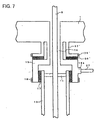
- a heating coil 35', a viscous element 36' and a cylindrical tube 37' are provided in place of the holder 34, the heating coil 35, the viscous element 36, the leaf spring 37 and the clamp unit 38 of Fig. 1.
- the cylindrical tube 37' which leads from or is fixed on the casing 1 at its upper end and which is provided with a seat portion at its lower end; the heating coil 35' is wound around the seat portion; and the viscous element 36' made of glycol phthalate is sandwiched between the thicker tube portion 15 and the cylindrical tube 37'.
- the heating coil 35' is activated by the temperature controller to raise the temperature of the viscous element 36' to a level higher than the melting point.
- the origin O (0, 0) is shifted to the zoom origin O' (x, y), and the heating coil 35' is inactivated by the temperature controller to lower the temperature of the viscous element 36' to a level lower than the melting point.
- the thicker tube portion 15 and the seat portion of the cylindrical tube 37' are firmly fixed by the viscous element 36'.
- the voice coil motors as arranged in the three directions x, y and z, are integrated to move the probe in the three directions x, y and z by their forces.
- the invention has an effect that no consideration is required into safety against a high voltage unlike the piezo scanner of the prior art.
- the probe supporting means of an elastic material is pushed or pulled by the forces coming from the voice coil motors, and another effect is that the x- and y-scans can be achieved over wide ranges by the weak forces. Thanks to the probe scans, still another effect is that the surface of a large-sized sample can be inspected.
Landscapes
- Physics & Mathematics (AREA)
- Health & Medical Sciences (AREA)
- General Health & Medical Sciences (AREA)
- General Physics & Mathematics (AREA)
- Nuclear Medicine, Radiotherapy & Molecular Imaging (AREA)
- Radiology & Medical Imaging (AREA)
- Chemical & Material Sciences (AREA)
- Engineering & Computer Science (AREA)
- Nanotechnology (AREA)
- Analytical Chemistry (AREA)
- Crystallography & Structural Chemistry (AREA)
- Length Measuring Devices With Unspecified Measuring Means (AREA)
Claims (9)
- Sondenabtastvorrichtung zur Verwendung in einem Gerät zum Messen der Oberflächenform oder der physikalischen Eigenschaften einer Probe (32), indem eine Sonde (10) nahe an die Probenoberfläche herangebracht wird, die Folgendes enthält:dadurch gekennzeichnet, dassSchwingspulenmotoren, die in drei Richtungen x, y und z angeordnet sind; undeine Sondenhalterungseinrichtung, die in der x- und y-Richtung durch die Kräfte zu verfahren ist, die von den Schwingspulenmotoren für die x- und y-Richtung kommen,die Sonde (10) in z-Richtung grob/fein verfahren werden kann, indem der Schwingspulenmotor für die y-Richtung aktiviert wird, und in x- und y-Richtung abgetastet wird, indem die Schwingspulenmotoren für die x- und y-Richtung aktiviert werden; unddie Sondenhalterungseinrichtung einen dünneren Rohrabschnitt (14) und einen dickeren Rohrabschnitt (15) enthält, die sich in z-Richtung erstrecken, um die Sonde (10) in einem größeren Maßstab in x- und y-Richtung abzutasten, indem die von den Schwingspulenmotoren für die x- und y-Richtung erzeugten Kräfte in x- und y-Richtung auf einen Abschnitt des dickeren Rohrabschnitts (15) aufgebracht werden.
- Sondenabtastvorrichtung nach Anspruch 1,
dadurch gekennzeichnet, dass
die Länge des dünneren Rohrabschnitts (14) so eingestellt ist, dass die Verschiebung des dickeren Rohrabschnitts (15) für die auf den Abschnitt des dickeren Rohrabschnitts (15) aufzubringende Kraft maximiert wird. - Sondenabtastvorrichtung nach Anspruch 1 oder 2,
dadurch gekennzeichnet, dass
die Sondenhalterungseinrichtung ein erstes Sondenhalterungselement (13) enthält, das vom dickeren Rohrabschnitt (15) über ein sich in z-Richtung erstreckendes viskoses Element (17) gehaltert wird, wobei das viskose Element (17) bei der Grobverfahrbewegung der Sonde (10) in z-Richtung erweicht und bei der Feinverfahrbewegung in z-Richtung gehärtet wird. - Sondenabtastvorrichtung nach einem der vorstehenden Ansprüche,
gekennzeichnet durch
eine Zoom-Einrichtung zur Verwirklichung einer Zoom-Funktion durch Begrenzen des Verfahrbereichs der Sondenhalterungseinrichtung. - Sondenabtastvorrichtung nach Anspruch 4,
dadurch gekennzeichnet, dass
die Zoom-Einrichtung eine Einrichtung zum Laden der Kräfte in x- und y-Richtung enthält, die auf die Sondenhalterungseinrichtung aufzubringen sind. - Sondenabtastvorrichtung nach Anspruch 4 oder 5,
dadurch gekennzeichnet, dass
eine Vielzahl Zoom-Stufen möglich sind. - Sondenabtastvorrichtung nach Anspruch 4 oder 5,
dadurch gekennzeichnet, dass
die Zoom-Einrichtung Folgendes enthält:ein viskoses Element (36), das in einer in einem Gehäuse (1) angeordneten Halterung (34) sitzt;ein erstes elastisches Element (37), das mit der Sondenhalterungseinrichtung verbunden und im viskosen Element (36) eingebettet ist; undeine Heizeinrichtung zum Erwärmen des viskosen Elements (36), wobei dann, wenn die Temperatur des viskosen Elements (36) unter den Schmelzpunkt desselben abgesenkt wird, die Kräfte in x- und y-Richtung, die auf die Sondenhalterungseinrichtung aufzubringen sind, durch das viskose Element (36) geladen werden. - Sondenabtastvorrichtung nach Anspruch 7,
gekennzeichnet durch
eine Einrichtung (38) zum Klemmen eines Abschnitts des ersten elastischen Elements (37). - Sondenabtastvorrichtung nach Anspruch 4 oder 5,
dadurch gekennzeichnet, dass
die Zoom-Einrichtung Folgendes aufweist:das erste Sondenhalterungselement (13), das zu einem zylindrischen Rohr aus einem elastischen Material koaxial zur Sondenhalterungseinrichtung ausgeformt ist, und an seinem einen Ende vom Gehäuse (1) weg führt oder in diesem befestigt ist;zweite elastische Elemente (11, 12), die zwischen dem einen und/oder dem anderen Ende des zylindrischen Rohrs (13) und einem Abschnitt eines zweiten Sondenhalterungselements (8) angeordnet sind; undeine Heizeinrichtung (16) zum Erhöhen der Temperatur des viskosen Elements (17) über den Schmelzpunkt desselben, wobei dann, wenn die Temperatur des viskosen Elements (17) unter den Schmelzpunkt abgesenkt wird, die Kräfte in x- und y-Richtung, die auf die Sondenhalterungseinrichtung aufzubringen sind, durch das viskose Element (17) geladen werden.
Applications Claiming Priority (7)
| Application Number | Priority Date | Filing Date | Title |
|---|---|---|---|
| JP118015/96 | 1996-05-13 | ||
| JP08118014A JP3128512B2 (ja) | 1996-05-13 | 1996-05-13 | プローブ走査装置 |
| JP11801496 | 1996-05-13 | ||
| JP08118015A JP3106239B2 (ja) | 1996-05-13 | 1996-05-13 | プローブ走査装置 |
| JP11801596 | 1996-05-13 | ||
| JP118014/96 | 1996-05-13 | ||
| US08/855,543 US6078044A (en) | 1996-05-13 | 1997-05-13 | Probe scanning apparatus |
Publications (2)
| Publication Number | Publication Date |
|---|---|
| EP0807799A1 EP0807799A1 (de) | 1997-11-19 |
| EP0807799B1 true EP0807799B1 (de) | 2002-10-09 |
Family
ID=27313488
Family Applications (1)
| Application Number | Title | Priority Date | Filing Date |
|---|---|---|---|
| EP97107827A Expired - Lifetime EP0807799B1 (de) | 1996-05-13 | 1997-05-13 | Abtastgerät für eine Sonde |
Country Status (2)
| Country | Link |
|---|---|
| US (1) | US6078044A (de) |
| EP (1) | EP0807799B1 (de) |
Families Citing this family (13)
| Publication number | Priority date | Publication date | Assignee | Title |
|---|---|---|---|---|
| JP3106242B2 (ja) * | 1996-11-13 | 2000-11-06 | セイコーインスツルメンツ株式会社 | プローブ顕微鏡 |
| WO1999010705A2 (en) * | 1997-08-22 | 1999-03-04 | Thermomicroscopes Corp. | A scanning probe microscope system removably attached to an optical microscope objective |
| EP1037009B1 (de) * | 1999-03-09 | 2005-01-19 | Nanosurf AG | Positionierkopf für ein Rastersondenmikroskop |
| JP3825613B2 (ja) * | 2000-07-06 | 2006-09-27 | エスアイアイ・ナノテクノロジー株式会社 | プローブ走査装置 |
| US6590208B2 (en) * | 2001-01-19 | 2003-07-08 | Veeco Instruments Inc. | Balanced momentum probe holder |
| WO2007078979A2 (en) * | 2005-12-28 | 2007-07-12 | Karma Technology, Inc. | Probe module with integrated actuator for a probe microscope |
| JP4378385B2 (ja) * | 2006-05-17 | 2009-12-02 | キヤノン株式会社 | 走査型プローブ装置における駆動ステージ、走査型プローブ装置 |
| DE112007001778A5 (de) * | 2006-07-28 | 2009-04-30 | Jpk Instruments Ag | Vorrichtung und Verfahren für eine sondenmikroskopische Untersuchung einer Probe |
| DE102008020982B4 (de) * | 2008-04-25 | 2014-05-28 | Bundesrepublik Deutschland, vertr. d. d. Bundesministerium für Wirtschaft und Technologie, dieses vertr. d. d. Präsidenten der Physikalisch-Technischen Bundesanstalt | Probenpositioniervorrichtung und Rastersondenmikroskop mit der Probenpositioniervorrichtung |
| EP2312326B1 (de) * | 2009-10-16 | 2014-12-10 | SPECS Surface Nano Analysis GmbH | Halterung für eine Rastersondensensorbaugruppe, Rastersondenmikroskop und Verfahren zum Montieren oder Demontieren einer Rastersondensensorbaugruppe |
| WO2011049577A1 (en) * | 2009-10-23 | 2011-04-28 | Academia Sinica | Alignment and anti-drift mechanism |
| JP6631650B2 (ja) * | 2018-04-18 | 2020-01-15 | 株式会社島津製作所 | 走査型プローブ顕微鏡 |
| CN113864390A (zh) * | 2021-10-22 | 2021-12-31 | 深圳市众博信科技有限公司 | 一种飞针测试机的滑动减震系统及其减震方法 |
Family Cites Families (10)
| Publication number | Priority date | Publication date | Assignee | Title |
|---|---|---|---|---|
| DE3314203A1 (de) * | 1983-04-21 | 1984-10-25 | Gerb Gesellschaft für Isolierung mbH & Co KG, 1000 Berlin | Beheizbarer viskoser daempfer |
| WO1988004047A1 (fr) * | 1986-11-24 | 1988-06-02 | Lasarray Holding Ag | Dispositif generateur et detecteur de structures de materiaux magnetiques de dimensions atomiques |
| US5276545A (en) * | 1989-03-24 | 1994-01-04 | Nicolet Instrument Corporation | Mirror alignment and damping device |
| JPH04235302A (ja) * | 1991-01-11 | 1992-08-24 | Jeol Ltd | トンネル顕微鏡の探針微動機構 |
| US5672816A (en) * | 1992-03-13 | 1997-09-30 | Park Scientific Instruments | Large stage system for scanning probe microscopes and other instruments |
| US5201392A (en) * | 1992-05-15 | 1993-04-13 | Fairchild Space And Defense Corporation | Change of state coupling |
| US5410910A (en) * | 1993-12-22 | 1995-05-02 | University Of Virginia Patent Foundation | Cryogenic atomic force microscope |
| US5513518A (en) * | 1994-05-19 | 1996-05-07 | Molecular Imaging Corporation | Magnetic modulation of force sensor for AC detection in an atomic force microscope |
| WO1996007074A1 (en) * | 1994-08-27 | 1996-03-07 | International Business Machines Corporation | Fine positioning apparatus with atomic resolution |
| JP2883952B2 (ja) * | 1995-10-16 | 1999-04-19 | セイコーインスツルメンツ株式会社 | 微小プローブ接近装置 |
-
1997
- 1997-05-13 US US08/855,543 patent/US6078044A/en not_active Expired - Fee Related
- 1997-05-13 EP EP97107827A patent/EP0807799B1/de not_active Expired - Lifetime
Also Published As
| Publication number | Publication date |
|---|---|
| US6078044A (en) | 2000-06-20 |
| EP0807799A1 (de) | 1997-11-19 |
Similar Documents
| Publication | Publication Date | Title |
|---|---|---|
| EP0807799B1 (de) | Abtastgerät für eine Sonde | |
| JP3013858B2 (ja) | 原子的分解能を持った微細位置決め装置 | |
| EP0433604B1 (de) | Abtastmikroskop mit elektrischer Sonde | |
| EP0410131B1 (de) | Nah-Feld Lorentz-Kraft-Mikroskopie | |
| US6861649B2 (en) | Balanced momentum probe holder | |
| JPS62130302A (ja) | サンプルの表面を検査する方法及び装置 | |
| JPH03120401A (ja) | 微細表面形状計測装置 | |
| US5155359A (en) | Atomic scale calibration system | |
| US5214342A (en) | Two-dimensional walker assembly for a scanning tunneling microscope | |
| EP0597622B1 (de) | Probenträgervorrichtung für ein Rastermikroskop | |
| US5092163A (en) | Precision small scale force sensor | |
| JP3106239B2 (ja) | プローブ走査装置 | |
| US5945671A (en) | Scanning probe microscope and micro-area processing machine both having micro-positioning mechanism | |
| JP3128512B2 (ja) | プローブ走査装置 | |
| JPH06323845A (ja) | 走査型力顕微鏡用薄膜式力検出プローブ | |
| EP1436636B1 (de) | Verfahren und vorrichtung für die submikrometerabbildung und -sondierung auf sondenstationen | |
| JP3222410B2 (ja) | カンチレバーユニットおよびそのホルダならびにこれらを装備した走査型プローブ顕微鏡 | |
| JP3428403B2 (ja) | フリクション・フォース・プローブ顕微鏡およびフリクション・フォース・プローブ顕微鏡を用いた原子種や材料の同定方法 | |
| JPH063397A (ja) | 電位分布測定装置 | |
| JP3825613B2 (ja) | プローブ走査装置 | |
| JP2691460B2 (ja) | トンネル電流検出装置 | |
| JP3231721B2 (ja) | プローブ走査装置 | |
| Chahal | Optical end point sensing and digital control of a scanning tunneling microscope | |
| JPH09113520A (ja) | 可動部の支持装置及びその支持方法、並びに原子間力顕微と走査型トンネル顕微鏡との動作を兼ねた複合装置 | |
| JPS62173185A (ja) | マイクロマニピユレ−タの微動装置 |
Legal Events
| Date | Code | Title | Description |
|---|---|---|---|
| PUAI | Public reference made under article 153(3) epc to a published international application that has entered the european phase |
Free format text: ORIGINAL CODE: 0009012 |
|
| AK | Designated contracting states |
Kind code of ref document: A1 Designated state(s): DE FR |
|
| 17P | Request for examination filed |
Effective date: 19980518 |
|
| 17Q | First examination report despatched |
Effective date: 20010611 |
|
| GRAG | Despatch of communication of intention to grant |
Free format text: ORIGINAL CODE: EPIDOS AGRA |
|
| GRAG | Despatch of communication of intention to grant |
Free format text: ORIGINAL CODE: EPIDOS AGRA |
|
| GRAH | Despatch of communication of intention to grant a patent |
Free format text: ORIGINAL CODE: EPIDOS IGRA |
|
| GRAH | Despatch of communication of intention to grant a patent |
Free format text: ORIGINAL CODE: EPIDOS IGRA |
|
| GRAA | (expected) grant |
Free format text: ORIGINAL CODE: 0009210 |
|
| AK | Designated contracting states |
Kind code of ref document: B1 Designated state(s): DE FR |
|
| REF | Corresponds to: |
Ref document number: 69716161 Country of ref document: DE Date of ref document: 20021114 |
|
| ET | Fr: translation filed | ||
| PLBE | No opposition filed within time limit |
Free format text: ORIGINAL CODE: 0009261 |
|
| STAA | Information on the status of an ep patent application or granted ep patent |
Free format text: STATUS: NO OPPOSITION FILED WITHIN TIME LIMIT |
|
| 26N | No opposition filed |
Effective date: 20030710 |
|
| REG | Reference to a national code |
Ref country code: FR Ref legal event code: TP |
|
| PGFP | Annual fee paid to national office [announced via postgrant information from national office to epo] |
Ref country code: FR Payment date: 20060515 Year of fee payment: 10 |
|
| REG | Reference to a national code |
Ref country code: FR Ref legal event code: ST Effective date: 20080131 |
|
| PG25 | Lapsed in a contracting state [announced via postgrant information from national office to epo] |
Ref country code: FR Free format text: LAPSE BECAUSE OF NON-PAYMENT OF DUE FEES Effective date: 20070531 |
|
| PGFP | Annual fee paid to national office [announced via postgrant information from national office to epo] |
Ref country code: DE Payment date: 20100512 Year of fee payment: 14 |
|
| REG | Reference to a national code |
Ref country code: DE Ref legal event code: R119 Ref document number: 69716161 Country of ref document: DE |
|
| REG | Reference to a national code |
Ref country code: DE Ref legal event code: R119 Ref document number: 69716161 Country of ref document: DE |
|
| PG25 | Lapsed in a contracting state [announced via postgrant information from national office to epo] |
Ref country code: DE Free format text: LAPSE BECAUSE OF NON-PAYMENT OF DUE FEES Effective date: 20111130 |