EP0807782A2 - Raccord de tuyaux - Google Patents
Raccord de tuyaux Download PDFInfo
- Publication number
- EP0807782A2 EP0807782A2 EP97106036A EP97106036A EP0807782A2 EP 0807782 A2 EP0807782 A2 EP 0807782A2 EP 97106036 A EP97106036 A EP 97106036A EP 97106036 A EP97106036 A EP 97106036A EP 0807782 A2 EP0807782 A2 EP 0807782A2
- Authority
- EP
- European Patent Office
- Prior art keywords
- plug
- groove
- pipe
- sleeve
- receiving
- Prior art date
- Legal status (The legal status is an assumption and is not a legal conclusion. Google has not performed a legal analysis and makes no representation as to the accuracy of the status listed.)
- Granted
Links
Images

Classifications
-
- F—MECHANICAL ENGINEERING; LIGHTING; HEATING; WEAPONS; BLASTING
- F16—ENGINEERING ELEMENTS AND UNITS; GENERAL MEASURES FOR PRODUCING AND MAINTAINING EFFECTIVE FUNCTIONING OF MACHINES OR INSTALLATIONS; THERMAL INSULATION IN GENERAL
- F16L—PIPES; JOINTS OR FITTINGS FOR PIPES; SUPPORTS FOR PIPES, CABLES OR PROTECTIVE TUBING; MEANS FOR THERMAL INSULATION IN GENERAL
- F16L37/00—Couplings of the quick-acting type
- F16L37/08—Couplings of the quick-acting type in which the connection between abutting or axially overlapping ends is maintained by locking members
- F16L37/12—Couplings of the quick-acting type in which the connection between abutting or axially overlapping ends is maintained by locking members using hooks, pawls, or other movable or insertable locking members
- F16L37/14—Joints secured by inserting between mating surfaces an element, e.g. a piece of wire, a pin, a chain
- F16L37/142—Joints secured by inserting between mating surfaces an element, e.g. a piece of wire, a pin, a chain where the securing element is inserted tangentially
- F16L37/148—Joints secured by inserting between mating surfaces an element, e.g. a piece of wire, a pin, a chain where the securing element is inserted tangentially the securing element being flexible
-
- E—FIXED CONSTRUCTIONS
- E03—WATER SUPPLY; SEWERAGE
- E03F—SEWERS; CESSPOOLS
- E03F3/00—Sewer pipe-line systems
- E03F3/04—Pipes or fittings specially adapted to sewers
Definitions
- the invention relates to a pipe connection of two jacking pipes or the like, in which, in the case of assembled pipes, a plug end formed on one side of the one pipe engages in a socket end formed on one side of the second pipe, the wall thickness of the pipes at the plug or the socket end radially inward or radially outward step is reduced and the step height of the step at the plug end corresponds to the step height of the step at the socket end, a flexible sealing element being used in the case of assembled pipes between the free end of the plug end and the adjacent area of the socket end, wherein at a distance from the free end of the plug end and at a distance from the free end of the socket end on the outer circumference of the plug end and on the inner circumference of the socket end, a receiving groove is formed to form a receiving chamber, and wherein in the receiving chamber formed by the receiving grooves when put together ten pipes is inserted a blocking element inserted from the outside through a pipe wall opening.
- a generic pipe connection of two jacking pipes is known from DE 38 14 913 C2.
- the axial length of the stepped region of the plug end is shorter than the axial length of the stepped region of the socket end.
- the sealing element is inserted in the case of assembled pipe parts, which is enclosed on the one hand laterally from the free end of the plug end and on the other hand by the contact shoulder of the sleeve end.
- the result of this position of the sealing ring is that when the sleeve end and the plug end are brought together, the sealing ring must be compressed axially until the receiving grooves for the locking element lie congruently one above the other.
- Even the special position of the seal led to leaks in the connection of the two pipe parts, even at relatively large bending radii, which could not be tolerated when used as a water-bearing pipe.
- the stepped region of the plug end has a further gradation at its free end, which corresponds in depth to the receiving groove, that a groove corresponding to the depth of the further gradation is embedded in the wall region of the socket end opposite the further gradation, and that a lip seal is inserted in the groove of the sleeve end.
- the clear receiving space of the groove is overlapped by the end region of the further gradation of the plug end.
- connection area of the two pipe parts thus leads to an increase in the sealing stability during drilling.
- this new form of connection develops its maximum flexibility when subjected to a tensile load.
- This advantage also serves the overlapping of the clear receiving space of the groove through the end region of the further gradation of the plug end.
- the lip sealing ring with its flexible lip it has proven to be expedient for the lip sealing ring with its flexible lip to be aligned for further gradation in the stepped region of the plug end. In this way, the sealing lip develops its highest sealing effect when the plug end and socket end are put together.
- a locking piece is inserted into the opening of the receiving chamber to secure the connection position of the locking element, which is held in its locking seat in the opening in a positive or non-positive connection.
- the decisive factor here is that jacking pipes are usually laid in drilling. The pipes are pressed from a starting pit into the existing soil, while a screw conveyor rotating in the pipe simultaneously transports the soil from the front of the pipe assembly into the starting pit.
- the screw conveyor in the tube has a certain amount of play in relation to the inside diameter of the tube and, for example, the jamming of stones in this play area can result in the rotation of individual tube sections in the tube assembly. This possibility of rotation is wanted because, due to the high torques that occur, a non-rotatable connection would break at the weakest point, namely in the plug-in areas.
- the locking piece according to the invention provides a remedy which, due to its geometric shape, can be inserted into the insertion opening of the locking rod by means of a press fit or by means of a non-positive connection and in this way prevents the locking rod from being unscrewed during the advance.
- the locking piece can enter into a positive connection in various geometrical shapes by means of grids, lugs or grooves with the profile of the insertion opening, whereby the position of the locking rod is secured in any position.
- the locking piece can also be made of elastic material and enter into a non-positive connection with the circumference of the tube wall opening, the locking piece being compressed in the tube wall opening.
- elastic materials can be used, e.g. Polyethylene or a rubber compound, which must have a high Shore A hardness of at least 60 for the required positional security.
- the shape of the locking piece must be based on the shape of the existing tube wall opening for the locking rod used as a locking element.
- the cross-section can be the tube wall opening for the locking rod be round or have a rectangular profile.
- slot-like designs are available for the tangential tube wall opening, which then require correspondingly shaped locking pieces.
- Fig. 1 shows the section through the connection of the two tubes 1 with the stepped area of the plug end 12 and the correspondingly stepped area of the socket end 11.
- the stepped area of the plug end 12 has at its free end a further gradation 121, which in depth Depth of the receiving groove 122 corresponds to the locking element.
- a groove 111 corresponding to the depth of the further gradation 121 is embedded in the wall area of the sleeve end 11 opposite the further gradation 121.
- the clear receiving space of the groove 111 is overlapped by the end region 1211 of the further gradation 121 of the plug end 12.
- the lip sealing ring 2 is inserted into the groove 111 of the sleeve end 11.
- the lip sealing ring 2 is aligned so that it is aligned with its flexible lip 21 for further gradation 121 in the stepped region of the plug end 12.
- a corresponding receiving groove 112 is formed in the stepped region of the sleeve end 11 opposite the receiving groove 122 in the plug end 12.
- the locking element 3 is inserted into the receiving chamber formed by the receiving grooves 112, 122, whereby the connection between the two tubes 1 is locked.
- the tube wall opening 4 is a type of elongated hole which connects the receiving chamber for the locking element 3 formed by the receiving grooves 112, 122 to the outside atmosphere.
- the blocking element 3 is inserted into the receiving chamber formed by the receiving grooves 112, 122 via the tube wall opening 4. After this insertion, the tube wall opening 4 is at least partially closed by the locking piece 5.
- the locking piece 5 prevents the locking element 3 from escaping from its locking seat in the receiving chamber formed by the receiving grooves 112, 122 by vibration or rotation of individual pipes during installation.
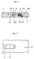
- Fig. 3 shows the section through the tube wall opening 4 according to FIG. 2.
- the locking piece 5 is embedded, so that the locking element 3 can no longer come out of its seat in the receiving chamber by vibration or rotation of the tubes.
Landscapes
- Engineering & Computer Science (AREA)
- General Engineering & Computer Science (AREA)
- Health & Medical Sciences (AREA)
- Life Sciences & Earth Sciences (AREA)
- Hydrology & Water Resources (AREA)
- Public Health (AREA)
- Water Supply & Treatment (AREA)
- Mechanical Engineering (AREA)
- Quick-Acting Or Multi-Walled Pipe Joints (AREA)
- Mechanical Coupling Of Light Guides (AREA)
- Non-Disconnectible Joints And Screw-Threaded Joints (AREA)
- Joints With Sleeves (AREA)
Applications Claiming Priority (2)
| Application Number | Priority Date | Filing Date | Title |
|---|---|---|---|
| DE29608706U DE29608706U1 (de) | 1996-05-14 | 1996-05-14 | Rohrverbindung |
| DE29608706U | 1996-05-14 |
Publications (3)
| Publication Number | Publication Date |
|---|---|
| EP0807782A2 true EP0807782A2 (fr) | 1997-11-19 |
| EP0807782A3 EP0807782A3 (fr) | 1998-04-15 |
| EP0807782B1 EP0807782B1 (fr) | 2001-05-23 |
Family
ID=8023949
Family Applications (1)
| Application Number | Title | Priority Date | Filing Date |
|---|---|---|---|
| EP97106036A Expired - Lifetime EP0807782B1 (fr) | 1996-05-14 | 1997-04-12 | Raccord de tuyaux |
Country Status (3)
| Country | Link |
|---|---|
| EP (1) | EP0807782B1 (fr) |
| DE (2) | DE29608706U1 (fr) |
| DK (1) | DK0807782T3 (fr) |
Cited By (1)
| Publication number | Priority date | Publication date | Assignee | Title |
|---|---|---|---|---|
| US20160177785A1 (en) * | 2014-12-22 | 2016-06-23 | Rolls-Royce Plc | Joint assembly and a method of using the same |
Families Citing this family (2)
| Publication number | Priority date | Publication date | Assignee | Title |
|---|---|---|---|---|
| US9441651B2 (en) | 2012-12-10 | 2016-09-13 | Rolls-Royce Plc | Joint assembly and method of using the same |
| GB201915814D0 (en) * | 2019-10-31 | 2019-12-18 | Rolls Royce Plc | Joint assembly |
Family Cites Families (9)
| Publication number | Priority date | Publication date | Assignee | Title |
|---|---|---|---|---|
| GB1066936A (en) * | 1965-04-09 | 1967-04-26 | Btr Industries Ltd | A releasable pipe coupling |
| DE2106106A1 (de) * | 1971-02-09 | 1972-08-24 | Eternit Ag | Rohrverbindung |
| US4293148A (en) * | 1979-02-22 | 1981-10-06 | Fmc Corporation | Pile connector |
| DE3822276A1 (de) * | 1987-07-24 | 1989-02-02 | Bohrtec Gmbh & Co Kg Fuer Bohr | Vorpressrohr |
| DE8805742U1 (de) * | 1988-04-30 | 1988-06-16 | REHAU AG + Co, 8673 Rehau | Rohrverbindung |
| DE3814913A1 (de) * | 1988-05-03 | 1989-11-16 | Rehau Ag & Co | Rohrverbindung |
| DE3844045A1 (de) * | 1988-12-28 | 1990-07-05 | Rehau Ag & Co | Rohrverbindung |
| JPH0672679B2 (ja) * | 1990-01-17 | 1994-09-14 | 八郎 井上 | 界面継手 |
| DE4205278C1 (fr) * | 1992-02-21 | 1993-05-06 | Bode Gmbh, 2000 Hamburg, De |
-
1996
- 1996-05-14 DE DE29608706U patent/DE29608706U1/de not_active Expired - Lifetime
-
1997
- 1997-04-12 EP EP97106036A patent/EP0807782B1/fr not_active Expired - Lifetime
- 1997-04-12 DE DE59703580T patent/DE59703580D1/de not_active Expired - Fee Related
- 1997-04-12 DK DK97106036T patent/DK0807782T3/da active
Cited By (2)
| Publication number | Priority date | Publication date | Assignee | Title |
|---|---|---|---|---|
| US20160177785A1 (en) * | 2014-12-22 | 2016-06-23 | Rolls-Royce Plc | Joint assembly and a method of using the same |
| US10100961B2 (en) * | 2014-12-22 | 2018-10-16 | Rolls-Royce Plc | Joint assembly and a method of using the same |
Also Published As
| Publication number | Publication date |
|---|---|
| DE59703580D1 (de) | 2001-06-28 |
| EP0807782A3 (fr) | 1998-04-15 |
| EP0807782B1 (fr) | 2001-05-23 |
| DK0807782T3 (da) | 2001-08-06 |
| DE29608706U1 (de) | 1996-08-08 |
Similar Documents
| Publication | Publication Date | Title |
|---|---|---|
| EP0932789B1 (fr) | Raccord par emboitement pour conduites rigides | |
| EP2933542B1 (fr) | Dispositif de raccordement pour tuyaux ondulés | |
| EP2246607A1 (fr) | Raccord pour tuyaux d'eau | |
| EP3428498B1 (fr) | Tube, en particulier tube en plastique pour conduites d'évacuation d'eaux usées | |
| DE4030323A1 (de) | Rohrpresskupplung | |
| EP2044359A1 (fr) | Manchon et combinaison de manchon avec un outil de moulage par compression | |
| DE2118781A1 (de) | Rohrdichtung | |
| EP1288554A1 (fr) | Dispositif de connexion pour un tube | |
| DE4117932C2 (fr) | ||
| DE19929010C1 (de) | Kunststofformteil sowie Verbindungsvorrichtung mit diesem | |
| EP0807782A2 (fr) | Raccord de tuyaux | |
| DE3104518A1 (de) | Anschlussarmatur | |
| AT294503B (de) | Rohrverbindung | |
| DE19728137C1 (de) | Steckverbindung für Rohrleitungen | |
| DE102007060490B4 (de) | Schlauchanschluss | |
| WO2000060267A1 (fr) | Dispositif pour l'assemblage de tubes | |
| EP2476939A2 (fr) | Raccord pour le raccordement d'une extrémité de tuyau | |
| EP0863357A2 (fr) | Raccord de tuyaux | |
| AT265770B (de) | Selbstdichtende Rohrkupplung | |
| EP3112736A1 (fr) | Blocage en traction | |
| DE3122846C2 (de) | Muffe | |
| DE4404520A1 (de) | Schnellkupplung für Rohrleitungen, insbesondere für Luftleitungen einer Heizungs- und Belüftungs- bzw. einer Klimaanlage eines Kraftfahrzeugs | |
| AT515540B1 (de) | Anschlussteil für eine Rohrleitung | |
| DE9319397U1 (de) | Kupplung für Mörtelschläuche | |
| CH454553A (de) | Selbstdichtende Rohrkupplung |
Legal Events
| Date | Code | Title | Description |
|---|---|---|---|
| PUAI | Public reference made under article 153(3) epc to a published international application that has entered the european phase |
Free format text: ORIGINAL CODE: 0009012 |
|
| AK | Designated contracting states |
Kind code of ref document: A2 Designated state(s): DE DK FR SE |
|
| PUAL | Search report despatched |
Free format text: ORIGINAL CODE: 0009013 |
|
| AK | Designated contracting states |
Kind code of ref document: A3 Designated state(s): DE DK FR SE |
|
| 17P | Request for examination filed |
Effective date: 19980430 |
|
| 17Q | First examination report despatched |
Effective date: 19981106 |
|
| GRAG | Despatch of communication of intention to grant |
Free format text: ORIGINAL CODE: EPIDOS AGRA |
|
| GRAG | Despatch of communication of intention to grant |
Free format text: ORIGINAL CODE: EPIDOS AGRA |
|
| GRAH | Despatch of communication of intention to grant a patent |
Free format text: ORIGINAL CODE: EPIDOS IGRA |
|
| GRAH | Despatch of communication of intention to grant a patent |
Free format text: ORIGINAL CODE: EPIDOS IGRA |
|
| GRAA | (expected) grant |
Free format text: ORIGINAL CODE: 0009210 |
|
| AK | Designated contracting states |
Kind code of ref document: B1 Designated state(s): DE DK FR SE |
|
| REF | Corresponds to: |
Ref document number: 59703580 Country of ref document: DE Date of ref document: 20010628 |
|
| REG | Reference to a national code |
Ref country code: DK Ref legal event code: T3 |
|
| ET | Fr: translation filed | ||
| PLBE | No opposition filed within time limit |
Free format text: ORIGINAL CODE: 0009261 |
|
| STAA | Information on the status of an ep patent application or granted ep patent |
Free format text: STATUS: NO OPPOSITION FILED WITHIN TIME LIMIT |
|
| PGFP | Annual fee paid to national office [announced via postgrant information from national office to epo] |
Ref country code: SE Payment date: 20020514 Year of fee payment: 6 |
|
| PGFP | Annual fee paid to national office [announced via postgrant information from national office to epo] |
Ref country code: DK Payment date: 20020515 Year of fee payment: 6 |
|
| 26N | No opposition filed | ||
| PGFP | Annual fee paid to national office [announced via postgrant information from national office to epo] |
Ref country code: FR Payment date: 20030313 Year of fee payment: 7 |
|
| PGFP | Annual fee paid to national office [announced via postgrant information from national office to epo] |
Ref country code: DE Payment date: 20030318 Year of fee payment: 7 |
|
| PG25 | Lapsed in a contracting state [announced via postgrant information from national office to epo] |
Ref country code: SE Free format text: LAPSE BECAUSE OF NON-PAYMENT OF DUE FEES Effective date: 20030413 |
|
| PG25 | Lapsed in a contracting state [announced via postgrant information from national office to epo] |
Ref country code: DK Free format text: LAPSE BECAUSE OF NON-PAYMENT OF DUE FEES Effective date: 20030430 |
|
| EUG | Se: european patent has lapsed | ||
| REG | Reference to a national code |
Ref country code: DK Ref legal event code: EBP |
|
| PG25 | Lapsed in a contracting state [announced via postgrant information from national office to epo] |
Ref country code: DE Free format text: LAPSE BECAUSE OF NON-PAYMENT OF DUE FEES Effective date: 20041103 |
|
| PG25 | Lapsed in a contracting state [announced via postgrant information from national office to epo] |
Ref country code: FR Free format text: LAPSE BECAUSE OF NON-PAYMENT OF DUE FEES Effective date: 20041231 |
|
| REG | Reference to a national code |
Ref country code: FR Ref legal event code: ST |