EP0807724B1 - Security device for skylight openings - Google Patents
Security device for skylight openings Download PDFInfo
- Publication number
- EP0807724B1 EP0807724B1 EP96107672A EP96107672A EP0807724B1 EP 0807724 B1 EP0807724 B1 EP 0807724B1 EP 96107672 A EP96107672 A EP 96107672A EP 96107672 A EP96107672 A EP 96107672A EP 0807724 B1 EP0807724 B1 EP 0807724B1
- Authority
- EP
- European Patent Office
- Prior art keywords
- profiles
- tubes
- rods
- security device
- profile
- Prior art date
- Legal status (The legal status is an assumption and is not a legal conclusion. Google has not performed a legal analysis and makes no representation as to the accuracy of the status listed.)
- Expired - Lifetime
Links
Images
Classifications
-
- E—FIXED CONSTRUCTIONS
- E04—BUILDING
- E04D—ROOF COVERINGS; SKY-LIGHTS; GUTTERS; ROOF-WORKING TOOLS
- E04D13/00—Special arrangements or devices in connection with roof coverings; Protection against birds; Roof drainage; Sky-lights
- E04D13/03—Sky-lights; Domes; Ventilating sky-lights
- E04D13/0335—Skylight guards, security devices protecting skylights or preventing objects or persons from falling through skylight openings
-
- E—FIXED CONSTRUCTIONS
- E06—DOORS, WINDOWS, SHUTTERS, OR ROLLER BLINDS IN GENERAL; LADDERS
- E06B—FIXED OR MOVABLE CLOSURES FOR OPENINGS IN BUILDINGS, VEHICLES, FENCES OR LIKE ENCLOSURES IN GENERAL, e.g. DOORS, WINDOWS, BLINDS, GATES
- E06B9/00—Screening or protective devices for wall or similar openings, with or without operating or securing mechanisms; Closures of similar construction
- E06B9/01—Grilles fixed to walls, doors, or windows; Grilles moving with doors or windows; Walls formed as grilles, e.g. claustra
Definitions
- the invention relates to a safety device for a Roof opening, which according to the genus by the generic term of claim 1 is described.
- Roof openings must be secured against falling through. Such safety devices prescribed by standards on the one hand to the fall of objects To prevent roof breaks and fall injuries from on the Avoid people working on the roof. On the other hand, should be open Roof openings are closed in such a way that burglar resistance is guaranteed.
- German utility models G 91 05 567 and G 91 10 266 are kits for safety devices for roof openings known in which the opening cross-section of the roof opening secured against falling through with a plank frame and a grid becomes.
- the plank frame is under an upstand arranged and laid from the outside around the roof opening.
- a disadvantage of these so-called "under-construction solutions” for securing a roof opening is, however, the first caused by the additional installation of the plank frame constructional enlargement. This can also give the visual impression Suffer.
- a safety device is from the German utility model G 91 02 620 known, in which in a separate Fasteners are provided on the inside of the roof frame to which a fall protection can be attached.
- This type of securing roof openings also brings Disadvantage of tightness problems compared to the rest of the roof skin with yourself.
- this type of security device offers only a very limited protection against burglary since the Blocking of the roof opening from the outside relatively is easy to disassemble.
- the features of the preamble of claim 1 shows.
- the bars are placed between two base profiles using two cover profiles attached.
- the base profiles have a U-shape with one facing inwards Grid on both legs.
- the cover profiles also have a U-shape, but with an outward-facing grid on the legs.
- the cover profiles are in the Base profiles hammered in to engage.
- German utility model 92 10 122 U1 Another disadvantage of the grating device shown in German utility model 92 10 122 U1 is their very low adaptability to different Angular positions of the boundary walls of the roof opening.
- the inside or outside profiling of the different profile parts causes a rigid locking, due to the rigidity of the material (hammering in) hardly any room for installation Breakthrough limits that are not parallel to each other.
- the configuration according to the invention has an advantageous effect in that the hooking and locking process when attaching the cover profiles to the support profiles easily can be done in very different angular positions.
- the scope of the Roof penetration protection according to the invention is therefore not on such roof openings limited with parallel walls as parallel as possible.
- the support profiles are the safety device according to the invention flat longitudinal profiles, while the cover profiles are essentially of the same length are. Both profiles show both in the upper and in lower hooks and latching devices on.
- the design of the upper hanging device as a longitudinal groove and hook bar creates a weight pressure distribution on the whole Profile length. So that even at relatively low Dimensions and material thicknesses of the profiles are relatively large loads be included.
- the mechanical fastenings are completely covered by the cover strip after snapping into place.
- the Burglar resistance is given because the mechanical fastenings, for example from screws, rivets or all similar fasteners may not exist are more accessible from the outside. If special tightness requirements are of course also possible the support bar without damaging the roof opening add, e.g. by gluing or similar acting Joining measures.
- the safety bars or tubes or the ends of the steel mesh mat must be behind their mounting holes in the cover profile secured against being pulled out.
- securing means preferably clamping rings, Nuts, notched rivets or grooved pins and especially at the steel mesh mat by bending the rod ends and the Use of anti-slip devices.
- the rods or tubes can already be factory-made with the aforementioned securing devices be attached to the cover profile. After locking the cover profile the securing means are located with the rods on the support profile in the interior between the profiles and are from no longer accessible outside. In this regard, too Burglar security guaranteed.
- At least one across the securing rods or tubes Support web through which the rods or tubes pass.
- the support web is advantageously so on the rods or Tubes locked so that it can no longer be moved sideways.
- fastening is a simple variant of the support web on two rods or tubes, namely preferably on the two outermost, although the free one Rotation of these rods or tubes is no longer possible however, a secure hold of the support web is guaranteed.
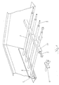
- the safety device consists of an angled area of the curb attached support profile 1, in the shown in Condition a cover profile 6 is hooked and locked.
- the Cover profile 6 takes safety tubes 2 at their ends.
- the Safety tubes 2 run across the roof opening and go through at a distance from the support or support profile 1, 6 a support web 11 running over them.
- This Support web 11 increases the stability on the one hand as a load distributor the arrangement and on the other hand prevents bending apart of tubes 2.
- the tubes 2 are fixed except for those for locking connected to the support bar, freely rotatable in their recordings stored in the cover profile 6 and in the support web 11, as by the Arrows is indicated on the front tube shown.
- roller bars 5 record, which, as previously described, the burglar resistance increase because they saw through the pipes 2 and Prevent support web 11.
- the roller bar 5 is located in the support web 11 freely rotatable on the tubes 2. Also in the pipes 2 Roll rod 5 inserted freely rotatable.
- the upper hanging device consists of the one open at the top Longitudinal groove 3 on the support profile and the one protruding downwards Hook bar 7 on the cover profile.
- the attachment takes place on this Just put in the hook bar 7 of the Cover profile 6 in the longitudinal groove 3 from above.
- the locking bar 8 is located with their upper undercut behind the latching extension 9 of the Carrying profile 1 and is thus secured against being pulled out. Adequate tension is ensured by the elasticity of the respective components ensured.
- the dead weight of the safety device is in this state by the upper hanging device, i.e. the hook bar 7 and the longitudinal groove 3 held.
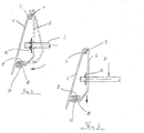
- FIG. 3 shows the arrangement from FIG. 2 in the state in a load on the pipe structure of the safety device works. Such a load is particularly caused by a heavy object or person exercised by the Safety device against falling through the roof opening is prevented.
Landscapes
- Engineering & Computer Science (AREA)
- Structural Engineering (AREA)
- Architecture (AREA)
- Civil Engineering (AREA)
- Emergency Lowering Means (AREA)
- Roof Covering Using Slabs Or Stiff Sheets (AREA)
- Tents Or Canopies (AREA)
- Buildings Adapted To Withstand Abnormal External Influences (AREA)
Abstract
Description
Die Erfindung betrifft eine Sicherungsvorrichtung für einen
Dachdurchbruch, welcher der Gattung nach durch den Oberbegriff
des Patentanspruchs 1 beschrieben wird.The invention relates to a safety device for a
Roof opening, which according to the genus by the generic term
of
Dachdurchbrüche müssen gegen Durchsturz gesichert werden. Solche durch Normen vorgeschriebenen Sicherungsvorrichtungen dienen einerseits dazu, den Sturz von Gegenständen durch Dachdurchbrüche zu verhindern und Sturzverletzungen von auf dem Dach tätigen Personen zu vermeiden. Andererseits sollten offene Dachdurchbrüche so verschlossen werden, daß die Einbruchssicherheit gewährleistet ist.Roof openings must be secured against falling through. Such safety devices prescribed by standards on the one hand to the fall of objects To prevent roof breaks and fall injuries from on the Avoid people working on the roof. On the other hand, should be open Roof openings are closed in such a way that burglar resistance is guaranteed.
Aus den deutschen Gebrauchsmustern G 91 05 567 und G 91 10 266 sind Bausätze für Sicherungsvorrichtungen für Dachdurchbrüche bekannt, bei denen der Öffnungsquerschnitt des Dachdurchbruches mit einem Bohlenrahmen und einem Gitter gegen Durchsturz gesichert wird. Der Bohlenrahmen ist dabei unter einem Aufsetzkranz angeordnet und von außen um den Dachdurchbruch verlegt. Nachteilig bei diesen sogenannten "Unterbaulösungen" zur Sicherung eines Dachdurchbruches ist jedoch zunächst einmal die durch den zusätzlichen Einbau des Bohlenrahmens verursachte bauliche Vergrößerung. Hierdurch kann auch der visuelle Eindruck leiden. Desweiteren bringt ein hinzukommendes Einbau-element zusätzliche Schwachpunkte mit sich. So treten z.B. Dichtheitsprobleme gegenüber der restlichen Dachhaut auf, welche zusätzliche Arbeiten zur Eindichtung erforderlich machen.From German utility models G 91 05 567 and G 91 10 266 are kits for safety devices for roof openings known in which the opening cross-section of the roof opening secured against falling through with a plank frame and a grid becomes. The plank frame is under an upstand arranged and laid from the outside around the roof opening. A disadvantage of these so-called "under-construction solutions" for securing a roof opening is, however, the first caused by the additional installation of the plank frame constructional enlargement. This can also give the visual impression Suffer. Furthermore, there is an additional installation element additional weaknesses. For example, Leakage problems with the rest of the roof skin, which make additional sealing work necessary.
Aus dem deutschen Gebrauchsmuster G 91 02 620 ist eine Sicherungsvorrichtung bekannt, bei welcher in einem gesonderten Dachrahmen innenseitig Befestigungsmittel vorgesehen sind, an denen eine Durchsturzsicherung angebracht werden kann. Diese Art der Sicherung von Dachdurchbrüchen bringt ebenfalls den Nachteil von Dichtheitsproblemen gegenüber der restlichen Dachhaut mit sich. Ferner bietet diese Art von Sicherheitsvorrichtungen nur einen sehr eingeschränkten Einbruchsschutz, da die Versperrung des Dachdurchbruchs von der Außenseite her relativ einfach demontierbar ist.A safety device is from the German utility model G 91 02 620 known, in which in a separate Fasteners are provided on the inside of the roof frame to which a fall protection can be attached. This The type of securing roof openings also brings Disadvantage of tightness problems compared to the rest of the roof skin with yourself. Furthermore, this type of security device offers only a very limited protection against burglary since the Blocking of the roof opening from the outside relatively is easy to disassemble.
Im allgemeinen haben Holzbohlenrahmen schon aufgrund ihres Materials nachteilige Brandeigenschaften. Ein weiterer Nachteil, der bekannten Durchsturzvorrichtungen anhaftet, betrifft die Tatsache, daß sie als Bausätze regelmäßig nur für Neuaufbauten vorgesehen sind. Da es oftmals notwendig ist, in bereits fertigen Dächern befindliche Dachdurchbrüche gegen Durchsturz und Einbruch zu sichern, besteht im Stand die Technik dahingehend ein Defizit, daß nachrüstbare Sicherungsvorrichtungen für Dachdurchbrüche, die sowohl durchsturz- als auch einbruchssicher sind und auf die jeweils vorzufindende Maßsituation angepaßt werden können, noch nicht vorgeschlagen oder angeboten werden. In general, wooden planks have frames because of their material adverse fire properties. Another disadvantage, of the known fall-through devices, affects the The fact that they are usually only as kits for new buildings are provided. Because it is often necessary to manufacture in already Roof breakthroughs against collapse and To secure burglary, the technology exists in this regard a deficit that retrofittable safety devices for roof openings, which are both fall-proof and burglar-proof are and adapted to the respective dimensional situation to be found cannot be proposed or offered yet.
In der deutschen Gebrauchsmusterschrift Nr. 92 10 122 wird ein Spezialgitter für
Bauwerksöffnungen beschrieben, das die Merkmale des Oberbegriffs des Patentanspruchs 1
zeigt. Die Gitterstäbe werden zwischen zwei Basisprofilen mittels zweier Deckprofile
befestigt. Hierbei haben die Basisprofile eine U-Form mit einer nach innen zeigenden
Rasterung an beiden Schenkeln. Auch die Deckprofile zeigen eine U-Form, allerdings mit
einer nach außen zeigenden Rasterung an den Schenkeln. Die Deckprofile werden in die
Basisprofile eingehämmert, um eine Verrastung durchzuführen.In the German utility model no. 92 10 122 a special grill for
Building openings described, the features of the preamble of
Diese Befestigungart für Gitterstäbe weist nun bei horizontaler Einbaulage einige gravierende Nachteile auf. Wie der Gebrauchsmusterschrift Nr. 92 10 122 U1 insgesamt zu entnehmen ist, ist eine solche Befestigung für Gitterstäbe wohl am ehesten für Fenstersicherungen geeignet. Wendet man dieses Gitter nämlich horizontal an und zieht eine stoßartige Belastung der Gitterstäbe von oben in Betracht, wird deutlich, daß die Last nur von den jeweils unteren U-Schenkeln der Basisprofile sowie der Deckprofile aufgenommen werden kann. Eine Lastverteilung auch auf die oberen Schenkel dieser Profile ist nicht möglich. Um die Belastungsfähigkeit zu verbessern müßten die Profile relativ dickwandig her-gestellt werden, was aber die Funktion des Verrastungsprinzips nicht zuläßt, da hier eine Flexibilität der Schenkel erforderlich ist.This type of fastening for bars now has some serious problems when installed horizontally Disadvantages. As can be seen from utility model no. 92 10 122 U1 as a whole, is such a fastening for bars probably best suited for window locks. If you apply this grid horizontally and pull a shock-like load on the Considering bars from above, it becomes clear that the load only from the lower U-legs the base profiles and the cover profiles can be added. A Load distribution on the upper legs of these profiles is also not possible. To the To improve the load capacity, the profiles would have to be made relatively thick-walled, but what the function of the locking principle does not allow, since here a flexibility of Thigh is required.
Eine weitere Einschränkung des Systems wird dabei offenkundig. Es kann horizontal nicht bei größeren Öffnungsquerschnitten eingesetzt werden, da die relativ hohe Eigenlast der schweren Gitterstäbe mit Rollkernen nicht getragen werden kann. Ein Bruch oder Auslenken nur eines der unteren Schenkel, des Basisprofils der des Abdeckprofils hat im vorbeschriebenen Lastfall sofort ein Zusammenbrechen der gesamten Halterung zur Folge.A further limitation of the system becomes apparent. It cannot be horizontal larger opening cross-sections can be used because the relatively high dead weight of the heavy bars with roller cores can not be carried. A break or deflection only one of the lower legs, the base profile of the cover profile has the above In the event of a load, the entire bracket collapses immediately.
Ein weiterer Nachteil der im deutschen Gebrauchsmuster 92 10 122 U1 gezeigten Gittervorrichtung besteht in ihrer sehr geringen Anpassungsfähigkeit an verschiedene Winkellagen der Begrenzungswände des Dachdurchbruchs. Die Innen- bzw. Außenprofilierung der verschiedenen Profilteile bewirkt ein starres Verrasten, das wegen der Steifigkeit des Materials (Einschlagen mit einem Hammer) kaum Spielraum für den Einbau bei Durchbruchsbegrenzungen, welche nicht parallel zueinander liegen, gibt. Another disadvantage of the grating device shown in German utility model 92 10 122 U1 is their very low adaptability to different Angular positions of the boundary walls of the roof opening. The inside or outside profiling of the different profile parts causes a rigid locking, due to the rigidity of the material (hammering in) hardly any room for installation Breakthrough limits that are not parallel to each other.
Die DE-91 04 661 U1 beschreibt wiederum ein Gitter für ein Fenster. Die Profile der Befestigungseinrichtung für das Gitter sind ähnlich wie diejenigen aus dem oben diskutierten Gebrauchsmuster Nr. 92 10 122 U1 ausgestaltet, jedoch weist das Abdeckprofil eine doppelwandige, mit Rasterungen versehene Ausgestaltung auf. Hier bestehen wieder die schon oben angesprochenen Bedenken. Ansonsten ist auch dieses Gitter lediglich für den Einbau in ein Fenster gedacht; besonders vorteilhafte Ausgestaltungen als Dachdurchbruchsicherung sind nicht erkennbar.DE-91 04 661 U1 again describes a grille for a window. The profiles of the Fastening devices for the grille are similar to those from the one discussed above Utility model No. 92 10 122 U1 designed, but the cover profile has one double-walled design with grids. Here again there are concerns raised above. Otherwise, this grid is only for the Installation in a window thought; particularly advantageous configurations as Roof penetration protection is not recognizable.
Es ist die Aufgabe der vorliegenden Erfindung, eine speziell für Dachdurchbrüche in im wesentlichen horizontaler Anordnung geeignete Sicherungsvorrichtung vorzuschlagen, die die obigen Nachteile nicht mehr aufweist. Insbesondere soll eine solche Sicherungsvorrichtung bereitgestellt werden, die eine optimierte Lastverteilung bei Stößen, sowie eine gute Winkelanpassungsfähigkeit bietet.It is the object of the present invention, a specially for roof openings in essential horizontal arrangement to propose suitable safety device that the no longer has the above disadvantages. In particular, such a safety device be provided, the optimized load distribution in the event of impacts, as well as a good one Offers angular adaptability.
Die obige Aufgabe wird erfindungsgemäß dadurch gelöst, daß die Abdeckprofile an den Trageprofilen durch Einhängen der Abdeckprofile am oberen Längsbereich und durch Verrasten an deren unteren Längsbereich zu befestigen sind. Durch dieses Einhängen der Abdeckprofile an dem oberen Längsbereich und das Verrasten am unteren Längsrand entstehen an beiden Längsrändern der Profile Lagerungsstellen, die einen Stoß von oben aufnehmen können. Die Stoßkraft, beispielsweise beim Aufprall auf die Gitterstäbe, wird deshalb auf zwei Lagerungen verteilt und damit je Lagerung (Einhängbereich/Rastbereich) etwa um die Hälfte verringert: Dies eröffnet die Möglichkeit, die Profile mit einem geringeren Materialaufwand herzustellen und trotzdem eine durchbruchsichere Vorrichtung zur Verfügung zu stellen.The above object is achieved in that the cover profiles to the Support profiles by hanging the cover profiles on the upper longitudinal area and through Snap to their lower longitudinal area to be fastened. By hanging the Cover profiles on the upper longitudinal area and locking on the lower longitudinal edge Bearing points arise on both longitudinal edges of the profiles, which impact from above be able to record. The impact force, for example upon impact with the bars, is increased therefore divided into two positions and therefore each position (hanging area / rest area) reduced by about half: This opens up the possibility of reducing the profiles Manufacture of materials and still a breakthrough-proof device for To make available.
Weiterhin wirkt sich die erfindungsgemäße Ausgestaltung dahingehend vorteilhaft aus, daß der Einhäng- und Rastvorgang beim Befestigen der Abdeckprofile an den Trageprofile leicht in sehr verschiedenen Winkelstellungen erfolgen kann. Der Anwendungsbereich der erfindungsgemäßen Dachdurchbruchsicherung ist deshalb nicht auf solche Dachdurchbrüche mit möglichst parallelen Begrenzungswänden beschränkt. Furthermore, the configuration according to the invention has an advantageous effect in that the hooking and locking process when attaching the cover profiles to the support profiles easily can be done in very different angular positions. The scope of the Roof penetration protection according to the invention is therefore not on such roof openings limited with parallel walls as parallel as possible.
Gemäß einer bevorzugten Ausgestaltung sind die Trageprofile der erfindungsgemäßen Sicherungsvorrichtung flache Längsprofile, während die Abdeckprofile im wesentlichen gleich lange Konturprofile sind. Beide Profile weisen sowohl im oberen als auch im unteren Längswandbereich verlaufende Einhänge- bzw. Rasteinrichtungen auf.According to a preferred embodiment, the support profiles are the safety device according to the invention flat longitudinal profiles, while the cover profiles are essentially of the same length are. Both profiles show both in the upper and in lower hooks and latching devices on.
Der Vorteil solcher Profile besteht zunächst in ihrer relativ einfachen und konstengünstigen Herstellbarkeit und weiterhin darin, daß durch die Einhänge- und Rasteinrichtungen eine leichte Montierbarkeit gewährleistet ist. Ferner können solche Längsprofile einfach werkseitig, aber auch beim Einbau auf vorgegebene Längen angepaßt und an im wesentlichen allen inneren Seitenwänden von Dachdurchbrüchen befestigt werden. Die Befestigung durch Einhängen der Abdeckprofile am oberen Längsrandbereich der Trageprofile und Verrasten an deren unterem Längsrand schafft einen großen Anwendungsspielraum, was die Winkelsituation an der Innenseitenwand des Dachdurchbruchs betrifft. Solche inneren Seitenwände verlaufen nicht regelmäßig senkrecht zur Dachoberfläche. Vielmehr sind oftmals variierende Winkelsituationen gegeben, die insbesondere bei an Durchbrüchen angebrachten Aufsetzkränzen bestehen können. Es muß deshalb das Problem gelöst werden, der nachrüstbaren Sicherungsvorrichtung beim Winkel zwischen der durch die Sicherungsrohre oder -stäbe bzw. die Stahlgewebematte vorgegebenen Ebene und der Trageprofil-Anbringungsebene einen genügenden Spielraum einzuräumen. Das Einhängen der Abdeckprofile am oberen Längsrand der Tragprofile und das Verrasten dieser beiden Profile am unteren Längsrand schafft einen sehr großen Spielraum für variierende Winkelsituationen. Hierdurch wird die Nachrüstbarkeit der erfindungsgemäßen Sicherungsvorrichtung weitgehend unabhängig von der anzutreffenden Bausituation.The advantage of such profiles is their relative simple and inexpensive to manufacture and continue in that a by the hanging and locking devices easy assembly is guaranteed. Furthermore, such Longitudinal profiles simply at the factory, but also when installing to the specified ones Adjusted lengths and on essentially all inner Side walls of roof openings are attached. The attachment by hanging the cover profiles on the upper longitudinal edge area of the support profiles and locking on their lower longitudinal edge creates a wide range of applications, whatever the angular situation on the inside wall of the roof opening. Such inner side walls are not regularly vertical to the roof surface. Rather, there are often varying angular situations given, especially when attached to breakthroughs Curbs can exist. It must therefore Problem can be solved, the retrofittable safety device at the angle between that through the security tubes or rods or the steel mesh mat predetermined level and the support profile attachment level to give sufficient scope. Hooking the cover profiles onto the upper longitudinal edge of the support profiles and locking these two profiles at the bottom Longitudinal edge creates a very large scope for varying Angular situations. This retrofits the invention Securing device largely independent of the construction situation encountered.
Eine Möglichkeit, die vorher beschriebenen Einhänge- bzw. Rasteinrichtungen auszugestalten, besteht darin, die am oberen Längsrand verlaufende Einhängeeinrichtung am Trageprofil auf einer nach oben offenen Längsrille und am Abdeckprofil aus einer Hakenleiste auszubilden, während die am unteren Längsrand verlaufende Rasteinrichtung am Trageprofil aus einer Rastnut mit oberen und unteren Rastfortsätzen und am Abdeckprofil aus einer mit den Rastfortsätzen in Eingriff bringbaren Rastleiste besteht.One possibility, the hanging or locking devices described above to design is the one at the top Longitudinal hanging device on the support profile an upward open longitudinal groove and on the cover profile from one Train hook ledge while at the bottom longitudinal edge running locking device on the support profile from a locking groove with upper and lower snap extensions and on the cover profile a locking bar that can be brought into engagement with the locking extensions consists.
Die Ausbildung der oberen Einhängeeinrichtung als Längsrille und Hakenleiste schafft eine Gewichtsdruckteilung auf die gesamte Länge des Profils. Damit können auch bei relativ geringen Abmessungen und Materialstärken der Profile relativ große Lasten aufgenommen werden. Die mechanischen Befestigungen sind nach dem Einrasten durch die Abdeckleiste völlig abgedeckt. Die Einbruchssicherheit ist gegeben, weil die mechanischen Befestigungen, die beispielsweise aus Schrauben, Nieten oder allen ähnlich wirkenden Befestigungsmitteln bestehen können, nicht mehr von außen zugänglich sind. Wenn besondere Dichtigkeitsvoraussetzungen zu erfüllen sind, besteht natürlich auch die Möglichkeit, die Tragleiste ohne eine Beschädigung des Dachdurchbruchs anzufügen, z.B. durch Kleben oder ähnliche wirkende Fügemaßnahmen.The design of the upper hanging device as a longitudinal groove and hook bar creates a weight pressure distribution on the whole Profile length. So that even at relatively low Dimensions and material thicknesses of the profiles are relatively large loads be included. The mechanical fastenings are completely covered by the cover strip after snapping into place. The Burglar resistance is given because the mechanical fastenings, for example from screws, rivets or all similar fasteners may not exist are more accessible from the outside. If special tightness requirements are of course also possible the support bar without damaging the roof opening add, e.g. by gluing or similar acting Joining measures.
Besonders vorteilhaft wirkt sich die oben angesprochene erfindungsgemäße Ausgestaltung der Rasteinrichtungen am unteren Längsrand der Profile aus. Die Rasteinrichtung besteht am Trageprofil aus einer Rastnut mit oberen und unteren Rastfortsätzen. Wenn die Sicherungsvorrichtung unbelastet in die obere Einhängeeinrichtung eingehängt und am unteren Längsrand verrastet wird, kommt der obere Rastfortsatz am Trageprofil mit einer oberen Hinterschneidung der Rastleiste in Eingriff und sichert so unlösbar das Abdeckprofil am Trageprofil. Bei einer Gewichtsbelastung, wenn beispielsweise eine Person oder ein schwerer Gegenstand auf die Sicherungsrohre oder -stäbe bzw. die Stahlgewebematte fällt, erfährt das Abdeckprofil und insbesondere dessen unterer Abschnitt mit der Rastleiste ein Bewegung nach unten, wobei sie mit einer unteren Hinterschneidung mit dem unteren Rastfortsatz des Abdeckprofils in Eingriff kommt. Dadurch wird ein Ausrutschen der Rastverbindung auch bei einer Gewichtsbelastung verhindert. Weiterhin trägt das Profilleistenpaar nunmehr das Gewicht sowohl an der oberen Einhängeeinrichtung als auch an der unteren Rastvorrichtung. Da dies auch bei der unteren Rasteinrichtung über die gesamte Länge der Profile geschieht, können relativ große Lasten aufgenommen werden. The above-mentioned invention has a particularly advantageous effect Design of the locking devices at the bottom Long edge of the profiles. The locking device is on the support profile from a notch with upper and lower notches. If the safety device is unloaded in the upper Hook-in device hooked in and locked at the lower longitudinal edge the upper latching extension on the support profile comes with a upper undercut of the locking bar engages and secures so insoluble the cover profile on the support profile. At a Weight load if for example a person or a heavy object on the safety tubes or rods or the steel mesh mat falls, experiences the cover profile and in particular whose lower section with the locking bar a movement down with a lower undercut engages with the lower catch extension of the cover profile is coming. This will also cause the locking connection to slip a weight load prevented. The pair of profile strips also carries now the weight of both the upper hanging device as well as on the lower locking device. As this also with the lower locking device over the entire length of the Profiles happening can accommodate relatively large loads become.
Vorzugsweise ist das Abdeckprofil ein im Mittelbereich abgewinkeltes Konturprofil. Durch diese Ausgestaltung des Abdeckprofils wird zwischen diesem und dem Trageprofil im montierten Zustand genügend Raum für die Unterbringung der mechanischen Befestigungen des Trageprofils und der in diesen Raum hineinragenden Sicherungsrohre oder -stäbe bzw. der Stabenden der Stahlgewebematte und ihrer Halterungen geschaffen.The cover profile is preferably angled in the central region Contour profile. This configuration of the cover profile is mounted between this and the support profile in the Condition enough space for housing the mechanical Fastening the support profile and those protruding into this room Safety tubes or rods or the rod ends of the Steel mesh mat and its brackets created.
Die Aufnahme für die Sicherungsstäbe oder -rohre bzw. der Stahlgewebematte im Abdeckprofil sind gemäß einer bevorzugten Ausgestaltung der Sicherungsvorrichtung langlochartig ausgebildet. Die Langlöcher erstrecken sich hierbei senkrecht zur Längsachse des Abdeckprofils. Durch diese Ausbildung ist eine gesicherte Durchführung der Sicherungsstäbe oder -rohre bzw. der Stabenden der Stahlgewebematte durch das Abdeckprofil möglich, wobei je nach Länge der Lochbohrungen ein Spielraum für die Winkelanordnung des Abdeckprofils gegenüber den Sicherungsstäben bzw. -rohren verbleibt. Eine solche Ausgestaltung trägt wesentlich dazu bei, den Einbau an Dachdurchbrüchen mit unterschiedlichen Seitenwändenwinkeln flexibel zu gestalten.The receptacle for the security rods or tubes or the Steel mesh mat in the cover profile are preferred according to one Design of the securing device formed like a slot. The elongated holes extend perpendicular to the Longitudinal axis of the cover profile. Through this training is a Secured implementation of the security rods or tubes or the rod ends of the steel mesh mat possible through the cover profile, depending on the length of the holes, a margin for the angular arrangement of the cover profile with respect to the securing rods or pipes remains. Such a configuration bears significantly contribute to the installation on roof openings with different Flexible design of side wall angles.
Zur Anbringung der Tragleiste an den inneren Seitenwänden der Dachdurchbrüche sind, wenn diese beispielsweise mit Schrauben oder Nieten befestigt werden, in der Tragleiste Bohrungen zum Durchführen dieser Befestigungsmittel vorgesehen.To attach the support bar to the inner side walls of the Roof openings are, for example, with screws or rivets are fastened in the support bar holes for Perform these fasteners provided.
Die Sicherungsstäbe oder -rohre bzw. die Enden der Stahlgewebematte müssen hinter ihren Aufnahmebohrungen im Abdeckprofil gegen ein Herausziehen gesichert werden. Dies geschieht vorteilhafterweise durch Sicherungsmittel, vorzugsweise Klemmringe, Muttern, Kerbnieten oder Kerbstifte und insbesondere bei der Stahlgewebematte durch ein Umbiegen der Stabenden und den Einsatz von Klemm-Ausrutschsicherungen. Die Stäbe bzw. Rohre können schon werkseitig mit den vorgenannten Sicherungsmitteln am Abdeckprofil befestigt werden. Nach dem Verrasten des Abdeckprofils mit den Stangen am Trägerprofil befinden die Sicherungsmittel im Innenraum zwischen den Profilen und sind von außen nicht mehr zugänglich. Auch in dieser Hinsicht ist demnach Einbruchssicherheit gewährleistet.The safety bars or tubes or the ends of the steel mesh mat must be behind their mounting holes in the cover profile secured against being pulled out. This is advantageously done by securing means, preferably clamping rings, Nuts, notched rivets or grooved pins and especially at the steel mesh mat by bending the rod ends and the Use of anti-slip devices. The rods or tubes can already be factory-made with the aforementioned securing devices be attached to the cover profile. After locking the cover profile the securing means are located with the rods on the support profile in the interior between the profiles and are from no longer accessible outside. In this regard, too Burglar security guaranteed.
Gemäß einer vorteilhaften Ausführungsform der Erfindung verläuft quer zu den Sicherungsstäben bzw. -rohren mindestens ein Stützsteg durch den die Stäbe bzw. Rohre hindurchgehen.According to an advantageous embodiment of the invention at least one across the securing rods or tubes Support web through which the rods or tubes pass.
Ab einer gewissen Länge, etwa ab 1,5 bis 2 m besteht die Gefahr, daß, wegen der Elastizität und Flexibiltät des Stangen-bzw. Rohrmaterials ein auf die Sicherungseinrichtung auftreffender Körper eine momentane oder bleibende Verformung hervorruft und durch den Rost hindurchfällt. Außerdem ist es bei großen Längen der Stäbe bzw. Rohre sehr viel einfacher, diese gewaltsam auseinanderzubiegen, worunter natürlich die Einbruchssicherheit leidet. Zur Lösung dieser Probleme wird ein oben angesprochener Stützsteg, der Bohrungen für die Stäbe bzw. Rohre aufweist, in Querrichtung über die Stäbe oder Rohre aufgebracht. Die Stäbe gehen durch die Aufnahmebohrungen im Stützsteg hindurch; wenn beispielsweise ein Stützsteg in der Mitte der Stäbe angebracht und befestigt wird, ist ein Auseinanderbiegen der Stäbe bzw. Rohre nicht mehr möglich. Je nach Länge der Stäbe bzw. Rohre können natürlich auch mehrere Stützstege verwendet werden.From a certain length, such as from 1.5 to 2 m, there is a risk that, because of the elasticity and flexibility of the rod or. Pipe material striking the safety device Body causes an instantaneous or permanent deformation and falls through the grate. It is also at Large lengths of the rods or tubes are much easier to do to bend apart violently, including of course burglar resistance suffers. To solve these problems, a Support web mentioned above, the holes for the rods or Has tubes, applied in the transverse direction over the rods or tubes. The bars go through the mounting holes in the support web through; if, for example, a support bridge in the middle the bars are attached and attached is a bend apart the rods or tubes are no longer possible. Depending on the length the rods or tubes can of course also have several supporting webs be used.
Eine wichtige Aufgabe des Stützsteges ist seine Funktion als Lastverteiler. Die Last, die beim Aufprall eines Gegenstandes auf beispielsweise nur einen oder zwei Stäbe bzw. Rohre wirkt, wird durch den Stützsteg auf alle Stäbe bzw. Rohre verteilt; die Durchbruchssicherheit wird vergrößert.An important task of the support bridge is its function as Load balancer. The load that occurs when an object hits acts on, for example, only one or two rods or tubes, is distributed to all rods or tubes through the support web; breakthrough security is increased.
Verschiedene Arten von Stützstegen können verwendet werden. Ein Flachstab mit Durchgangsbohrungen für die Stäbe bzw. Rohre ist beispielsweise als einfache Ausführungsform des Stützsteges denkbar. Ferner kann der Stützsteg einen Hohlquerschnitt, insbesondere einen U-förmigen Querschnitt und Durchgangsbohrungen für die Stäbe bzw. Rohre aufweisen.Different types of support bars can be used. On Flat bar with through holes for the bars or tubes for example as a simple embodiment of the support web conceivable. Furthermore, the support web can have a hollow cross section, in particular a U-shaped cross section and through holes for the rods or tubes.
Der Stützsteg wird vorteilhafterweise so an den Stäben bzw. Röhren arretiert, daß er nicht mehr seitlich verschiebbar ist. Auch für eine solche Befestigung bestehen verschiedene Ausgestaltungsmöglichkeiten. Eine einfache Variante ist das Verschweißen des Stützsteges an zwei Stäben bzw. Rohren, und zwar vorzugsweise an den beiden äußersten, wobei zwar die freie Drehbarkeit dieser Stäbe bzw. Rohre nicht mehr gegeben ist, jedoch ein sicherer Halt des Stützsteges gewährleistet wird.The support web is advantageously so on the rods or Tubes locked so that it can no longer be moved sideways. There are also various design options for such a fastening. Welding is a simple variant of the support web on two rods or tubes, namely preferably on the two outermost, although the free one Rotation of these rods or tubes is no longer possible however, a secure hold of the support web is guaranteed.
Weiterhin besteht die Möglichkeit einige Stäbe bzw. Rohre an Stellen die neben den Durchgangsbohrungen im Stützsteg liegen mechanisch so zu verformen, daß entstehende Wulststellen ein seitliches Verschieben des Stegs verhindern. Beim Flachstab kann das Rohr beispielsweise links und rechts vom Steg gequetscht werden, während bei einem U-förmigen Querschnitt des Steges eine Quetschstelle innerhalb des Stegprofils genügen kann.There is also the possibility of some rods or pipes Places that are next to the through holes in the support web to deform mechanically in such a way that a bulge arises Prevent the web from moving sideways. With the flat bar For example, the pipe can be squeezed to the left and right of the web be, while at a U-shaped cross section of the A pinch point within the web profile is sufficient can.
Auch auf den Stäben bzw. Rohren angebrachte und dort unverschiebbar befestigte Klemmen oder Klammern können bei der Sicherung des Steges Anwendung finden.Also attached to the bars or tubes and immovable there attached clamps or clamps can be used when securing of the web are used.
Eine besonders große Einbruchssicherheit gewährleistet eine erfindungsgemäße Ausführungsform, bei der in den Sicherungsstäben bzw. Rohren und/oder im hohlen Stützsteg ein Rollstab eingebracht wird. Die Stäbe bzw. Rohre sowie der Stützsteg sind dabei innen hohl ausgeführt, der Rollstab wird einfach in diesen Hohlraum eingeschoben. Ein solcher Rollstab kann beispielsweise aus einem sehr harten Metall bestehen. Die Wirkung des Rollstabes ist die folgende: Versucht jemand die Stäbe bzw. Rohre oder den Stützsteg durchzusägen, so ist dies beim äußeren Hohlkörper gerade noch möglich, da dieser von außen festgehalten werden kann und damit einen ausreichenden Widerstand für die Sägebewegung bildet. Sind einmal die Stäbe bzw. des Stützstege durchsägt, so trifft das Sägeblatt auf den Rollstab, der frei drehbar im Hohlraum gelagert ist. Der Rollstab wird jede Längsbewegung des Sägeblattes als Drehbewegung mit ausführen, und das Sägeblatt findet keinen Halt, da der Stab praktisch immer an ihm entlangrollt. Damit ist ein Durchsägen dieser Konstruktion praktisch unmöglich geworden. Sogar beim Einsatz eines Handwinkelschleifgeräts wird das Durchtrennen der Sicherungsrohre durch den oben beschriebenen Effekt wesentlich erschwert.A particularly high level of security against burglary guarantees Embodiment according to the invention, in which in the securing rods or pipes and / or a roller bar in the hollow support web is introduced. The rods or tubes as well as the support web are hollow inside, the roller bar is simply in this Cavity inserted. Such a roller bar can, for example are made of a very hard metal. The effect of Rollstick is the following: Is someone trying the sticks or To saw through pipes or the support web, this is the case with the outside Hollow body just barely possible because it is held on the outside can be and therefore sufficient resistance for the saw movement forms. Once the bars or the support webs sawed through, the saw blade hits the roller bar, the is freely rotatable in the cavity. The rolling stick will be everyone Execute longitudinal movement of the saw blade as a rotary movement, and the saw blade cannot be held because the stick is practical always rolling along it. This is a saw through this Construction has become practically impossible. Even during use a hand angle grinder is cutting the safety tubes made considerably more difficult by the effect described above.
Die Erfindung wird im weiteren anhand eines Ausführungsbeispiels unter Bezugnahme auf die beiliegenden Figuren näher erläutert. Es zeigen:
- Fig. 1
- eine perspektivische Ansicht eines Abschnitts einer erfindungsgemäßen Sicherungsvorrichtung für einen Dachdurchbruch, die in einem Aufsetzkranz montiert ist;
- Fig. 2
- einen Querschnitt durch ein Trageprofil und ein Abdeckprofil einer Darstellung des Einrastvorgangs; und
- Fig. 3
- ein mit einem Trageprofil verrastetes Abdeckprofil, wobei eine Last auf die Halterung wirkt.
- Fig. 1
- a perspective view of a portion of a security device for a roof opening, which is mounted in a curb;
- Fig. 2
- a cross section through a support profile and a cover profile of a representation of the locking process; and
- Fig. 3
- a cover profile locked with a support profile, a load acting on the holder.
Die Fig. 1 zeigt in einer perspektivischen Ansicht eine in einem
nicht bezeichneten Aufsetzkranz montierte Sicherungsvorrichtung
nach der vorliegenden Erfindung. Die Sicherungsvorrichtung
besteht aus einem im abgewinkelten Bereich des Aufsetzkranzes
befestigten Trageprofil 1, in das im dargestellten
Zustand ein Abdeckprofil 6 eingehakt und eingerastet ist. Das
Abdeckprofil 6 nimmt Sicherungsrohre 2 an ihren Enden auf. Die
Sicherungsrohre 2 verlaufen quer über den Dachdurchbruch und
gehen in einem Abstand vom Trage- bzw. Stützprofil 1, 6 durch
einen über sie hinweglaufenden Stützsteg 11 hindurch. Dieser
Stützsteg 11 erhöht einerseits als Lastverteiler die Stabilität
der Anordnung und verhindert andererseits ein Auseinanderbiegen
der Rohre 2. Die Rohre 2 sind, bis auf die zur Arretierung fest
mit dem Stützsteg verbundenen, frei drehbar in ihren Aufnahmen
im Abdeckprofil 6 sowie im Stützsteg 11 gelagert, wie durch die
Pfeile am vordersten dargestellten Rohr angedeutet ist.1 shows a perspective view of one in one
Unmarked upstand mounted safety device
according to the present invention. The safety device
consists of an angled area of the curb
attached
Weiterhin ist aus Fig. 1 ersichtlich, daß sowohl die Rohre 2
als auch der Stützsteg 5 innen hohl ausgebildet sind und Rollstäbe
5 aufnehmen, die, wie vorher beschrieben, die Einbruchssicherheit
erhöhen, da sie ein Durchsägen der Rohre 2 bzw. des
Stützsteges 11 verhindern. Im Stützsteg 11 liegt der Rollstab 5
auf den Rohren 2 frei drehbar auf. Auch in die Rohre 2 ist der
Rollstab 5 frei drehbar eingeschoben.1 that both the
Links unten in Figur 1 ist eine alternative Ausführungsform
eines Stützsteges 4 abschnittsweise dargestellt. Dieser Stützsteg
4 ist als Flachstab mit Durchgangsbohrungen für Rohre
ausgebildet.An alternative embodiment is at the bottom left in FIG
of a
Ferner wird in Fig. 1 deutlich, daß das Abdeckprofil 6 mit seiner
in der Mitte winklig abgebogenen Außenkontur das Trageprofil
1 und an diesem befindliche nicht dargestellte mechanische
Befestigungseinrichtungen völlig abdeckt und von außen unzugänglich
macht. Eine einfache Entfernung der Sicherungsvorrichtung
von außen ist somit nicht mehr möglich.It is also clear in Fig. 1 that the
In Fig. 2 wird mit der Darstellung eines Querschnitts durch das
Trage- und Abdeckprofil 1, 6 deutlich, wie die Halterung der
Sicherungsvorrichtung erfindungsgemäß ausgeführt ist. In durchgezogenen
Linien sind ein Trageprofil 1 und ein darin eingerastetes
Abdeckprofil 6 zu sehen. Die gestrichelte Darstellung
des Abdeckprofils veranschaulicht den Zustand der Verbindung
kurz vor dem Verrasten, bei dem das Unterteil, d.h. die Rastleiste
8 in Pfeilrichtung in die Rastnut 9, 10 eingebracht
wird, während sie mit der Hakenleiste 7 in der Längsrille 3 des
Trageprofils 1 eingehängt ist. Durch eine Öffnung im Abdeckprofil
6 geht ein Sicherungsrohr 2 hindurch, das im durch das
Abdeckprofil 6 und Trageprofile 1 ausgebildeten Innenraum durch
einen Klemmring 12 gegen ein Herausziehen gesichert ist.In Fig. 2 is the representation of a cross section through the
Wear and cover
Die obere Einhängeeinrichtung besteht aus der nach oben offenen
Längsrille 3 am Trageprofil und der nach unten abstehenden
Hakenleiste 7 am Abdeckprofil. Die Befestigung erfolgt an dieser
Stelle einfach durch ein Einhängen der Hakenleiste 7 des
Abdeckprofils 6 in die Längsrille 3 von oben.The upper hanging device consists of the one open at the
Im eingerasteten unbelasteten Zustand der Sicherungsvorrichtung
befindet sich die untere Rasteinrichtung 8, 9, 10 in dem in
Fig. 2 gezeigten Zustand. Die Rastleiste 8 befindet sich mit
ihrer oberen Hinterschneidung hinter dem Rastfortsatz 9 des
Trageprofils 1 und ist somit gegen ein Herausziehen gesichert.
Eine ausreichende Verspannung wird durch die Elastizität der
jeweiligen Bauteile sichergestellt. Das Eigengewicht der Sicherungsvorrichtung
wird in diesem Zustand von der oberen Einhängeeinrichtung,
d.h. der Hakenleiste 7 und der Längsrille 3
gehalten.In the locked, unloaded state of the safety device
is the
Die Fig. 3 zeigt die Anordnung aus Fig. 2 in dem Zustand, in dem eine Last auf die Rohrkonstruktion der Sicherungsvorrichtung wirkt. Eine solche Last wird inbesondere durch einen schweren Gegenstand oder eine Person ausgeübt, die von der Sicherungsvorrichtung am Durchfallen durch den Dachdurchbruch gehindert wird.FIG. 3 shows the arrangement from FIG. 2 in the state in a load on the pipe structure of the safety device works. Such a load is particularly caused by a heavy object or person exercised by the Safety device against falling through the roof opening is prevented.
Von Interesse ist in der Darstellung der Fig. 3 insbesondere
der Zustand der unteren Rasteinrichtung. Durch die Last wird
die Rastleiste 8 in Pfeilrichtung nach unten gedrückt, so daß
sich die in Fig. 2 beschriebene Verrastung mit dem oberen Rastfortsatz
9 des Trageprofils löst. Bei der Lösung dieser Verrastung
kommt die Rastleiste 8 jedoch mit ihrer unteren Hinterschneidung
mit dem Rastfortsatz 10 in Eingriff, wodurch wiederum
ein Ausrutschen des Abdeckprofils 6 aus dem Trageprofil 1
verhindert wird. Auch hier besteht demnach wieder ein sicherer
Halt der Einhänge- bzw. Rastverbindung.Of particular interest in the illustration in FIG. 3
the state of the lower locking device. Because of the load
the locking bar 8 pressed down in the direction of the arrow, so that
the latching described in FIG. 2 with the upper latching extension
9 of the support profile releases. When releasing this locking
However, the locking bar 8 comes with its lower undercut
engages with the latching
Was die Lastverteilung betrifft, so wirkt sich bei den in den
Fig. 2 und 3 dargestellten Ausführungsformen besonders vorteilhaft
aus, daß bei einer Belastung (siehe Fig. 3) diese sowohl
durch die Einhängeeinrichtung 3, 7 als auch durch die Rasteinrichtung
8, 10 aufgenommen wird. Die Last wird demnach aufgeteilt,
und weil sie über die gesamte Länge der Profile an zwei
Stellen aufgenommen wird, ist es möglich, auch größere Lasten
am Durchsturz zu hindern.As far as the load distribution is concerned, the
2 and 3 embodiments shown are particularly advantageous
from that with a load (see Fig. 3) this both
through the hanging
Im weiteren wird nunmehr der Fertigungsablauf beim Zusammenbau
und Einbau einer erfindungsgemäßen Sicherungsvorrichtung in
Dachdurchbrüche beschrieben. Das Trageprofil 1 wird in der
Dachöffnung, z.B. in der Lichtkuppelaufsetzkranzschräge, an
zwei sich gegenüberliegenden Seiten in gleicher Höhe und gleicher
horizontaler Lage befestigt. Die vorkonfektionierte Durchsturz-
bzw. Einbruchssicherung, ausgestattet mit Sicherungsrohren
3, Abdeckprofil 6, Rollstäben 5, die an den Enden mit
besonderen Sicherungen versehen sind, desweiteren mit Stützstegen
11 in denen ebenfalls Rollstäbe eingesetzt sein können,
wird durch die Dachöffnung von oben oder von der Raumseite her,
also von unten, an das bereits in die Dachöffnung montierte
Trageprofil 1 derart herangeführt, daß das Abdeckprofil mit der
Hakenleiste 7 in die Längsrille 3 des Trageprofils eingehängt
werden kann. Anschließend wird das Abdeckprofil 6 eingeschwenkt
und derart an das Trageprofil 1 herangedrückt, daß es zwischen
der Rastleiste 8 und dem Rastfortsatz 9 zu einem unlösbaren
Verschluß an einer von außen unzugänglichen Stelle kommt. In addition, the manufacturing process for assembly is now
and installation of a safety device according to the invention in
Roof openings described. The wearing
Der Rastfortsatz 10 stützt das Abdeckprofil 6 bei eingeleiteter
Belastung für die Sicherungsrohre 2 so am unteren Rand, wie es
oben bereits beschrieben wurde. Desweiteren versperrt das Abdeckprofil
6 zusätzlich den Zugang beim Versuch, die Verrastung
mittels Werkzeug zu lösen.The latching
Claims (12)
- A security device for a roof opening, comprising:a) security tubes or rods (2) or a welded wire mesh, which may be fastened to the side walls of a roof opening, in particular of a tubbing ring;b) bearing profiles (1) mechanically fastened to said side walls of said roof opening;c) and covering profiles (6) provided with receptacles for holding the security rods or tubes (2) or welded wire mesh securely, and which once they are locked to the bearing profiles (1) cover the mechanical fastening;
charcterised in that:d) the covering profiles (6) are to be fastened to the bearing profiles (1) by hanging the covering profiles (6) on the upper longitudinal section, and by locking them at their lower longitudinal edge. - The security device as set forth in claim 1, characterised in that the bearing profiles (1) are flat, longitudinal profiles, and the covering profiles (6) are contoured profiles of substantially the same length, wherein both profiles comprise both hanging and/or locking means (3, 7, 8, 9, 10) running along both the upper and lower longitudinal edge sections.
- The security device as set forth in one of claims 1 or 2, characterised in that the hanging means (3, 7) running along the upper edge consists of a longitudinal groove (3) on the bearing profile (1), opening upwards, and a hooked ledge (7) on the covering profile (6), while the locking means (8, 9, 10) running along the lower logitudinal edge consists of a locking groove (9, 10) on the bearing profile (1), comprising upper and lower locking protrusions (9, 10), and on the covering profile (6) of a locking ledge (8) which may be engaged with the locking protrusions (9, 10).
- The security device as set forth in any one of claims 1 to 3, characterised in that the covering profile (6) is a contoured profile, angled in the middle section.
- The security device as set forth in any one of claims 1 to 4, characterised in that the receptacles for the security rods or tubes (2), or for the rod ends of the welded wire mesh, are formed in the covering profile (6) as elongated holes.
- The security device as set forth in any one of claims 1 to 5, characterised in that the bearing ledge (1) is provided with bores for passing through fastening means, in particular screws or rivets.
- The security device as set forth in any one of claims 1 to 6, characterised in that the bearing ledge (1) is fastened to the inner side walls of the roof opening by adhesion or other similar assembly methods.
- The security device as set forth in any one of claims 1 to 7, characterised in that the rods or tubes (2) are secured behind their point of entry through the covering profile (6) against pulling out of the receptacles by securing means (12), preferably locking rings, nuts, grooved rivets, or the like.
- The security device as set forth in any one of claims 1 to 8, characterised in that at least one support rail (11) runs transversely to the security rods or tubes (2), the rods or tubes (2) passing through said rail (11).
- The security device as set forth in claim 9, characterised in that the support rail (11) is a flat bar comprising through-bores for the rods or tubes (2).
- The security device as set forth in claim 9, characterised in that the support rail (11) comprises a hollow cross-section, in particular a U-shaped cross-section, and through-bores for the rods or tubes (2).
- The security device as set forth in any one of claims 1 to 11, characterised in that a roll bar (5) is introduced into the security tubes or rods (2) and/or into the hollow support rail (11).
Priority Applications (4)
| Application Number | Priority Date | Filing Date | Title |
|---|---|---|---|
| DE59607501T DE59607501D1 (en) | 1996-05-14 | 1996-05-14 | Securing device for roof openings |
| EP96107672A EP0807724B1 (en) | 1996-05-14 | 1996-05-14 | Security device for skylight openings |
| ES96107672T ES2171205T3 (en) | 1996-05-14 | 1996-05-14 | SECURITY DEVICE FOR OPENINGS OF TRAGALUZ. |
| AT96107672T ATE204356T1 (en) | 1996-05-14 | 1996-05-14 | SAFETY DEVICE FOR ROOF BREAKDOWNS |
Applications Claiming Priority (1)
| Application Number | Priority Date | Filing Date | Title |
|---|---|---|---|
| EP96107672A EP0807724B1 (en) | 1996-05-14 | 1996-05-14 | Security device for skylight openings |
Publications (2)
| Publication Number | Publication Date |
|---|---|
| EP0807724A1 EP0807724A1 (en) | 1997-11-19 |
| EP0807724B1 true EP0807724B1 (en) | 2001-08-16 |
Family
ID=8222780
Family Applications (1)
| Application Number | Title | Priority Date | Filing Date |
|---|---|---|---|
| EP96107672A Expired - Lifetime EP0807724B1 (en) | 1996-05-14 | 1996-05-14 | Security device for skylight openings |
Country Status (4)
| Country | Link |
|---|---|
| EP (1) | EP0807724B1 (en) |
| AT (1) | ATE204356T1 (en) |
| DE (1) | DE59607501D1 (en) |
| ES (1) | ES2171205T3 (en) |
Families Citing this family (1)
| Publication number | Priority date | Publication date | Assignee | Title |
|---|---|---|---|---|
| DK200000722A (en) * | 2000-05-02 | 2001-11-03 | Ts System As | lock case |
Family Cites Families (5)
| Publication number | Priority date | Publication date | Assignee | Title |
|---|---|---|---|---|
| DE3108394A1 (en) * | 1981-03-05 | 1982-10-21 | Boris 8044 Unterschleißheim Fipke | Device for safeguarding skylight windows against breaking and entering |
| US4967509A (en) * | 1990-01-05 | 1990-11-06 | Storey Leonard M | Security window shutter |
| DE9104661U1 (en) * | 1991-04-17 | 1991-11-07 | Stiels, Hans, 4040 Neuss, De | |
| DE9210122U1 (en) * | 1992-07-28 | 1993-09-16 | Stiels Hans | Special grille for building openings |
| GB9413096D0 (en) * | 1994-06-29 | 1994-08-17 | Metaform Ltd | Security grating assembly and bars |
-
1996
- 1996-05-14 AT AT96107672T patent/ATE204356T1/en not_active IP Right Cessation
- 1996-05-14 ES ES96107672T patent/ES2171205T3/en not_active Expired - Lifetime
- 1996-05-14 DE DE59607501T patent/DE59607501D1/en not_active Expired - Lifetime
- 1996-05-14 EP EP96107672A patent/EP0807724B1/en not_active Expired - Lifetime
Also Published As
| Publication number | Publication date |
|---|---|
| ATE204356T1 (en) | 2001-09-15 |
| EP0807724A1 (en) | 1997-11-19 |
| ES2171205T3 (en) | 2002-09-01 |
| DE59607501D1 (en) | 2001-09-20 |
Similar Documents
| Publication | Publication Date | Title |
|---|---|---|
| DE10044277A1 (en) | Pipe suspension bracket for building roof interior has retaining plate of rectangular shape fitting into gap in profiled roof panel | |
| DE69729138T2 (en) | safety lock | |
| DE202007009166U1 (en) | Protective grille for attachment to a window frame | |
| EP0443441B1 (en) | Fence | |
| DE202014101111U1 (en) | Shutter box | |
| EP2020473A2 (en) | Fence with hollow metal profiles fence posts and grid mats | |
| DE8617638U1 (en) | Device for connecting fence mesh elements with a fence post | |
| EP0807724B1 (en) | Security device for skylight openings | |
| DE4437319A1 (en) | Burglar-resistant screen for a wall element, burglar-resistant wall element and burglar-resistant wall | |
| EP0778378B1 (en) | Security device for roof openings and method for manufacturing the security device | |
| DE2849878C2 (en) | Burglary protection for gratings | |
| EP1813741B1 (en) | Safety fence | |
| DE102012020025A1 (en) | Burglary prevention device for e.g. terrace door in private residential building, has removable safety bar extended in general vertical direction over window- or door opening after fastening at mounting plates | |
| DE19755762C2 (en) | Security grid | |
| DE4320673C2 (en) | Reveal frame for windows | |
| DE3920108C1 (en) | ||
| DE202006004802U1 (en) | Metal grid to be used for holding plants at walls beside road, comprising holding elements attached to inwards bent spots | |
| DE4421614C2 (en) | Facade cladding | |
| EP1396605A2 (en) | Closure for wall openings | |
| DE3528832C2 (en) | ||
| DE202004005544U1 (en) | Slot-in fence system comprises upright posts with edge strips and recesses to take and hold bars of grid mat whose ideal position is secured by connectors | |
| EP0807725A1 (en) | Security device for skylight openings | |
| DE102005055061B4 (en) | Fastening system for security fences | |
| DE10062298B4 (en) | Device for temporary insertion into a door or window opening | |
| DE202015007639U1 (en) | Mounting device for attaching at least one object to a supporting device |
Legal Events
| Date | Code | Title | Description |
|---|---|---|---|
| PUAI | Public reference made under article 153(3) epc to a published international application that has entered the european phase |
Free format text: ORIGINAL CODE: 0009012 |
|
| 17P | Request for examination filed |
Effective date: 19960514 |
|
| AK | Designated contracting states |
Kind code of ref document: A1 Designated state(s): AT BE CH DE ES FR GB IT LI LU NL |
|
| 17Q | First examination report despatched |
Effective date: 19990915 |
|
| GRAG | Despatch of communication of intention to grant |
Free format text: ORIGINAL CODE: EPIDOS AGRA |
|
| GRAG | Despatch of communication of intention to grant |
Free format text: ORIGINAL CODE: EPIDOS AGRA |
|
| GRAG | Despatch of communication of intention to grant |
Free format text: ORIGINAL CODE: EPIDOS AGRA |
|
| GRAH | Despatch of communication of intention to grant a patent |
Free format text: ORIGINAL CODE: EPIDOS IGRA |
|
| GRAH | Despatch of communication of intention to grant a patent |
Free format text: ORIGINAL CODE: EPIDOS IGRA |
|
| GRAA | (expected) grant |
Free format text: ORIGINAL CODE: 0009210 |
|
| ITF | It: translation for a ep patent filed |
Owner name: BARZANO' E ZANARDO MILANO S.P.A. |
|
| AK | Designated contracting states |
Kind code of ref document: B1 Designated state(s): AT BE CH DE ES FR GB IT LI LU NL |
|
| REF | Corresponds to: |
Ref document number: 204356 Country of ref document: AT Date of ref document: 20010915 Kind code of ref document: T |
|
| REG | Reference to a national code |
Ref country code: CH Ref legal event code: EP |
|
| GBT | Gb: translation of ep patent filed (gb section 77(6)(a)/1977) |
Effective date: 20010816 |
|
| REF | Corresponds to: |
Ref document number: 59607501 Country of ref document: DE Date of ref document: 20010920 |
|
| REG | Reference to a national code |
Ref country code: CH Ref legal event code: NV Representative=s name: RIEDERER HASLER & PARTNER PATENTANWAELTE AG |
|
| ET | Fr: translation filed | ||
| REG | Reference to a national code |
Ref country code: GB Ref legal event code: IF02 |
|
| PG25 | Lapsed in a contracting state [announced via postgrant information from national office to epo] |
Ref country code: LU Free format text: LAPSE BECAUSE OF NON-PAYMENT OF DUE FEES Effective date: 20020514 Ref country code: GB Free format text: LAPSE BECAUSE OF NON-PAYMENT OF DUE FEES Effective date: 20020514 Ref country code: AT Free format text: LAPSE BECAUSE OF NON-PAYMENT OF DUE FEES Effective date: 20020514 |
|
| PG25 | Lapsed in a contracting state [announced via postgrant information from national office to epo] |
Ref country code: ES Free format text: LAPSE BECAUSE OF NON-PAYMENT OF DUE FEES Effective date: 20020515 |
|
| PG25 | Lapsed in a contracting state [announced via postgrant information from national office to epo] |
Ref country code: LI Free format text: LAPSE BECAUSE OF NON-PAYMENT OF DUE FEES Effective date: 20020531 Ref country code: CH Free format text: LAPSE BECAUSE OF NON-PAYMENT OF DUE FEES Effective date: 20020531 Ref country code: BE Free format text: LAPSE BECAUSE OF NON-PAYMENT OF DUE FEES Effective date: 20020531 |
|
| PLBE | No opposition filed within time limit |
Free format text: ORIGINAL CODE: 0009261 |
|
| STAA | Information on the status of an ep patent application or granted ep patent |
Free format text: STATUS: NO OPPOSITION FILED WITHIN TIME LIMIT |
|
| 26N | No opposition filed | ||
| REG | Reference to a national code |
Ref country code: ES Ref legal event code: FG2A Ref document number: 2171205 Country of ref document: ES Kind code of ref document: T3 |
|
| PG25 | Lapsed in a contracting state [announced via postgrant information from national office to epo] |
Ref country code: NL Free format text: LAPSE BECAUSE OF NON-PAYMENT OF DUE FEES Effective date: 20021201 |
|
| GBPC | Gb: european patent ceased through non-payment of renewal fee |
Effective date: 20020514 |
|
| REG | Reference to a national code |
Ref country code: CH Ref legal event code: PL |
|
| PG25 | Lapsed in a contracting state [announced via postgrant information from national office to epo] |
Ref country code: FR Free format text: LAPSE BECAUSE OF NON-PAYMENT OF DUE FEES Effective date: 20030131 |
|
| NLV4 | Nl: lapsed or anulled due to non-payment of the annual fee |
Effective date: 20021201 |
|
| REG | Reference to a national code |
Ref country code: FR Ref legal event code: ST |
|
| REG | Reference to a national code |
Ref country code: ES Ref legal event code: FD2A Effective date: 20030611 |
|
| PG25 | Lapsed in a contracting state [announced via postgrant information from national office to epo] |
Ref country code: IT Free format text: LAPSE BECAUSE OF NON-PAYMENT OF DUE FEES Effective date: 20050514 |
|
| PGFP | Annual fee paid to national office [announced via postgrant information from national office to epo] |
Ref country code: DE Payment date: 20140521 Year of fee payment: 19 |
|
| REG | Reference to a national code |
Ref country code: DE Ref legal event code: R119 Ref document number: 59607501 Country of ref document: DE |
|
| PG25 | Lapsed in a contracting state [announced via postgrant information from national office to epo] |
Ref country code: DE Free format text: LAPSE BECAUSE OF NON-PAYMENT OF DUE FEES Effective date: 20151201 |