EP2020473A2 - Fence with hollow metal profiles fence posts and grid mats - Google Patents
Fence with hollow metal profiles fence posts and grid mats Download PDFInfo
- Publication number
- EP2020473A2 EP2020473A2 EP08010850A EP08010850A EP2020473A2 EP 2020473 A2 EP2020473 A2 EP 2020473A2 EP 08010850 A EP08010850 A EP 08010850A EP 08010850 A EP08010850 A EP 08010850A EP 2020473 A2 EP2020473 A2 EP 2020473A2
- Authority
- EP
- European Patent Office
- Prior art keywords
- fence
- grid mats
- posts
- post
- fence posts
- Prior art date
- Legal status (The legal status is an assumption and is not a legal conclusion. Google has not performed a legal analysis and makes no representation as to the accuracy of the status listed.)
- Granted
Links
- 239000002184 metal Substances 0.000 title claims abstract description 7
- 239000011324 bead Substances 0.000 claims abstract description 6
- 230000002093 peripheral effect Effects 0.000 claims description 3
- 238000002788 crimping Methods 0.000 claims description 2
- 241000282376 Panthera tigris Species 0.000 description 1
- 230000007797 corrosion Effects 0.000 description 1
- 238000005260 corrosion Methods 0.000 description 1
- 230000001419 dependent effect Effects 0.000 description 1
- 230000005484 gravity Effects 0.000 description 1
- 230000000873 masking effect Effects 0.000 description 1
- 230000007704 transition Effects 0.000 description 1
- 238000003466 welding Methods 0.000 description 1
Images


Classifications
-
- E—FIXED CONSTRUCTIONS
- E04—BUILDING
- E04H—BUILDINGS OR LIKE STRUCTURES FOR PARTICULAR PURPOSES; SWIMMING OR SPLASH BATHS OR POOLS; MASTS; FENCING; TENTS OR CANOPIES, IN GENERAL
- E04H17/00—Fencing, e.g. fences, enclosures, corrals
- E04H17/14—Fences constructed of rigid elements, e.g. with additional wire fillings or with posts
- E04H17/16—Fences constructed of rigid elements, e.g. with additional wire fillings or with posts using prefabricated panel-like elements, e.g. wired frames
-
- E—FIXED CONSTRUCTIONS
- E04—BUILDING
- E04H—BUILDINGS OR LIKE STRUCTURES FOR PARTICULAR PURPOSES; SWIMMING OR SPLASH BATHS OR POOLS; MASTS; FENCING; TENTS OR CANOPIES, IN GENERAL
- E04H17/00—Fencing, e.g. fences, enclosures, corrals
- E04H17/006—Caps or covers for posts
-
- E—FIXED CONSTRUCTIONS
- E04—BUILDING
- E04H—BUILDINGS OR LIKE STRUCTURES FOR PARTICULAR PURPOSES; SWIMMING OR SPLASH BATHS OR POOLS; MASTS; FENCING; TENTS OR CANOPIES, IN GENERAL
- E04H17/00—Fencing, e.g. fences, enclosures, corrals
- E04H17/14—Fences constructed of rigid elements, e.g. with additional wire fillings or with posts
- E04H17/20—Posts therefor
- E04H17/21—Posts therefor with hollow cross sections
Definitions
- the invention is directed to a fence with trained as a metal hollow profiles fence posts and grid mats, the specified in the preamble of claim 1 genus.
- Such a fence system is for example from the DE-20 2006 007 695-U the applicant known.
- the grid mats are then secured with clamping plates, wherein the connecting area thus formed can be laminated with a cover, which can be fixed at the same time, for example, via the fixing screws on the fence post.
- the object of the invention is to provide a solution with which the fastening technology is greatly simplified and guaranteed with as few items reliable grid / post connection.
- this object is achieved by attached to the fence post, cross-sectionally about U-shaped support and clamping blocks made of plastic, their facing away from the fence post edges the U-legs have an extension bead oriented upwardly in the position of use, the peripheral edges of the U-legs each having a fixing slot extending from its upper edge and acting on a part of the leg length pointing outwards.
- the horizontal bars of the grid mats are placed at least under partial support on the extension bead on the free upper edge of the respective U-leg of the terminal blocks, the outside edge vertical bars inside Terminal blocks are positioned.
- the marginal edges of the U-legs each have an outgoing from its upper edge, a part of the leg length acted upon, facing outward Fixierschlitz.
- the fence posts are formed according to the invention as cold rolled hollow sections, wherein the profiled abutting edge edges of the profiles forming sheets are laser welded and wherein in design the posts are formed cross-sectionally approximately trapezoidal or T-shaped, the trapezoidal shape may also be slightly profiled in addition, depending on the purpose of the corresponding post.
- connection region between the posts and grid mats in the position of use is provided with a cover profile, which is formed from a peripherally flanged plate, wherein punched out the crimping areas are provided for forming engagement webs in the fixing slots on the terminal blocks.
- the invention also provides in this embodiment that the fence posts are equipped with caps that overlap in the finishing position, the peripheral edge of the respective post and the latched cover plate of the connection area.
- a fence according to the invention generally designated 1, formed by a plurality of profiled from sheet metal fence posts 2 and fixed thereon mesh mats 3, wherein the fence post 2 a plurality of clamping blocks 4 is provided made of plastic.
- the fence post 2 a plurality of clamping blocks 4 is provided made of plastic.
- only individual terminal blocks are reproduced on a post.
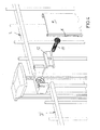
- the support block and the attachment of the grid mats 3 serving clamping block 4 is formed by a cross-sectionally substantially U-shaped plastic element, as can be seen from the Fig. 1 and 2 results.
- the U-web 4a is equipped with a round or square passage 10, which serves on the one hand for the passage of a rivet nut corresponding to this shape for fixing the component 4, on the other hand also allows the passage of a fixing screw 11, with the same time a clamping profile 12 for fixing the hinged mesh mats is fixed to the post 2.
- Fig. 3 Like, for example Fig. 3 can be seen, are the designated 3a horizontal webs of the grid mats 3 on the 4c designated upper edges of the U-leg 4b, by the upwardly facing bead 14, they are secured there. In the mounting position are the vertical bars, in Fig. 3 designated 3b, in the interior of the U-shaped clamping block 4 and can then be secured to the clamping plate 12 by tightening the fixing screw 11.
- the mounting position is approximately from Fig. 6 ,
- cover plate 9 latched into the fixing slots 7 results in a total substantially closed post profile, which is visually very appealing and by suitably tight fit of the cap 15, which also engages with its edge over the sheet 9, the elements are secured.
- FIG. 4 In Fig. 4 and therefore also in connection with the FIGS. 5 and 6 a variant of the fence is shown.
- Fig. 4 left lattice mat, there with 3 ', offset downwards, about to be able to compensate for a terrain gradient.
- the horizontal rods, which are no longer shown there, are then supported on a terminal block positioned further down, which is also not shown in greater detail here.
- the described embodiments of the invention are still to be modified in many ways, without departing from the spirit.
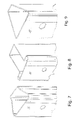
- the invention is not limited to a particular cross-sectional shape of the post 2, as in the Fig. 7 to 9 is shown. It shows Fig. 7 a substantially trapezoidal cross-sectional shape, but with a special transition region from the oblique side walls to the front wall parallel back wall, Fig. 8 a cross-section about T-shaped profile and Fig. 9 a simple trapezoid as a cross-sectional shape.
- the sheet forming the profiles is connected to the front side by laser welding and is equipped, for example, with a covering film in the weld area, in order to prevent any corrosion.
- This masking tape is in Fig. 7 additionally designated 15.
Landscapes
- Engineering & Computer Science (AREA)
- Architecture (AREA)
- Civil Engineering (AREA)
- Structural Engineering (AREA)
- Fencing (AREA)
Abstract
Description
Die Erfindung richtet sich auf einen Zaun mit als Metallhohlprofile ausgebildeten Zaunpfosten und Gittermatten, der im Oberbegriff des Anspruches 1 angegebenen Gattung.The invention is directed to a fence with trained as a metal hollow profiles fence posts and grid mats, the specified in the preamble of claim 1 genus.
Ein derartiges Zaunsystem ist beispielsweise aus dem
Es hat sich gezeigt, dass diese Art der Verbindung eine Fülle von Vorteilen hat, allerdings kann sie insbesondere was die Pfostengestaltung angeht vereinfacht werden. Zum Stand der Technik seien zusätzlich die
Aufgabe der Erfindung ist die Schaffung einer Lösung, mit der die Befestigungstechnik stark vereinfacht wird und die mit möglichst wenig Einzelteilen eine zuverlässige Gitter-/Pfostenverbindung gewährleistet.The object of the invention is to provide a solution with which the fastening technology is greatly simplified and guaranteed with as few items reliable grid / post connection.
Bei einem Zaun der eingangs bezeichneten Art wird diese Aufgabe durch an den Zaunpfosten befestigten, querschnittlich etwa U-förmigen Auflager- und Klemmblöcken aus Kunststoff gelöst, deren von den Zaunpfosten weg weisende Randkanten der U-Schenkel eine in der Gebrauchslage nach oben ausgerichtete Verlängerungswulst aufweisen, wobei die Randkanten der U-Schenkel je einen von ihrer Oberkante ausgehenden, einen Teil der Schenkellänge beaufschlagenden, nach außen weisenden Fixierschlitz aufweisen.In a fence of the type described, this object is achieved by attached to the fence post, cross-sectionally about U-shaped support and clamping blocks made of plastic, their facing away from the fence post edges the U-legs have an extension bead oriented upwardly in the position of use, the peripheral edges of the U-legs each having a fixing slot extending from its upper edge and acting on a part of the leg length pointing outwards.
Aus dem oben an letzter Stelle genannten Gebrauchsmuster sind Montagehilfsmittel bei Zaunpfosten genannt, die in Aufsicht gesehen aus H-förmigen Kunststoffelementen gebildet sind, die an den jeweiligen Zaunpfosten durch einen Kunststoffbügel fixierbar sind, der wiederum durch eine Spreizschraube beaufschlagt ist. Die Erfindung sieht hier ein einfaches Element vor, das mehrere Zusatzfunktionen übernehmen kann, insbesondere dadurch, dass die Randkanten der U-Schenkel je einen von ihrer Oberkante ausgehenden, einen Teil der Schenkellänge beaufschlagenden, nach außen weisenden Fixierschlitz aufweist. Hiermit kann beispielsweise ein entsprechend gestaltetes Abdeckblech gleichzeitig an den Klemmblöcken fixiert werden, wie dies weiter unten beschrieben wird.From the last-mentioned last-mentioned utility model assembly aids are called at fence post, which are seen in supervision formed from H-shaped plastic elements which are fixed to the respective fence post by a plastic strap, which in turn is acted upon by a spreading screw. The invention provides here a simple element, which can take on several additional functions, in particular the fact that the marginal edges of the U-legs each have an outgoing from its upper edge, a part of the leg length acting, outwardly facing fixing slot. Hereby, for example, a correspondingly shaped cover plate can be fixed simultaneously to the terminal blocks, as will be described below.
Weitere Ausgestaltungen der Erfindung ergeben sich aus den sonstigen Unteransprüchen, dabei kann insbesondere vorgesehen sein, dass die Horizontalstäbe der Gittermatten wenigstens unter teilweiser Abstützung an der Verlängerungswulst auf der freien Oberkante des jeweiligen U-Schenkels der Klemmblöcke aufgelegt sind, wobei die außenrandseitigen Vertikalstäbe im Inneren der Klemmblöcke positioniert sind.Further embodiments of the invention will become apparent from the other dependent claims, it may be provided in particular that the horizontal bars of the grid mats are placed at least under partial support on the extension bead on the free upper edge of the respective U-leg of the terminal blocks, the outside edge vertical bars inside Terminal blocks are positioned.
In vorteilhafter weiterer Ausgestaltung kann nach der Erfindung vorgesehen sein, dass die Randkanten der U-Schenkel je einen von ihrer Oberkante ausgehenden, einen Teil der Schenkellänge beaufschlagenden, nach außen weisenden Fixierschlitz aufweisen.In an advantageous further embodiment can be provided according to the invention that the marginal edges of the U-legs each have an outgoing from its upper edge, a part of the leg length acted upon, facing outward Fixierschlitz.
Die Zaunpfosten sind dabei erfindungsgemäß als kaltgewalzte Hohlprofile ausgebildet, wobei die bei der Profilierung aneinanderstoßenden Randkanten der die Profile bildenden Bleche lasergeschweißt sind und wobei in Ausgestaltung die Pfosten querschnittlich etwa trapezförmig oder T-förmig ausgebildet sind, wobei die Trapezform auch geringfügig zusätzlich profiliert sein kann, je nach Einsatzzweck des entsprechenden Pfostens.The fence posts are formed according to the invention as cold rolled hollow sections, wherein the profiled abutting edge edges of the profiles forming sheets are laser welded and wherein in design the posts are formed cross-sectionally approximately trapezoidal or T-shaped, the trapezoidal shape may also be slightly profiled in addition, depending on the purpose of the corresponding post.
Vorteilhaft kann es sein, wenn der Verbindungsbereich zwischen Pfosten und Gittermatten in der Gebrauchslage mit einem Abdeckprofil versehen ist, welches aus einem randseitig nach innen gebördelten Blech gebildet ist, wobei Ausstanzungen der Bördelungsbereiche zur Bildung von Eingriffsstegen in die Fixierschlitze an den Klemmblöcken vorgesehen sind.It may be advantageous if the connection region between the posts and grid mats in the position of use is provided with a cover profile, which is formed from a peripherally flanged plate, wherein punched out the crimping areas are provided for forming engagement webs in the fixing slots on the terminal blocks.
Wie an sich auch schon in der gattungsbildenden Druckschrift vorbeschrieben, sieht die Erfindung auch bei dieser Ausgestaltung vor, dass die Zaunpfosten mit Abdeckkappen ausgerüstet sind, die in der Fertigstellungslage die Randkante des jeweiligen Pfostens übergreifen sowie das eingeklinkte Abdeckblech des Verbindungsbereiches.As already described in the generic document, the invention also provides in this embodiment that the fence posts are equipped with caps that overlap in the finishing position, the peripheral edge of the respective post and the latched cover plate of the connection area.
Weitere Merkmale, Einzelheiten und Vorteile der Erfindung ergeben sich aufgrund der nachfolgenden Beschreibung sowie anhand der Zeichnung. Diese zeigt in
- Fig. 1
- einen Fixierblock nach der Erfindung in räum- licher Darstellung,
- Fig. 2
- den gleichen Fixierblock an einem Zaunpfosten einschließlich vormontierter Abdeckkappe,
- Fig. 3
- in räumlicher Explosionsdarstellung den Kopf- bereich eines Zaunpfostens mit erfindungsgemä- ßem Fixierblock und zwei angedeuteten Gitter- matten in fluchtender Ausrichtung,
- Fig. 4
- in räumlicher Explosionsdarstellung den Kopf- bereich eines Zaunpfostens mit erfindungsgemä- ßem Fixierblock und zwei angedeuteten Gitter- matten in gestufter Ausrichtung,
- Fig. 5
- etwa die Darstellung gemäß
Fig. 4 aus rückwär- tiger Perspektive mit noch nicht vorgesetztem Abdeckblech, - Fig. 6
- einen Zaunpfosten mit positioniertem Abdeck- profil in ähnlicher Darstellung wie
Fig. 5 sowie in den - Fig. 7 bis 9
- als Beispiel unterschiedliche Pfostenquer- schnittsformen in räumlicher Darstellung.
- Fig. 1
- a fixing block according to the invention in spatial representation,
- Fig. 2
- the same fixation block on a fence post including pre-assembled cap,
- Fig. 3
- in a spatial exploded view, the head area of a fence post with a fixing block according to the invention and two indicated grid mats in an aligned orientation,
- Fig. 4
- in a spatial exploded view, the head area of a fence post with a fixing block according to the invention and two indicated grid mats in a stepped orientation,
- Fig. 5
- about the representation according to
Fig. 4 from a retrospective perspective with cover plate not yet installed, - Fig. 6
- a fence post with positioned cover profile in a similar representation as
Fig. 5 as well as in the - Fig. 7 to 9
- as an example different post cross sections in spatial representation.
Bezug nehmend beispielsweise auf
Der der Auflage und der Befestigung der Gittermatten 3 dienende Klemmblock 4 wird von einem querschnittlich im Wesentlichen U-förmigen Kunststoffelement gebildet, wie sich dies aus den
Von dem mit 4a bezeichneten U-Steg weisen zwei U-Schenkel 4b nach außen. Der stirnseitige freie Bereich dieser U-Schenkel 4b ist jeweils so verlängert, dass sich Randkanten 5 bilden mit einer Verlängerungswulst 6, in die in Schwerkraftrichtung von oben gesehen Teilschlitze 7 eingebracht sind zur Aufnahme entsprechender Blechkanten 8 an dem z.B. in
Zentrisch ist der U-Steg 4a mit einem runden oder eckigen Durchgang 10 ausgestattet, der einerseits zum Durchtritt einer dieser Form entsprechenden Nietmutter zur Fixierung des Bauteiles 4 dient, andererseits auch den Durchtritt einer Fixierschraube 11 ermöglicht, mit der gleichzeitig ein Klemmprofil 12 zur Fixierung der eingehängten Gittermatten am Pfosten 2 befestigt wird.Centrally, the U-web 4a is equipped with a round or
Wie beispielsweise aus
Zum Einstülpen bzw. Einrasten der umgefalzten Blechränder 8 in die Fixierschlitze 7 sind Ausstanzungen 13 im Randbereich des Abdeckbleches 9 vorgesehen, die Montagelage ergibt sich etwa aus
Ist das Abdeckblech 9 in die Fixierschlitze 7 eingeklinkt, ergibt sich ein insgesamt im Wesentlichen geschlossenes Pfostenprofil, das optisch äußerst ansprechend ist und durch entsprechend festen Sitz der Abdeckkappe 15, die auch mit ihrem Rand über das Blech 9 greift, sind die Elemente gesichert.If the cover plate 9 latched into the
In
Natürlich sind die beschriebenen Ausführungsbeispiele der Erfindung noch in vielfacher Hinsicht abzuändern, ohne den Grundgedanken zu verlassen. So ist die Erfindung nicht auf eine besondere Querschnittsform der Pfosten 2 beschränkt, wie dies auch in den
Das die Profile bildende Blech ist über Laserschweißung stirnseitig verbunden und z.B. mit einer Abdeckfolie im Schweißnahtbereich ausgerüstet, um so jegliche Korrosion zu verhindern. Dieses Abdeckband ist in
Claims (6)
gekennzeichnet durch
an den Zaunpfosten (2) befestigbaren querschnittlich etwa U-förmigen Auflager- und Klemmblöcken (4) aus Kunststoff, deren von den Zaunpfosten (2) weg weisende Randkanten der U-Schenkel (4b) eine in der Gebrauchslage nach oben ausgerichtete Verlängerungswulst aufweisen, wobei die Randkanten (5) der U-Schenkel (4b) je einen von ihrer Oberkante ausgehenden, einen Teil der Schenkellänge beaufschlagenden, nach außen weisenden Fixierschlitz (7) aufweisen.Fence (1) formed as a metal hollow profiles fence posts (2) and grid mats (3), wherein the grid mats (3) with at least one clamping plate (12) are fixable to the fence post (2),
marked by
on the fence post (2) attachable cross-sectionally approximately U-shaped support and clamping blocks (4) made of plastic, of the fence posts (2) facing away edges of the U-legs (4b) have an upwardly oriented in the use position extension bead, said the marginal edges (5) of the U-legs (4b) each have an outgoing from its upper edge, a part of the leg length acting on, facing outward Fixierschlitz (7).
dadurch gekennzeichnet,
dass die Horizontalstäbe (3a) der Gittermatten (3) wenigstens unter teilweiser Abstützung an der Verlängerungswulst (3,6) auf der freien Oberkante (4c) des jeweiligen U-Schenkels (4b) der Klemmblöcke (4) aufgelegt sind, wobei die außenrandseitigen Vertikalstäbe (3b) im Inneren der Klemmblöcke (4) positioniert sind.Fence according to claim 1,
characterized,
in that the horizontal bars (3a) of the grid mats (3) are at least partially supported on the extension bead (3,6) on the free upper edge (4c) of the respective U-leg (4b) of the clamping blocks (4), wherein the outer edge side vertical bars (3b) are positioned inside the clamping blocks (4).
dadurch gekennzeichnet,
dass die Zaunpfosten (2) als kaltgewalzte Hohlprofile ausgebildet sind, wobei die bei der Profilierung aneinanderstoßenden Randkanten der die Profile bildenden Bleche lasergeschweißt sind.Fence according to claim 1 or 2,
characterized,
in that the fence posts (2) are designed as cold-rolled hollow profiles, wherein the edges of the sheets forming the profiles are laser-welded in the profiling.
dadurch gekennzeichnet,
dass die Zaunpfosten (2) querschnittlich etwa trapezförmig oder T-förmig ausgebildet sind.Fence according to claim 3,
characterized,
that the fence posts (2) are cross-sectionally approximately trapezoidal or T-shaped.
dadurch gekennzeichnet,
dass der Verbindungsbereich zwischen Zaunpfosten (2) und Gittermatten (3) in der Gebrauchslage mit einem Abdeckprofil (9) versehen ist, das aus einem randseitig nach innen gebördelten Blech gebildet ist, wobei Ausstanzungen (13) der Bördelungsbereiche zur Bildung von Eingriffsstegen (8) in die Fixierschlitze (7) an den Klemmblöcken (4) vorgesehen sind.Fence according to one of the preceding claims,
characterized,
in that the connection region between fence post (2) and grid mats (3) in the position of use is provided with a covering profile (9) which is formed from a metal plate which is crimped on the inside, punches (13) of the crimping regions forming engagement webs (8). in the fixing slots (7) on the clamping blocks (4) are provided.
dadurch gekennzeichnet,
dass die Zaunpfosten (2) mit Abdeckkappen (15) ausgerüstet sind, die in der Fertigstellungslage die Randkante des jeweiligen Pfostens (2) übergreifen sowie das eingeklinkte Abdeckblech (9) des Verbindungsbereiches.Fence according to one of the preceding claims,
characterized,
in that the fence posts (2) are equipped with cover caps (15) which in the finishing position overlap the peripheral edge of the respective post (2) and the latched cover plate (9) of the connecting area.
Applications Claiming Priority (1)
| Application Number | Priority Date | Filing Date | Title |
|---|---|---|---|
| DE202007010535U DE202007010535U1 (en) | 2007-07-28 | 2007-07-28 | Fence with trained as metal hollow profiles fence posts and grid mats |
Publications (3)
| Publication Number | Publication Date |
|---|---|
| EP2020473A2 true EP2020473A2 (en) | 2009-02-04 |
| EP2020473A3 EP2020473A3 (en) | 2011-07-20 |
| EP2020473B1 EP2020473B1 (en) | 2013-01-16 |
Family
ID=39432250
Family Applications (1)
| Application Number | Title | Priority Date | Filing Date |
|---|---|---|---|
| EP08010850A Active EP2020473B1 (en) | 2007-07-28 | 2008-06-14 | Fence with hollow metal profiles fence posts and grid mats |
Country Status (2)
| Country | Link |
|---|---|
| EP (1) | EP2020473B1 (en) |
| DE (1) | DE202007010535U1 (en) |
Cited By (5)
| Publication number | Priority date | Publication date | Assignee | Title |
|---|---|---|---|---|
| ES2374385A1 (en) * | 2011-12-12 | 2012-02-16 | Alejandro PROCOARD, S.L. | Pole for a metal enclosure and corresponding enclosure (Machine-translation by Google Translate, not legally binding) |
| ES2374487A1 (en) * | 2011-12-12 | 2012-02-17 | Alejandro PROCOARD, S.L. | Anchoring device for a metal enclosure and corresponding enclosure (Machine-translation by Google Translate, not legally binding) |
| IT201900011796A1 (en) * | 2019-07-15 | 2021-01-15 | Ind I A S P A | FIXING SYSTEM FOR PARAPETS OR FENCES AND RELATED PARAPET OR FENCE |
| WO2022153083A1 (en) * | 2021-01-15 | 2022-07-21 | Ind.I.A. Spa | Fastening system for parapets or fences and related parapet or fence |
| CN114809812A (en) * | 2022-04-19 | 2022-07-29 | 宁波纬诚科技股份有限公司 | Fence net plate and fence system with same |
Families Citing this family (3)
| Publication number | Priority date | Publication date | Assignee | Title |
|---|---|---|---|---|
| DE102020130776A1 (en) | 2020-09-24 | 2022-03-24 | Harhoff's Idee UG (haftungsbeschränkt) | Fence fastening system, fence installation, method of assembly and disassembly |
| DE102022107612A1 (en) | 2022-03-30 | 2023-10-05 | Stamo Verbindungstechnik Gmbh | Clamping plate for mounting grid mats |
| DE202022101706U1 (en) | 2022-03-30 | 2022-04-07 | Stamo Verbindungstechnik Gmbh | Clamping plate for mounting grid mats |
Citations (5)
| Publication number | Priority date | Publication date | Assignee | Title |
|---|---|---|---|---|
| DE8617638U1 (en) | 1986-07-02 | 1986-09-11 | Zapf, Jürgen, 5805 Breckerfeld | Device for connecting fence mesh elements with a fence post |
| DE29906653U1 (en) | 1999-04-15 | 2000-08-24 | Wecolit & Plastic Wesel & Co., 45549 Sprockhövel | Fence attachment with a hollow fence post |
| DE10105483C2 (en) | 2001-02-07 | 2003-06-18 | Gunnebo Wego Ag Sicherheitssys | Fence with grid elements |
| DE202006007695U1 (en) | 2006-05-13 | 2006-09-28 | Cremer, Thomas | Wall holder for flat screen, has supporting units with accommodations for connecting units to attach supporting units at screen and wall, respectively, where supporting units are made up of aluminum, steel or plastic |
| EP1712711A1 (en) | 2005-04-14 | 2006-10-18 | Betafence Holding NV | Fencing system |
Family Cites Families (4)
| Publication number | Priority date | Publication date | Assignee | Title |
|---|---|---|---|---|
| ATE261550T1 (en) * | 2000-12-19 | 2004-03-15 | Moreda Riviere Trefilerias S A | SYSTEM FOR CONNECTING FENCES OR PANELS TO SUPPORT STRUCTURES |
| WO2003040496A1 (en) * | 2001-11-05 | 2003-05-15 | Elkosta Security Systems Gmbh & Co. Kg | Fastening device for fastening grid-like fence sections to a fence post |
| DE20307928U1 (en) * | 2003-05-21 | 2003-07-10 | RK Rose + Krieger GmbH & Co. KG Verbindungs- und Positioniersysteme, 32423 Minden | Fastener device for securing pair of adjacent grilles to fence post, includes holder with grooved bearing block acting as hinge for grille door |
| DE202006007690U1 (en) * | 2005-11-29 | 2007-09-20 | Gebhardt-Stahl Gmbh | Fence made of fence posts and lattice mats |
-
2007
- 2007-07-28 DE DE202007010535U patent/DE202007010535U1/en not_active Expired - Lifetime
-
2008
- 2008-06-14 EP EP08010850A patent/EP2020473B1/en active Active
Patent Citations (5)
| Publication number | Priority date | Publication date | Assignee | Title |
|---|---|---|---|---|
| DE8617638U1 (en) | 1986-07-02 | 1986-09-11 | Zapf, Jürgen, 5805 Breckerfeld | Device for connecting fence mesh elements with a fence post |
| DE29906653U1 (en) | 1999-04-15 | 2000-08-24 | Wecolit & Plastic Wesel & Co., 45549 Sprockhövel | Fence attachment with a hollow fence post |
| DE10105483C2 (en) | 2001-02-07 | 2003-06-18 | Gunnebo Wego Ag Sicherheitssys | Fence with grid elements |
| EP1712711A1 (en) | 2005-04-14 | 2006-10-18 | Betafence Holding NV | Fencing system |
| DE202006007695U1 (en) | 2006-05-13 | 2006-09-28 | Cremer, Thomas | Wall holder for flat screen, has supporting units with accommodations for connecting units to attach supporting units at screen and wall, respectively, where supporting units are made up of aluminum, steel or plastic |
Cited By (5)
| Publication number | Priority date | Publication date | Assignee | Title |
|---|---|---|---|---|
| ES2374385A1 (en) * | 2011-12-12 | 2012-02-16 | Alejandro PROCOARD, S.L. | Pole for a metal enclosure and corresponding enclosure (Machine-translation by Google Translate, not legally binding) |
| ES2374487A1 (en) * | 2011-12-12 | 2012-02-17 | Alejandro PROCOARD, S.L. | Anchoring device for a metal enclosure and corresponding enclosure (Machine-translation by Google Translate, not legally binding) |
| IT201900011796A1 (en) * | 2019-07-15 | 2021-01-15 | Ind I A S P A | FIXING SYSTEM FOR PARAPETS OR FENCES AND RELATED PARAPET OR FENCE |
| WO2022153083A1 (en) * | 2021-01-15 | 2022-07-21 | Ind.I.A. Spa | Fastening system for parapets or fences and related parapet or fence |
| CN114809812A (en) * | 2022-04-19 | 2022-07-29 | 宁波纬诚科技股份有限公司 | Fence net plate and fence system with same |
Also Published As
| Publication number | Publication date |
|---|---|
| EP2020473B1 (en) | 2013-01-16 |
| DE202007010535U1 (en) | 2008-05-21 |
| EP2020473A3 (en) | 2011-07-20 |
Similar Documents
| Publication | Publication Date | Title |
|---|---|---|
| EP2020473B1 (en) | Fence with hollow metal profiles fence posts and grid mats | |
| WO1995014144A1 (en) | Boundary or enclosure fence | |
| EP2631414B1 (en) | Guide rail for vertical awning and vertical awning | |
| EP2836770A2 (en) | Kit for a device for retaining solar elements | |
| DE202006007690U1 (en) | Fence made of fence posts and lattice mats | |
| EP1775416B1 (en) | Fastening system for roller shutter box | |
| DE2033924A1 (en) | Blind strips or leaves | |
| EP3103956B1 (en) | Modular supporting profile with rod recesses | |
| DE202004003897U1 (en) | Fence post has profiled metal post with integral hooks and clamping rail to retain cross bar | |
| EP2508106B1 (en) | Supporting and installation profiles for fixing panels in a shop fitting system | |
| DE202013011807U1 (en) | Support post for a wall or fence as well as wall or fence and wall-fence combination | |
| EP1997770A1 (en) | Elevator door panel | |
| DE202004016002U1 (en) | Facade fixing system | |
| DE202015100108U1 (en) | Holding device for the ends between the bars of a bar grid element interweaved wind and / or privacy profiles | |
| DE202004016546U1 (en) | Structural lining element for a building faade comprises a tarpaulin formed as a component of a blind having a blind box fitting into the structural field and a shaft contained in it | |
| EP2884004A2 (en) | Support post for a wall or a fence and wall or fence and combination of a wall and a fence | |
| DE60019973T2 (en) | HOLLOW PROFILE | |
| DE29503889U1 (en) | Burglar-resistant grille for wall openings with an additional crossbar | |
| DE102005055061B4 (en) | Fastening system for security fences | |
| DE2556401C3 (en) | Containers for compost production | |
| DE202017101876U1 (en) | Spacer for placement between angular posts and bar grate mats of a fence attached thereto | |
| DE202017103320U1 (en) | fence system | |
| DE6915270U (en) | SUN AND COVER PLATE | |
| DE3039612A1 (en) | Flat roof verge cladding unit - has flat strips clamped between top and bottom rails linked by overlapping plates | |
| DE102010017546A1 (en) | Add-on construction |
Legal Events
| Date | Code | Title | Description |
|---|---|---|---|
| PUAI | Public reference made under article 153(3) epc to a published international application that has entered the european phase |
Free format text: ORIGINAL CODE: 0009012 |
|
| AK | Designated contracting states |
Kind code of ref document: A2 Designated state(s): AT BE BG CH CY CZ DE DK EE ES FI FR GB GR HR HU IE IS IT LI LT LU LV MC MT NL NO PL PT RO SE SI SK TR |
|
| AX | Request for extension of the european patent |
Extension state: AL BA MK RS |
|
| PUAL | Search report despatched |
Free format text: ORIGINAL CODE: 0009013 |
|
| AK | Designated contracting states |
Kind code of ref document: A3 Designated state(s): AT BE BG CH CY CZ DE DK EE ES FI FR GB GR HR HU IE IS IT LI LT LU LV MC MT NL NO PL PT RO SE SI SK TR |
|
| AX | Request for extension of the european patent |
Extension state: AL BA MK RS |
|
| 17P | Request for examination filed |
Effective date: 20111028 |
|
| AKX | Designation fees paid |
Designated state(s): AT BE BG CH CY CZ DE DK EE ES FI FR GB GR HR HU IE IS IT LI LT LU LV MC MT NL NO PL PT RO SE SI SK TR |
|
| REG | Reference to a national code |
Ref country code: DE Ref legal event code: R079 Ref document number: 502008009108 Country of ref document: DE Free format text: PREVIOUS MAIN CLASS: E04H0017160000 Ipc: E04H0017200000 |
|
| RIC1 | Information provided on ipc code assigned before grant |
Ipc: E04H 17/16 20060101ALI20120529BHEP Ipc: E04H 17/20 20060101AFI20120529BHEP |
|
| GRAP | Despatch of communication of intention to grant a patent |
Free format text: ORIGINAL CODE: EPIDOSNIGR1 |
|
| GRAS | Grant fee paid |
Free format text: ORIGINAL CODE: EPIDOSNIGR3 |
|
| GRAA | (expected) grant |
Free format text: ORIGINAL CODE: 0009210 |
|
| AK | Designated contracting states |
Kind code of ref document: B1 Designated state(s): AT BE BG CH CY CZ DE DK EE ES FI FR GB GR HR HU IE IS IT LI LT LU LV MC MT NL NO PL PT RO SE SI SK TR |
|
| REG | Reference to a national code |
Ref country code: GB Ref legal event code: FG4D Free format text: NOT ENGLISH |
|
| REG | Reference to a national code |
Ref country code: CH Ref legal event code: EP |
|
| REG | Reference to a national code |
Ref country code: IE Ref legal event code: FG4D Free format text: LANGUAGE OF EP DOCUMENT: GERMAN |
|
| REG | Reference to a national code |
Ref country code: AT Ref legal event code: REF Ref document number: 594018 Country of ref document: AT Kind code of ref document: T Effective date: 20130215 Ref country code: CH Ref legal event code: EP |
|
| REG | Reference to a national code |
Ref country code: DE Ref legal event code: R096 Ref document number: 502008009108 Country of ref document: DE Effective date: 20130314 |
|
| REG | Reference to a national code |
Ref country code: NL Ref legal event code: VDEP Effective date: 20130116 |
|
| REG | Reference to a national code |
Ref country code: LT Ref legal event code: MG4D |
|
| PG25 | Lapsed in a contracting state [announced via postgrant information from national office to epo] |
Ref country code: ES Free format text: LAPSE BECAUSE OF FAILURE TO SUBMIT A TRANSLATION OF THE DESCRIPTION OR TO PAY THE FEE WITHIN THE PRESCRIBED TIME-LIMIT Effective date: 20130427 Ref country code: IS Free format text: LAPSE BECAUSE OF FAILURE TO SUBMIT A TRANSLATION OF THE DESCRIPTION OR TO PAY THE FEE WITHIN THE PRESCRIBED TIME-LIMIT Effective date: 20130516 Ref country code: NO Free format text: LAPSE BECAUSE OF FAILURE TO SUBMIT A TRANSLATION OF THE DESCRIPTION OR TO PAY THE FEE WITHIN THE PRESCRIBED TIME-LIMIT Effective date: 20130416 Ref country code: BG Free format text: LAPSE BECAUSE OF FAILURE TO SUBMIT A TRANSLATION OF THE DESCRIPTION OR TO PAY THE FEE WITHIN THE PRESCRIBED TIME-LIMIT Effective date: 20130416 Ref country code: SE Free format text: LAPSE BECAUSE OF FAILURE TO SUBMIT A TRANSLATION OF THE DESCRIPTION OR TO PAY THE FEE WITHIN THE PRESCRIBED TIME-LIMIT Effective date: 20130116 Ref country code: LT Free format text: LAPSE BECAUSE OF FAILURE TO SUBMIT A TRANSLATION OF THE DESCRIPTION OR TO PAY THE FEE WITHIN THE PRESCRIBED TIME-LIMIT Effective date: 20130116 |
|
| PG25 | Lapsed in a contracting state [announced via postgrant information from national office to epo] |
Ref country code: NL Free format text: LAPSE BECAUSE OF FAILURE TO SUBMIT A TRANSLATION OF THE DESCRIPTION OR TO PAY THE FEE WITHIN THE PRESCRIBED TIME-LIMIT Effective date: 20130116 Ref country code: PT Free format text: LAPSE BECAUSE OF FAILURE TO SUBMIT A TRANSLATION OF THE DESCRIPTION OR TO PAY THE FEE WITHIN THE PRESCRIBED TIME-LIMIT Effective date: 20130516 Ref country code: FI Free format text: LAPSE BECAUSE OF FAILURE TO SUBMIT A TRANSLATION OF THE DESCRIPTION OR TO PAY THE FEE WITHIN THE PRESCRIBED TIME-LIMIT Effective date: 20130116 Ref country code: GR Free format text: LAPSE BECAUSE OF FAILURE TO SUBMIT A TRANSLATION OF THE DESCRIPTION OR TO PAY THE FEE WITHIN THE PRESCRIBED TIME-LIMIT Effective date: 20130417 Ref country code: SI Free format text: LAPSE BECAUSE OF FAILURE TO SUBMIT A TRANSLATION OF THE DESCRIPTION OR TO PAY THE FEE WITHIN THE PRESCRIBED TIME-LIMIT Effective date: 20130116 Ref country code: PL Free format text: LAPSE BECAUSE OF FAILURE TO SUBMIT A TRANSLATION OF THE DESCRIPTION OR TO PAY THE FEE WITHIN THE PRESCRIBED TIME-LIMIT Effective date: 20130116 Ref country code: LV Free format text: LAPSE BECAUSE OF FAILURE TO SUBMIT A TRANSLATION OF THE DESCRIPTION OR TO PAY THE FEE WITHIN THE PRESCRIBED TIME-LIMIT Effective date: 20130116 |
|
| PG25 | Lapsed in a contracting state [announced via postgrant information from national office to epo] |
Ref country code: HR Free format text: LAPSE BECAUSE OF FAILURE TO SUBMIT A TRANSLATION OF THE DESCRIPTION OR TO PAY THE FEE WITHIN THE PRESCRIBED TIME-LIMIT Effective date: 20130116 |
|
| PG25 | Lapsed in a contracting state [announced via postgrant information from national office to epo] |
Ref country code: RO Free format text: LAPSE BECAUSE OF FAILURE TO SUBMIT A TRANSLATION OF THE DESCRIPTION OR TO PAY THE FEE WITHIN THE PRESCRIBED TIME-LIMIT Effective date: 20130116 Ref country code: DK Free format text: LAPSE BECAUSE OF FAILURE TO SUBMIT A TRANSLATION OF THE DESCRIPTION OR TO PAY THE FEE WITHIN THE PRESCRIBED TIME-LIMIT Effective date: 20130116 Ref country code: SK Free format text: LAPSE BECAUSE OF FAILURE TO SUBMIT A TRANSLATION OF THE DESCRIPTION OR TO PAY THE FEE WITHIN THE PRESCRIBED TIME-LIMIT Effective date: 20130116 Ref country code: CZ Free format text: LAPSE BECAUSE OF FAILURE TO SUBMIT A TRANSLATION OF THE DESCRIPTION OR TO PAY THE FEE WITHIN THE PRESCRIBED TIME-LIMIT Effective date: 20130116 Ref country code: EE Free format text: LAPSE BECAUSE OF FAILURE TO SUBMIT A TRANSLATION OF THE DESCRIPTION OR TO PAY THE FEE WITHIN THE PRESCRIBED TIME-LIMIT Effective date: 20130116 |
|
| PLBE | No opposition filed within time limit |
Free format text: ORIGINAL CODE: 0009261 |
|
| STAA | Information on the status of an ep patent application or granted ep patent |
Free format text: STATUS: NO OPPOSITION FILED WITHIN TIME LIMIT |
|
| PG25 | Lapsed in a contracting state [announced via postgrant information from national office to epo] |
Ref country code: CY Free format text: LAPSE BECAUSE OF FAILURE TO SUBMIT A TRANSLATION OF THE DESCRIPTION OR TO PAY THE FEE WITHIN THE PRESCRIBED TIME-LIMIT Effective date: 20130116 |
|
| 26N | No opposition filed |
Effective date: 20131017 |
|
| PG25 | Lapsed in a contracting state [announced via postgrant information from national office to epo] |
Ref country code: IT Free format text: LAPSE BECAUSE OF FAILURE TO SUBMIT A TRANSLATION OF THE DESCRIPTION OR TO PAY THE FEE WITHIN THE PRESCRIBED TIME-LIMIT Effective date: 20130116 |
|
| PG25 | Lapsed in a contracting state [announced via postgrant information from national office to epo] |
Ref country code: MC Free format text: LAPSE BECAUSE OF FAILURE TO SUBMIT A TRANSLATION OF THE DESCRIPTION OR TO PAY THE FEE WITHIN THE PRESCRIBED TIME-LIMIT Effective date: 20130116 |
|
| REG | Reference to a national code |
Ref country code: DE Ref legal event code: R097 Ref document number: 502008009108 Country of ref document: DE Effective date: 20131017 |
|
| REG | Reference to a national code |
Ref country code: IE Ref legal event code: MM4A |
|
| PG25 | Lapsed in a contracting state [announced via postgrant information from national office to epo] |
Ref country code: IE Free format text: LAPSE BECAUSE OF NON-PAYMENT OF DUE FEES Effective date: 20130614 |
|
| PGFP | Annual fee paid to national office [announced via postgrant information from national office to epo] |
Ref country code: GB Payment date: 20140620 Year of fee payment: 7 |
|
| PGFP | Annual fee paid to national office [announced via postgrant information from national office to epo] |
Ref country code: AT Payment date: 20140618 Year of fee payment: 7 Ref country code: CH Payment date: 20140620 Year of fee payment: 7 |
|
| PGFP | Annual fee paid to national office [announced via postgrant information from national office to epo] |
Ref country code: BE Payment date: 20140618 Year of fee payment: 7 |
|
| PGFP | Annual fee paid to national office [announced via postgrant information from national office to epo] |
Ref country code: FR Payment date: 20140617 Year of fee payment: 7 |
|
| PG25 | Lapsed in a contracting state [announced via postgrant information from national office to epo] |
Ref country code: MT Free format text: LAPSE BECAUSE OF FAILURE TO SUBMIT A TRANSLATION OF THE DESCRIPTION OR TO PAY THE FEE WITHIN THE PRESCRIBED TIME-LIMIT Effective date: 20130116 |
|
| PG25 | Lapsed in a contracting state [announced via postgrant information from national office to epo] |
Ref country code: TR Free format text: LAPSE BECAUSE OF FAILURE TO SUBMIT A TRANSLATION OF THE DESCRIPTION OR TO PAY THE FEE WITHIN THE PRESCRIBED TIME-LIMIT Effective date: 20130116 |
|
| PG25 | Lapsed in a contracting state [announced via postgrant information from national office to epo] |
Ref country code: HU Free format text: LAPSE BECAUSE OF FAILURE TO SUBMIT A TRANSLATION OF THE DESCRIPTION OR TO PAY THE FEE WITHIN THE PRESCRIBED TIME-LIMIT; INVALID AB INITIO Effective date: 20080614 Ref country code: LU Free format text: LAPSE BECAUSE OF NON-PAYMENT OF DUE FEES Effective date: 20130614 |
|
| REG | Reference to a national code |
Ref country code: CH Ref legal event code: PL |
|
| REG | Reference to a national code |
Ref country code: AT Ref legal event code: MM01 Ref document number: 594018 Country of ref document: AT Kind code of ref document: T Effective date: 20150614 |
|
| GBPC | Gb: european patent ceased through non-payment of renewal fee |
Effective date: 20150614 |
|
| REG | Reference to a national code |
Ref country code: FR Ref legal event code: ST Effective date: 20160229 |
|
| PG25 | Lapsed in a contracting state [announced via postgrant information from national office to epo] |
Ref country code: LI Free format text: LAPSE BECAUSE OF NON-PAYMENT OF DUE FEES Effective date: 20150630 Ref country code: CH Free format text: LAPSE BECAUSE OF NON-PAYMENT OF DUE FEES Effective date: 20150630 Ref country code: GB Free format text: LAPSE BECAUSE OF NON-PAYMENT OF DUE FEES Effective date: 20150614 |
|
| PG25 | Lapsed in a contracting state [announced via postgrant information from national office to epo] |
Ref country code: FR Free format text: LAPSE BECAUSE OF NON-PAYMENT OF DUE FEES Effective date: 20150630 Ref country code: AT Free format text: LAPSE BECAUSE OF NON-PAYMENT OF DUE FEES Effective date: 20150614 |
|
| PG25 | Lapsed in a contracting state [announced via postgrant information from national office to epo] |
Ref country code: BE Free format text: LAPSE BECAUSE OF NON-PAYMENT OF DUE FEES Effective date: 20150630 |
|
| PGFP | Annual fee paid to national office [announced via postgrant information from national office to epo] |
Ref country code: DE Payment date: 20240229 Year of fee payment: 17 |