EP2884004A2 - Support post for a wall or a fence and wall or fence and combination of a wall and a fence - Google Patents
Support post for a wall or a fence and wall or fence and combination of a wall and a fence Download PDFInfo
- Publication number
- EP2884004A2 EP2884004A2 EP14194416.5A EP14194416A EP2884004A2 EP 2884004 A2 EP2884004 A2 EP 2884004A2 EP 14194416 A EP14194416 A EP 14194416A EP 2884004 A2 EP2884004 A2 EP 2884004A2
- Authority
- EP
- European Patent Office
- Prior art keywords
- wall
- support post
- fence
- modules
- leg
- Prior art date
- Legal status (The legal status is an assumption and is not a legal conclusion. Google has not performed a legal analysis and makes no representation as to the accuracy of the status listed.)
- Withdrawn
Links
Images


Classifications
-
- E—FIXED CONSTRUCTIONS
- E02—HYDRAULIC ENGINEERING; FOUNDATIONS; SOIL SHIFTING
- E02B—HYDRAULIC ENGINEERING
- E02B3/00—Engineering works in connection with control or use of streams, rivers, coasts, or other marine sites; Sealings or joints for engineering works in general
- E02B3/04—Structures or apparatus for, or methods of, protecting banks, coasts, or harbours
- E02B3/10—Dams; Dykes; Sluice ways or other structures for dykes, dams, or the like
- E02B3/106—Temporary dykes
-
- E—FIXED CONSTRUCTIONS
- E04—BUILDING
- E04H—BUILDINGS OR LIKE STRUCTURES FOR PARTICULAR PURPOSES; SWIMMING OR SPLASH BATHS OR POOLS; MASTS; FENCING; TENTS OR CANOPIES, IN GENERAL
- E04H17/00—Fencing, e.g. fences, enclosures, corrals
- E04H17/14—Fences constructed of rigid elements, e.g. with additional wire fillings or with posts
- E04H17/20—Posts therefor
-
- E—FIXED CONSTRUCTIONS
- E02—HYDRAULIC ENGINEERING; FOUNDATIONS; SOIL SHIFTING
- E02B—HYDRAULIC ENGINEERING
- E02B3/00—Engineering works in connection with control or use of streams, rivers, coasts, or other marine sites; Sealings or joints for engineering works in general
- E02B3/16—Sealings or joints
-
- E—FIXED CONSTRUCTIONS
- E04—BUILDING
- E04H—BUILDINGS OR LIKE STRUCTURES FOR PARTICULAR PURPOSES; SWIMMING OR SPLASH BATHS OR POOLS; MASTS; FENCING; TENTS OR CANOPIES, IN GENERAL
- E04H17/00—Fencing, e.g. fences, enclosures, corrals
- E04H17/14—Fences constructed of rigid elements, e.g. with additional wire fillings or with posts
- E04H17/16—Fences constructed of rigid elements, e.g. with additional wire fillings or with posts using prefabricated panel-like elements, e.g. wired frames
- E04H17/168—Fences constructed of rigid elements, e.g. with additional wire fillings or with posts using prefabricated panel-like elements, e.g. wired frames using panels fitted in grooves of posts
-
- E—FIXED CONSTRUCTIONS
- E04—BUILDING
- E04H—BUILDINGS OR LIKE STRUCTURES FOR PARTICULAR PURPOSES; SWIMMING OR SPLASH BATHS OR POOLS; MASTS; FENCING; TENTS OR CANOPIES, IN GENERAL
- E04H9/00—Buildings, groups of buildings or shelters adapted to withstand or provide protection against abnormal external influences, e.g. war-like action, earthquake or extreme climate
- E04H9/14—Buildings, groups of buildings or shelters adapted to withstand or provide protection against abnormal external influences, e.g. war-like action, earthquake or extreme climate against other dangerous influences, e.g. tornadoes, floods
- E04H9/145—Floods
-
- E—FIXED CONSTRUCTIONS
- E02—HYDRAULIC ENGINEERING; FOUNDATIONS; SOIL SHIFTING
- E02B—HYDRAULIC ENGINEERING
- E02B7/00—Barrages or weirs; Layout, construction, methods of, or devices for, making same
- E02B7/20—Movable barrages; Lock or dry-dock gates
- E02B7/22—Stop log dams; Emergency gates
-
- E—FIXED CONSTRUCTIONS
- E02—HYDRAULIC ENGINEERING; FOUNDATIONS; SOIL SHIFTING
- E02B—HYDRAULIC ENGINEERING
- E02B7/00—Barrages or weirs; Layout, construction, methods of, or devices for, making same
- E02B7/20—Movable barrages; Lock or dry-dock gates
- E02B7/54—Sealings for gates
-
- Y—GENERAL TAGGING OF NEW TECHNOLOGICAL DEVELOPMENTS; GENERAL TAGGING OF CROSS-SECTIONAL TECHNOLOGIES SPANNING OVER SEVERAL SECTIONS OF THE IPC; TECHNICAL SUBJECTS COVERED BY FORMER USPC CROSS-REFERENCE ART COLLECTIONS [XRACs] AND DIGESTS
- Y02—TECHNOLOGIES OR APPLICATIONS FOR MITIGATION OR ADAPTATION AGAINST CLIMATE CHANGE
- Y02A—TECHNOLOGIES FOR ADAPTATION TO CLIMATE CHANGE
- Y02A50/00—TECHNOLOGIES FOR ADAPTATION TO CLIMATE CHANGE in human health protection, e.g. against extreme weather
Definitions
- the invention relates to a support post for a wall, in particular flood protection wall, or a fence having at least two mutually parallel and spaced apart legs between which an edge portion of at least one wall element or a fence element can be arranged to set up the wall or fence.
- the invention relates to a wall, in particular flood protection wall, or a fence or a flood protection wall-fence combination, comprising at least two mutually sealed and positively connectable wall modules or fence modules and at least two support posts on which the wall modules or fence modules for installation the wall or the fence can be arranged, wherein on a wall module or fence module, a spring or a projection and on the other wall module or fence module is formed a complementary to the tongue groove or recess, whereby the wall modules or fence modules are connected to each other ,
- the invention relates to a wall, in particular flood protection wall, or a fence, comprising at least two mutually sealed interconnected wall modules or fence modules and at least two support posts on which the wall modules or fence modules for installation of the wall or the fence can be arranged.
- a mobile flood control wall is known from a plurality of substantially water impermeable composite elements which are oriented vertically Fastening fastened and connectable to form a tongue and groove connection.
- Such a flood protection wall may have a plurality of support posts, which are laterally provided with U-shaped receptacles can be inserted into the edge portions of wall elements. At the support posts usually seals are arranged, which cooperate for sealing such a flood protection wall with the imported into the receptacles edge portions of the wall elements.
- the wall elements When installing a corresponding flood protection wall, the wall elements are inserted from above between two mutually adjacent support posts, whereby the edge portions are inserted into the receptacles on the support post.
- the wall element comes almost inevitably in contact with the seals, whereby the seals can be damaged, which in turn leads to leaks in a suitably trained flood protection wall.
- This problem occurs in particular in the introduction of relatively large wall elements, for example by means of a crane, between two support posts.
- the object of the invention is to provide both a stationary and mobile deployable wall or a both stationary and mobile deployable fence or fence-wall combination, which or in its shape in a simple manner can be changed and at the same time as highly reliable flood protection can be used.
- the object of the invention is also to provide a way for reliable and permanent sealing of walls, especially flood walls.
- a support post for a wall, in particular flood protection wall comprising at least two mutually parallel and spaced apart legs between which an edge portion of at least one wall element can be arranged to set up the wall, and at least one extending parallel to the longitudinal extent of the support post between a leg and the edge portion of the wall element in the application arranged sealing element, characterized by at least one parallel to the longitudinal extent of the support post extending between the leg and the edge portion of the wall element in the application arranged separate profile, on whose side facing away from the leg, the sealing element is arranged, wherein the formed from the sealing element and the separate profile assembly is formed such that they zw to generate a force acting on the sealing element clamping force transverse to the longitudinal extent of the support post zw is introduced the leg and the edge portion of the wall element in the application case.
- the sealing element is not arranged on a leg, but on a separately formed profile and can thus be arranged after insertion of an edge portion of a wall element between the two legs of the support post between the respective leg and the edge portion. Consequently, it can not come to a contact between the edge portion and sealing element in the introduction of the edge portion between the two legs, so that a resulting damage to the sealing element, as is known from the prior art, can not occur.
- a wall, in particular flood protection wall created, which is reliably and permanently sealed.
- the support post can also have two or more pairs of legs arranged parallel to one another and at a distance from one another, between which an edge section of at least one wall element can be arranged for erecting the wall. Also, between each leg and an edge portion of a wall element, a parallel to the longitudinal extent of the support post can be arranged extending sealing element.
- the support post may also have two or more parallel to the longitudinal extent of the support post extending between a leg and an edge portion of the wall element in the case of use arranged separate profiles, on whose respective side facing away from a leg each have a sealing element is arranged.
- the sealing element and the separate profile extend over the entire length of the respective leg.
- the sealing element may be formed of an elastomer, in particular of rubber.
- a receptacle for fixing the sealing element can be arranged relative to the separate profile in which a part of the sealing element engages positively.
- the sealing element is arranged interchangeably on the receptacle, so that by the respective choice of the type of sealing element of the support post can be adapted to the particular circumstances and in the case of a damaged sealing element a simple and quick replacement can be done against a new sealing element.
- the support post has at least one clamping device with at least one clamping member, which is designed such that a part of the introduced between the leg and the edge portion of the wall element separate profile between the clamping member and the leg can be clamped.
- the separate profile, and with it the sealing element arranged thereon can be fixed to the rest of the support post in its intended position. This is accompanied by a permanent and reliable sealing of a correspondingly equipped wall, in particular flood protection wall.
- the clamping member has a free end portion and an end portion connected to the separate profile or web connecting the two legs, the clamping member being formed such that at least a portion of the free end portion is inserted between the leg and the edge portion of the wall member separate profile is in physical contact with a formed on the separate profile clamping portion, whereby the free end portion is acted upon by the clamping portion in the direction of the leg with a clamping force.
- a clamping force is necessarily generated in the arrangement of the separate profile, which can be transmitted via the clamping member on the clamped by the clamping member of the separate profile.
- the free end portion of the clamping member and the clamping portion of the separate profile chamfers may be arranged to promote the interaction of the clamping member and clamping portion.
- the free end portion of the clamping member is formed as directed away from the leg bend. This represents an optimum embodiment for generating the clamping force acting on the clamping member or the part of the separate profile.
- the clamping member may be rounded or the like formed.
- a receptacle is formed between the connected to the separate profile or the web end portion and the leg into which the part of the separate profile is inserted, wherein on the side facing away from the leg of the free end of the between the clamping member and the leg can be clamped part of the separate profile is arranged a chamfer.
- the bevel facilitates the introduction of the part of the separate profile into the receptacle.
- the chamfer may be formed as a chamfer, rounding or the like.
- a further advantageous embodiment provides that at least one sealing lip is arranged on the side of the sealing element facing away from the separate profile. As a result, the sealing effect of the sealing element is increased. On the side facing away from the separate profile side of the sealing element and two or more sealing lips may be arranged.
- the support post on at least one parallel and spaced from the longitudinal extension of the support post can be arranged, connectable with the legs stiffening profile.
- This stiffening profile can give the support post high rigidity properties.
- the stiffening profile may be formed as a hollow profile and / or honeycomb in cross-section.
- the support post comprises at least one connectable with at least one leg and / or the stiffening profile cover. This can be from a appropriately formed wall in the viewer caused visual impression can be improved by the wall is given a more aesthetic appearance.
- the support post has at least one securable locking unit, with which the separate profile and the edge portion of the wall element can be locked to at least one leg.
- an anti-theft device can be formed, since the separate profile can not be removed from the rest of the support profile when the locking device is secured.
- the lockable locking unit may include a cylinder lock, a pressure cylinder, a mortise lock, a bolt with padlock or the like.
- a corresponding locking device can also be used in otherwise modularly constructed support post to form a corresponding anti-theft device.
- a burglary protection for houses and buildings are formed when a door gate, or window opening in a wall of a house or building is closed by such a wall. It is not possible for unauthorized persons, due to the locking units of the components of the flood protection wall, to dismantle a corresponding wall and thus gain access to a house or building. This is an advantage as it usually comes with a flood hazard to evacuation of houses and buildings. As a result, unauthorized persons could get unhindered access to empty houses and buildings, but this can be reliably prevented with the support post according to the invention or a flood protection wall equipped therewith.
- a self-inventive inventive support post for a wall, especially flood protection wall, or a fence is proposed at this point.
- This may also have the features of the invention, but also only at least two mutually parallel and spaced apart legs have, between which for setting up the wall or the fence, an edge portion of at least one wall element or a fence element can be arranged, and which at least one adjusting device comprises, which is formed and connected to the legs, that with her the distance of the legs from each other for clamping the arranged between the legs edge portion between the legs is variable.
- Conventional support posts, which have an adjusting device for varying the distance between the legs usually only work if edge sections of a wall element or fence element are arranged on both sides.
- the proposed here also independently inventive support post can also have only two legs and still allow a secure sealing between the support post and the wall element or fence element, because he has next to the adjusting device at least one guide device which is designed and arranged such that with her the at least one leg whose distance to the base unit is variable, during a movement of this leg is forced relative to the base unit.
- This ensures the application of a desired clamping force with a variation of the distance of the legs from each other, in particular because the positive guidance of the respective clamping force reducing tilting of the leg is prevented.
- both legs can be adjusted relative to the base unit.
- the support post may have a separate guide device for each leg or a common guide device for two or more legs.
- positive guidance means a device or feature which constitutes an additional guide next to the setting unit and enables a secure clamping of a rim portion on only one side of the support post.
- the forced operation is realized by a pin which engages in a recess.
- the adjusting device has at least one screw mechanism.
- the adjusting mechanism can also have two or more screw mechanisms. About the screw mechanism, the distance between the legs of each other can vary very accurately, while at the same time a generation of sufficient clamping forces in a simple manner is possible.
- At least one of at least one leg at least over a part of the length of the leg extending seal disposed on a side facing the respective other leg.
- the leg provided with the seal can be sealed against a wall element or fence element.
- a corresponding seal can be arranged on each leg to increase the tightness of a correspondingly formed wall or a correspondingly formed fence.
- two or more parallel seals may be arranged on one leg.
- the seal extends over the entire length of the leg.
- the seal may be formed of an elastomer, in particular of rubber.
- At least one receptacle for holding the seal is arranged on at least one leg.
- the receptacle may allow a fixation of the seal relative to the respective leg.
- the seal is arranged interchangeably on the receptacle, so that the respective choice of the type of seal the support post to the particular circumstances is customizable and in the case of a damaged seal a simple and quick replacement can be done against a new seal.
- the support post has at least one extending in the longitudinal direction of the support post base unit on which the legs are arranged non-destructively detachable, wherein the distance from at least one leg to the base unit by means of the adjusting device is variable.
- the support post can have two corresponding pairs of legs, wherein between each pair an edge portion of a wall element or fence element can be clamped.
- a corresponding support post is used as the end post of a wall or fence, the unneeded pair of legs can be nondestructively detached from and removed from the support post to create a more aesthetic appearance of the wall or fence.
- the screw mechanism of the adjusting mechanism may be partially disposed and guided on the base unit.
- the legs are each connected via a press fit frictionally connected to the base unit or part of this.
- a wall or a fence can thus be provided as a kit, which can be erected, displaced and shaped in its shape in particular by a consumer in a simple manner with a suitable and desired shape.
- the wall or the fence can be used stationary and changed in its shape.
- the wall or the fence can be used mobile, in particular to form a flood protection wall, since the installation of the wall or the fence is easy and fast.
- a fence with a desired shape can also be set up by means of support posts according to the invention, which can be rebuilt if necessary in a simple manner and quickly to a flood protection wall, and vice versa.
- a change in the shape of such a wall or such a fence can also be made for purely aesthetic reasons.
- the shape of a wall or a fence using support posts according to the invention can be adapted in a simple manner to the respective requirements, for example with respect to the impermeability to certain species.
- a further advantageous embodiment for all types of support posts described here provides that the support post has at least one bracing device, which is designed and arranged such that with it the wall element or the fence element can be acted upon with a force directed to the ground.
- the at least one wall element or fence element can be pressed against the ground in order, for example, to form a flood protection wall, without water being able to pass through the wall or the fence between the wall element or fence element and the floor.
- the bracing means may comprise at least one screw mechanism arranged for bracing.
- a wall, in particular flood protection wall, or a fence or a protective wall-fence combination comprising at least two mutually sealed and positively connectable wall modules or fence modules and at least two support posts on which the wall modules or fence modules for setting up the Wall or the fence can be arranged, wherein at least one module composed by at least two sub-modules by means of a arranged along a longitudinal side of the sub-module clip connection is, and wherein preferably the Untermodululdichtung is not visible to the outside.
- composition of a module by two sub-modules by means of a clip connection and at least one inner seal it is possible to provide a flood protection wall, a fence or a fence-wall combination, which (r) depending on the application - whether stationary or mobile - is composable and is particularly resistant to wear by the inner seal (s).
- the clip connection also represents a simple connectivity of the sub-modules, especially since no tool must be used to connect the sub-modules in a pure clip connection.
- only relatively small submodules have to be stored in order to be able to form, for example, a flood protection wall.
- a suitable pre-assembly of wall modules or fence modules can be made, for example, to be able to set up a flood protection wall faster at the site.
- the sub-modules are not only positively connected to each other via a clip connection, but also still positively.
- a non-positive connection is preferably formed in that the latching projection of the clip connection arranged along a longitudinal side of a sub-module, which latching recess is arranged in a latching recess arranged along a longitudinal side of a further submodule engages, is braced by a screw, a pin or by any other suitable means against the release direction of the clip connection.
- a screw channel is formed by the latching projection and the latching recess of the sub-modules, which is widened by inserting a screw, whereby the latching projection of the sub-module is braced against the release direction of the clip connection.
- an inventive aspect independent of the flood protection wall, the fence or the wall-fence combination is a profile which has at least one latching recess described above and / or or a snap-in projection for a clip connection, which is designed so that when joining the clip connection, a channel is formed, which is suitable for inserting a screw, a pin or other suitable means and whereby the locking projection of the profile against the loosening of the Clip connection is clamped.
- the wall is constructed in accordance with one embodiment of sub-modules, which have both a latching projection, as well as a latching recess. Accordingly, the wall is - apart from a bottom profile and optionally an upper end profile - formed by a single module later inseparable, which is composed of a plurality of sub-modules.
- a module is preferably formed by at least two sub-modules, one of which has a latching recess along one end face and has a spring or groove on its opposite end face, which has is designed to be able to engage in the spring or groove of another module and to enter into a detachable and sealed connection with this.
- Another sub-module has at the same time a latching projection on one end face and on its opposite end face a spring or groove which is adapted to engage in the spring or groove of another module and to enter into a detachable and sealed connection.
- the Klips and screw connection described in particular for the connection of profiles can therefore be used not only particularly advantageous for connecting the submodules of the flood protection wall, but also, for example, for frames, doors, windows, exhibition stands and all other constructions, where preferably profiles for producing a mechanical support or structure are connected.
- the wall modules or fence modules for the mobile variant of the flood protection wall are the same, wherein on each wall module or fence module on a front side a spring and an opposite end face a groove is arranged.
- This requires the production of only a single wall module or fence module, which reduces manufacturing costs.
- three or more equally trained wall modules or fence modules for setting up a wall or a fence can be connected to each other in a simple manner.
- the wall modules are constructed symmetrically in cross section beyond. This has the advantage that you do not have to pay attention to the construction of a fence or a flood protection wall, which side of the fence module should face the water and which should point in the other direction.
- At least one support post according to one of the aforementioned embodiments of the support post or any combination thereof, and forms together with the modules composed of sub-modules a particularly preferred embodiment of the flood protection wall, the fence or the wall-fence combination.
- a wall, in particular flood protection wall, or a fence proposed comprising at least two mutually sealed interconnected wall modules or fence modules and at least two support posts on which the wall modules or fence modules for installation of the wall or the fence can be arranged, characterized characterized in that at least one support post according to one of the aforementioned embodiments of the support post or any combination thereof are formed.
- the invention also relates to a wall module, which is composed of two sub-modules, which are preferably non-positively and positively connected with one another Klips- and screw and having at least one, but preferably two inner seal (s).
- the wall module has a groove and a spring and is preferably constructed symmetrically in cross section.
- the wall module has a bracing device, which makes it possible to brace the wall modules with respect to the posts and / or with respect to the floor.
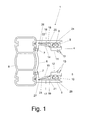
- the support post 1 further comprises two parallel to the longitudinal extent of the support post 1 each extending between a leg 2 and 3 and the edge portion 31 and 32 of the wall element 30 arranged separate profiles 9 and 10 respectively.
- one of the sealing elements 4 and 5 is arranged in each case.
- the assembly 11 or 12 formed from a sealing element 4 or 5 and a separate profile 9 or 10 is designed such that it transversely to the longitudinal extension of the support post 1 between the respective generating a force acting on the respective sealing element 4 and 5 clamping force Leg 2 and 3 and the edge portion of the wall element is inserted.
- two sealing lips 13 are arranged at the respective separate profile 9 and 10 facing away from the side of the respective sealing element 4 and 5.
- the support post 1 also comprises two clamping devices 14 and 15, each with a clamping member 16 or 17, which are formed in such a way a part 18 or 19 of the respective profile 9 or 10 respectively inserted between the respective limb 2 or 3 and the edge section 31 or 32 of the wall element 30 can be clamped between the clamping element 16 or 17 and the limb 2 or 3 ,
- Each clamping member 16 and 17 has a free end portion 20 and 21 and an end portion 22 and 23 connected to the web 6.
- Each clamping member 16 and 17 is formed such that at least a portion of the respective free end portion 20 and 21 at between the respective legs 2 and 3 and the edge portion 31 and 32 of the wall member 30 respectively inserted separate profile 9 and 10 in physical contact with a trained on the separate profile 9 and 10 clamping portion 24 and 25, whereby the free end portion 20 and 21 is acted upon by the clamping portion 24 and 25 in the direction of the leg 2 and 3 with a clamping force.
- the free end portion 20 and 21 of the respective clamping member 16 and 17 is formed as an angle directed away from the respective leg 2 and 3, respectively.
- a receptacle is formed in each case, in which the part 18 and 19 of the respective separate profile 9 and 10 respectively is introduced, wherein on the side facing away from the respective leg 2 or 3 side of the free end of the respectively between the clamping member 16 and 17 and the legs 2 and 3 clamped part 18 and 19 of the separate profile 16 and 17 each have a bevel 26 and 27 is arranged.
- FIG. 2 shows a schematic representation of a horizontal section through an exemplary embodiment of a wall 28 according to the invention in the form of a flood protection wall.
- the wall 28 is installed in a door, gate, or window opening 29.
- the wall 28 comprises at least one wall element 30, the edge portions 31 and 32 in each case a support post 1 are introduced.
- the support posts 1 or their stiffening profiles 8 are each fastened via a screw connection 33 or 34 to the wall 35 surrounding the door, gate or window opening 29.
- FIG. 2 are in FIG. 2 not all reference numbers FIG. 1 shown.
- FIG. 2a shows a schematic representation of a horizontal section through a further embodiment of a wall 28 according to the invention in the form of a flood protection wall.
- the support posts 1 no stiffening profiles 8.
- the support posts 1 are screwed via their respective webs 6 and the screw 33 and 34 with the walls 35.
- FIG. 3 shows a schematic representation of a cross section through a further embodiment of a support post according to the invention 1.
- Support post 1 shown in FIG. 3 shown support post 1 a cross-sectionally angularly formed fastening element 36 which is fastened via fastening means 7 to the stiffening profile 8 and over which the support post 1, for example, on a door, gate, or window opening 29 surrounding wall 35 can be attached, as in FIG. 4 is shown.
- FIG. 4 shows a schematic representation of a horizontal section through a further embodiment of a wall 28 according to the invention in the form of a flood protection wall.
- support post 1 is the in FIG. 3 shown support post 1 has been used to form the wall 28.
- the fasteners 36 of the support posts 1 are secured by screws 34 and 35 to the walls 35.
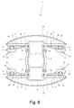
- FIG. 5 shows a schematic representation of a cross section through a further embodiment of a support post according to the invention 1.
- This support post differs from that in FIG. 1 shown support posts 1 characterized in that on opposite sides of the stiffening profile 8, the same assembly is arranged so that from this support post 1 on both sides wall elements 30 can be maintained.
- FIG. 6 shows a schematic representation of a cross section through a further embodiment of a support post according to the invention 1.
- This support post 1 differs from the in FIG. 5 shown support posts 1 characterized in that the legs 2 and 3 are each connected to a cover 37, wherein the cover 37 are fixed by a latching mechanism on the legs 2 and 3 respectively.
- the cover 37 are fixed by a latching mechanism on the legs 2 and 3 respectively.
- FIG. 6 are in FIG. 6 not all reference numerals shown in Figure 5.
- Figure 7a shows a schematic representation of a horizontal section through a further embodiment of a wall 28 according to the invention in the form of a flood protection wall.
- the support post 1 differs from the in FIG. 1 shown supporting posts 1, that it has a securable locking unit 38, with which the separate profile 9 and the edge portion 31 of the wall element 30 on the leg 2 can be locked.
- a bore 39 is arranged on the leg 2, the separate profile 9 and the sealing element 4, through which the locking unit 38 is guided.
- FIG. 7b shows a schematic representation of a horizontal section through a further embodiment of a wall 28 according to the invention in the form of a flood protection wall.
- the locking unit 38 is formed as a continuous bolt passing through the holes 39 in the separate profiles 9 and 10 and the sealing elements 4 and 5 and by a formed on the wall element 30 bore 40 extends.
- the locking unit 38 has at one end a widening 52 and at the other end a bolt portion 53 with a transverse bore 54. At the transverse bore 54, a lock, not shown, can be arranged to secure the position of the locking unit 38 shown.
- FIG. 7c shows a schematic representation of a horizontal section through a further embodiment of a wall 28 according to the invention in the form of a flood protection wall.
- the wall 28 comprises a locking device 41, which has a bolt 42 displaceably mounted on the wall element 30 and a bow-shaped bolt receptacle 43 arranged on the leg 3 of the support post 1.
- the locking device 41 comprises a mounting unit 44, on whose side facing away from the wall element 30 a metallic plate 45 is arranged, on which in turn two brackets 46 and 47 are arranged, on which the bolt 42 is guided.
- the bracket 47 and the bolt 42 each have an angled portion 48 and 49, respectively, on each of which a bore 50 and 51 is formed, on which a not shown lock can be arranged to secure the locking position shown the locking device 41.
- FIG. 8 shows a schematic side view of the in FIG. 7 It can be seen that the locking unit 38 engages an upper end portion of the wall element 30 of the wall 28. In the case of a wall 28 having a plurality of superimposed wall elements 30, the locking unit 38 preferably engages on the uppermost wall element 30.
- FIG. 9a shows a cross section through an embodiment of an inventive, preferably mobile but in some cases also stationary usable wall module 102 or fence module 102 in not assembled state.
- Each wall module 102 or fence module 102 of FIG FIG. 2 shown wall 28 and the in FIG. 2 shown fence 28 is corresponding FIG. 9a formed, which means that the wall modules 102 and fence modules 102 are the same.
- a spring 115 is disposed on one end side and a groove 116 on an opposite end side, the spring 115 and the groove 116 being complementary to one another.
- the wall modules 102 and fence modules 102 can be connected together to form a tongue and groove connection, so that a mobile flood protection wall, fence or wall-fence combination can be established
- the wall module 102 or fence module 102 is modularly constructed from two sub-modules 121 and 122, which are sealed against one another and are positively and non-positively connected to each other, which in FIG. 9a are shown separated from each other and in FIG. 9b are shown joined together.
- the sub-modules 121 and 122 are designed such that they can be connected to one another via a clip connection 128 and a screw connection in a form-fitting and non-positive manner.
- latching projections 129 are arranged on the submodule 121 and latching recesses 130 are arranged on the submodule 122 along in each case one end face of the submodules 121, 122.
- the latching projections 129 of the sub-module 121 are concave or semi-hollow cylindrical on the side facing each other and together with two on the profile of the sub-mode 122 in the recesses 130 arranged projections 132, which on the opposite side concave or semi-circular.
- hollow cylindrical are formed a screw channel which is adapted to a screw, a pin or the like Receive funds, whereby the respective locking projection 129 braced against its release direction and / or can be secured.
- the individual modules 102 which are permanently assembled from the sub-modules 121 and 122, are then as in FIG. 9b presented juxtaposed, wherein the spring 115 of a module 102 engages in the groove 116 of another module 102.
- FIG. 1 indicated bracing 114 the individual modules 102 are then pressed against each other in the case of the preferably mobile (but also stationary in some applications) flood protection wall 28, wherein the secured in the mounting holes 120 by means of fastening protrusion 119 sealing units 118 ensure the tightness of the flood protection wall 28.
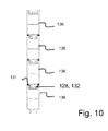
- FIG. 10 shows a preferably stationary, but in some cases also mobile usable (eg, with a crane at the site be moved) embodiment of the flood protection wall 28.
- the wall 28 is here - apart from a floor module 133 formed by a single wall module 102, which consists of a Variety of identically formed sub-modules 136 is joined together. This causes already on the basis of FIG. 9a described Klipstress 128 together with the screw channel formed by the insertion of a screw in the locking projections 129 and the projections 132 a force-shaped, permanent connection of the sub-modules 136, which remains tight due to the inner and protected Untermoduldichtitch 131 for a long time.
- FIG. 11a shows an embodiment of a floor module 133 of the flood protection wall 28 according to the invention in a preferably stationary, but in some cases also mobile usable expression.
- the bottom seal 134 is fixed in a floor module 133 and in this case is clamped and sealed with the aid of screws as a fixing means 135 with a floor rail 117 located in the floor.
- the Upwardly aligned locking recesses of the floor module 133 allow a firm connection with the latching projections 129 of the sub-modules 122.
- FIG. 11b shows a further embodiment of a floor module 133 of the high water protection wall 28 according to the invention in a preferably mobile, but in some cases also stationary usable expression.
- a spring which can engage in the groove 116 of a further wall module 102.
- FIG. 11c represents a further variant of the floor module 133 in a mobile, but in some cases also stationary usable expression.
- the difference from in FIG. 11b described embodiment is that no screwing of the basic module with fixing means 135 and no bottom rail 117 are necessary.
- the tensioner 114 described above is used.
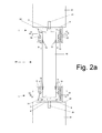
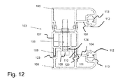
- FIG. 12 shows a cross-section through an embodiment of a support post 103 according to the invention.
- the support post 103 has arranged parallel to each other and spaced apart legs 104, between which for installation of the wall 28 and the fence 28, an edge portion of each wall element 102 and fence element 102 can be.
- the support post 103 has an adjusting device 106 which is formed and connected to the legs 104, that with her the distance of the legs 104 from each other for clamping the arranged between the legs 104 edge portions of the wall modules 2 and fence modules 102 between the legs 104 variable is.
- the support post 103 comprises a base unit 107 which extends in the longitudinal direction of the support post 103 and on which a leg 104 is arranged so as to be non-destructively detachable, wherein the distance from at least one leg 104 to the base unit 107 can be varied by means of the actuation device 6.
- the other leg is connected to the base unit 107.
- This connection can i.a. e.g. by riveting, screwing, welding, etc. done. Shown here is a riveted joint.
- the adjusting device 106 has at least one screw mechanism with a screw 108.
- the screw 8 extends through the base unit 107 and is mounted on the non-detachable leg 104.
- a seal 124 is disposed between the base unit 107 and the profile 105 of the slidable leg 104.
- Each support post 103 further comprises two guide means 109, which are designed and arranged such that with them the leg 104 to be displaced, the distance of which is variable to the base unit 107, is forcibly guided during a movement relative to the base unit 107.
- each guide device 109 has two webs 110 arranged on the base unit 107 and two receptacles 111 arranged on the respective profile 5. Between the webs 110 and the receptacles 111, a respective seal 123 is arranged.
- each leg 104 On the mutually facing sides of the legs 104 each extending over the length of the legs 104 seal 112 is arranged. On each leg 4, a receptacle 13 for holding the respective seal 112 is arranged.
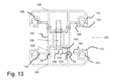
- FIG. 13 shows a further embodiment of the support post 103 according to the invention.
- the support post 103 shown here has two pairs of legs 104, which are adapted to clamp on both sides of the base unit in each case a wall module 102.
- One such post 103 thus serves to extend the flood protection wall 101 and usually has no device for attachment of the support post 103 to a masonry or the like.
- the support post is after FIG. 12 or 13 characterized by at least one extending in the longitudinal direction of the support post 113 base unit 117 to which the legs 114 are arranged non-destructively detachable, wherein the distance from at least one leg 114 to the base unit 117 by means of the adjusting device 116 is variable by at least one (here several Guiding devices (9), are designed and arranged such that with her at least one leg 114 whose distance is variable to the base unit 117, while a movement of this leg 114 is forced relative to the base unit 117.
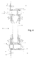
- Figure 14a represents a first example, like the one in FIG. 12 disclosed support post 103 can be connected to the masonry 126 of a gate entrance.
- the profile 105 is anchored over the extension of the profile 105a, in which there is a bore, by means of a screw 127 in the masonry.
- a seal 125 is provided between the masonry 126 and the disclosed support post 103, here consisting of profiles 105, base unit 107 and profile extension 105a which is intended to prevent the water between the masonry 126 and the support post 103 can pass unhindered.
- FIG. 14b shows a further embodiment of the support post 103 after FIG. 12 and the associated possibilities to anchor the support post 103 via fasteners 127 in the masonry.
Landscapes
- Engineering & Computer Science (AREA)
- Architecture (AREA)
- Structural Engineering (AREA)
- Civil Engineering (AREA)
- General Engineering & Computer Science (AREA)
- Environmental & Geological Engineering (AREA)
- Ocean & Marine Engineering (AREA)
- Mechanical Engineering (AREA)
- Business, Economics & Management (AREA)
- Emergency Management (AREA)
- Fencing (AREA)
Abstract
Die Erfindung betrifft einen Stützpfosten (1) für eine Wand (28), insbesondere Hochwasserschutzwand, aufweisend wenigstens zwei parallel zueinander und beabstandet voneinander angeordnete Schenkel (2, 3), zwischen denen zur Aufstellung der Wand (28) ein Randabschnitt (31, 32) von zumindest einem Wandelement (30) anordbar ist, und wenigstens ein parallel zur Längserstreckung des Stützpfostens (1) verlaufend zwischen einem Schenkel (2, 3) und dem Randabschnitt (31, 32) des Wandelementes (30) anordbares Dichtelement (4, 5), gekennzeichnet durch wenigs-tens ein parallel zur Längserstreckung des Stützpfostens (1) verlaufend zwischen dem Schenkel (2, 3) und dem Randabschnitt (31, 32) des Wandelementes (30) anordbares separates Profil (9, 10), an dessen dem Schenkel (2, 3) abgewandter Seite das Dichtelement (4, 5) angeordnet ist, wobei die aus dem Dichtelement (4, 5) und dem separaten Profil (9, 10) gebildete Baugruppe (11, 12) derart ausgebildet ist, dass sie unter Erzeugung einer auf das Dichtelement (4, 5) einwirkenden Klemmkraft quer zur Längserstreckung des Stützpfostens (1) zwischen den Schenkel (2, 3) und den Randabschnitt (31, 32) des Wandelementes (30) einführbar ist.The invention relates to a support post (1) for a wall (28), in particular flood protection wall, comprising at least two legs (2, 3) arranged parallel to one another and at a distance from one another, between which an edge section (31, 32) for erecting the wall (28). at least one wall element (30) can be arranged, and at least one sealing element (4, 5), which can be arranged parallel to the longitudinal extension of the support post (1), extending between a limb (2, 3) and the edge section (31, 32) of the wall element (30). , characterized by at least one parallel to the longitudinal extension of the support post (1) extending between the leg (2, 3) and the edge portion (31, 32) of the wall element (30) arrangeable separate profile (9, 10), on whose leg (2, 3) side facing away from the sealing element (4, 5) is arranged, wherein the assembly of the sealing element (4, 5) and the separate profile (9, 10) formed (11, 12) is formed such that they under Generation of one the sealing element (4, 5) acting clamping force transversely to the longitudinal extent of the support post (1) between the legs (2, 3) and the edge portion (31, 32) of the wall element (30) can be inserted.
Description
Die Erfindung betrifft einen Stützpfosten für eine Wand, insbesondere Hochwasserschutzwand, oder einen Zaun, aufweisend wenigstens zwei parallel zueinander und beabstandet voneinander angeordnete Schenkel, zwischen denen zur Aufstellung der Wand bzw. des Zauns ein Randabschnitt von zumindest einem Wandelement bzw. einem Zaunelement anordbar ist.The invention relates to a support post for a wall, in particular flood protection wall, or a fence having at least two mutually parallel and spaced apart legs between which an edge portion of at least one wall element or a fence element can be arranged to set up the wall or fence.
Des Weiteren betrifft die Erfindung eine Wand, insbesondere Hochwasserschutzwand, oder einen Zaun bzw. eine Hochwasserschutzwand-Zaun-Kombination, aufweisend wenigstens zwei gegeneinander abgedichtet und formschlüssig miteinander verbindbare Wandmodule bzw. Zaunmodule und zumindest zwei Stützpfosten, an denen die Wandmodule bzw. Zaunmodule zur Aufstellung der Wand bzw. des Zauns anordbar sind, wobei an einem Wandmodul bzw. Zaunmodul eine Feder oder ein Vorsprung und an dem anderen Wandmodul bzw. Zaunmodul eine komplementär zu der Feder ausgebildete Nut oder Aussparung angeordnet ist, wodurch die Wandmodule bzw. Zaunmodule miteinander verbindbar sind.Furthermore, the invention relates to a wall, in particular flood protection wall, or a fence or a flood protection wall-fence combination, comprising at least two mutually sealed and positively connectable wall modules or fence modules and at least two support posts on which the wall modules or fence modules for installation the wall or the fence can be arranged, wherein on a wall module or fence module, a spring or a projection and on the other wall module or fence module is formed a complementary to the tongue groove or recess, whereby the wall modules or fence modules are connected to each other ,
Ferner betrifft die Erfindung eine Wand, insbesondere Hochwasserschutzwand, oder einen Zaun, aufweisend wenigstens zwei gegeneinander abgedichtete miteinander verbindbare Wandmodule bzw. Zaunmodule und zumindest zwei Stützpfosten, an denen die Wandmodule bzw. Zaunmodule zur Aufstellung der Wand bzw. des Zauns anordbar sind.Furthermore, the invention relates to a wall, in particular flood protection wall, or a fence, comprising at least two mutually sealed interconnected wall modules or fence modules and at least two support posts on which the wall modules or fence modules for installation of the wall or the fence can be arranged.
Aus der Gebrauchsmusterschrift
Hochwasserschutzwände sind in verschiedenen Ausführungsformen bekannt. Eine solche Hochwasserschutzwand kann mehrere Stützpfosten aufweisen, welche seitlich mit U-förmig ausgebildeten Aufnahmen versehen sind, in die Randabschnitte von Wandelementen eingeführt werden können. An den Stützpfosten sind üblicherweise Dichtungen angeordnet, welche zum Abdichten einer solchen Hochwasserschutzwand mit den in die Aufnahmen eingeführten Randabschnitten der Wandelemente zusammenwirken.Flood protection walls are known in various embodiments. Such a flood protection wall may have a plurality of support posts, which are laterally provided with U-shaped receptacles can be inserted into the edge portions of wall elements. At the support posts usually seals are arranged, which cooperate for sealing such a flood protection wall with the imported into the receptacles edge portions of the wall elements.
Bei der Aufstellung einer entsprechenden Hochwasserschutzwand werden die Wandelemente von oben zwischen zwei benachbart zueinander angeordnete Stützpfosten eingeführt, wodurch die Randabschnitte in die Aufnahmen an den Stützpfosten eingeführt werden. Bei diesem Einführen eines Wandelementes zwischen zwei Pfosten kommt das Wandelement nahezu zwangsläufig mit den Dichtungen in Kontakt, wodurch die Dichtungen beschädigt werden können, was wiederum zu Undichtigkeiten an einer entsprechend ausgebildeten Hochwasserschutzwand führt. Dieses Problem tritt insbesondere bei der Einführung von relativ großen Wandelementen, beispielsweise mit Hilfe eines Krans, zwischen zwei Stützpfosten auf.When installing a corresponding flood protection wall, the wall elements are inserted from above between two mutually adjacent support posts, whereby the edge portions are inserted into the receptacles on the support post. In this insertion of a wall element between two posts, the wall element comes almost inevitably in contact with the seals, whereby the seals can be damaged, which in turn leads to leaks in a suitably trained flood protection wall. This problem occurs in particular in the introduction of relatively large wall elements, for example by means of a crane, between two support posts.
Aufgabe der Erfindung ist es, eine sowohl stationär als auch mobil einsetzbare Wand bzw. einen sowohl stationär als auch mobil einsetzbaren Zaun bzw. Zaun-Wand-Kombination bereitzustellen, welche bzw. welcher in seiner Formgebung auf einfache Art und Weise veränderbar ist und gleichzeitig als höchst zuverlässiger Hochwasserschutz einsetzbar ist. Aufgabe der Erfindung ist es auch, eine Möglichkeit zur zuverlässigen und dauerhaften Abdichtung von Wänden, insbesondere Hochwasserschutzwänden, zu schaffen.The object of the invention is to provide both a stationary and mobile deployable wall or a both stationary and mobile deployable fence or fence-wall combination, which or in its shape in a simple manner can be changed and at the same time as highly reliable flood protection can be used. The object of the invention is also to provide a way for reliable and permanent sealing of walls, especially flood walls.
Diese Aufgabe wird durch einen Stützpfosten gemäß Anspruch 1, eine Wand gemäß Anspruch 10 und eine Wandmodul gemäß Anspruch 16 gelöst. Vorteilhafte Ausgestaltungen sind in den Unteransprüchen angegeben, welche jeweils für sich genommen oder in verschiedener Kombination miteinander einen Aspekt der Erfindung darstellen können.This object is achieved by a support post according to
Mit Anspruch 1 wird ein Stützpfosten für eine Wand, insbesondere Hochwasserschutzwand, vorgeschlagen, aufweisend wenigstens zwei parallel zueinander und beabstandet voneinander angeordnete Schenkel, zwischen denen zur Aufstellung der Wand ein Randabschnitt von zumindest einem Wandelement anordbar ist, und wenigstens ein parallel zur Längserstreckung des Stützpfostens verlaufend zwischen einem Schenkel und dem Randabschnitt des Wandelementes im Anwendungsfall angeordnetes Dichtelement, gekennzeichnet durch wenigstens ein parallel zur Längserstreckung des Stützpfostens verlaufend zwischen dem Schenkel und dem Randabschnitt des Wandelementes im Anwendungsfall angeordnetes separates Profil, an dessen dem Schenkel abgewandter Seite das Dichtelement angeordnet ist, wobei die aus dem Dichtelement und dem separaten Profil gebildete Baugruppe derart ausgebildet ist, dass sie unter Erzeugung einer auf das Dichtelement einwirkenden Klemmkraft quer zur Längserstreckung des Stützpfostens zwischen den Schenkel und den Randabschnitt des Wandelementes im Anwendungsfall eingeführt ist.With
Erfindungsgemäß ist das Dichtelement nicht an einem Schenkel, sondern an einem separat ausgebildeten Profil angeordnet und kann somit nach einer Einführung eines Randabschnitts eines Wandelementes zwischen die beiden Schenkel des Stützpfostens zwischen dem jeweiligen Schenkel und dem Randabschnitt angeordnet werden. Folglich kann es bei der Einführung des Randabschnitts zwischen die beiden Schenkel nicht zu einem Kontakt zwischen Randabschnitt und Dichtelement kommen, so dass eine hierdurch bedingte Beschädigung des Dichtelementes, wie sie aus dem Stand der Technik bekannt ist, nicht auftreten kann. Somit kann mittels des erfindungsgemäßen Stützpfostens eine Wand, insbesondere Hochwasserschutzwand, geschaffen werden, die zuverlässig und dauerhaft abgedichtet ist.According to the invention the sealing element is not arranged on a leg, but on a separately formed profile and can thus be arranged after insertion of an edge portion of a wall element between the two legs of the support post between the respective leg and the edge portion. Consequently, it can not come to a contact between the edge portion and sealing element in the introduction of the edge portion between the two legs, so that a resulting damage to the sealing element, as is known from the prior art, can not occur. Thus, by means of the support post according to the invention a wall, in particular flood protection wall, created, which is reliably and permanently sealed.
Der Stützpfosten kann im Rahmen der Erfindung auch zwei oder mehrere Paare von parallel zueinander und beabstandet voneinander angeordneten Schenkeln aufweisen, zwischen denen zur Aufstellung der Wand jeweils ein Randabschnitt von zumindest einem Wandelement anordbar ist. Auch kann zwischen jedem Schenkel und einem Randabschnitt eines Wandelementes ein parallel zur Längserstreckung des Stützpfostens verlaufend anordbares Dichtelement vorhanden sein.In the context of the invention, the support post can also have two or more pairs of legs arranged parallel to one another and at a distance from one another, between which an edge section of at least one wall element can be arranged for erecting the wall. Also, between each leg and an edge portion of a wall element, a parallel to the longitudinal extent of the support post can be arranged extending sealing element.
Des Weiteren kann der Stützpfosten auch zwei oder mehrere parallel zur Längserstreckung des Stützpfostens verlaufend zwischen einem Schenkel und einem Randabschnitt des Wandelementes im Anwendungsfall angeordnete separate Profile aufweisen, an deren jeweilig einem Schenkel abgewandter Seite jeweils ein Dichtelement angeordnet ist.Furthermore, the support post may also have two or more parallel to the longitudinal extent of the support post extending between a leg and an edge portion of the wall element in the case of use arranged separate profiles, on whose respective side facing away from a leg each have a sealing element is arranged.
Vorzugsweise erstrecken sich das Dichtelement und das separate Profil über die gesamte Länge des jeweiligen Schenkels. Das Dichtelement kann aus einem Elastomer, insbesondere aus Gummi, gebildet sein.Preferably, the sealing element and the separate profile extend over the entire length of the respective leg. The sealing element may be formed of an elastomer, in particular of rubber.
An dem separaten Profil kann eine Aufnahme zur Fixierung des Dichtelementes relativ zu dem separaten Profil angeordnet sein, in der ein Teil des Dichtelementes formschlüssig eingreift. Vorzugsweise ist das Dichtelement austauschbar an der Aufnahme angeordnet, so dass durch die jeweilige Wahl der Art des Dichtelementes der Stützpfosten an die jeweiligen Gegebenheiten anpassbar ist und im Fall eines beschädigten Dichtelementes ein einfacher und schneller Austausch gegen ein neues Dichtelement erfolgen kann.On the separate profile, a receptacle for fixing the sealing element can be arranged relative to the separate profile in which a part of the sealing element engages positively. Preferably, the sealing element is arranged interchangeably on the receptacle, so that by the respective choice of the type of sealing element of the support post can be adapted to the particular circumstances and in the case of a damaged sealing element a simple and quick replacement can be done against a new sealing element.
Durch die Erzeugung einer auf das Dichtelement einwirkenden Klemmkraft wird die Abdichtung einer entsprechend ausgebildeten Wand, insbesondere Hochwasserschutzwand, deutlich verbessert.By generating a clamping force acting on the sealing element, the sealing of a correspondingly formed wall, in particular flood protection wall, is significantly improved.
Gemäß einer vorteilhaften Ausgestaltung weist der Stützpfosten wenigstens eine Klemmeinrichtung mit zumindest einem Klemmglied auf, die derart ausgebildet ist, dass ein Teil des zwischen dem Schenkel und dem Randabschnitt des Wandelementes eingeführten separaten Profils zwischen dem Klemmglied und dem Schenkel einklemmbar ist. Hierdurch kann das separate Profil, und mit ihm das daran angeordnete Dichtelement, an dem übrigen Stützpfosten in seiner bestimmungsgemäßen Stellung fixiert werden. Dies geht mit einer dauerhaften und zuverlässigen Abdichtung einer entsprechend ausgestatteten Wand, insbesondere Hochwasserschutzwand, einher.According to an advantageous embodiment, the support post has at least one clamping device with at least one clamping member, which is designed such that a part of the introduced between the leg and the edge portion of the wall element separate profile between the clamping member and the leg can be clamped. In this way, the separate profile, and with it the sealing element arranged thereon, can be fixed to the rest of the support post in its intended position. This is accompanied by a permanent and reliable sealing of a correspondingly equipped wall, in particular flood protection wall.
Vorteilhafterweise weist das Klemmglied einen freien Endabschnitt und einen mit dem separaten Profil oder mit einem die beiden Schenkel miteinander verbindenden Steg verbundenen Endabschnitt auf, wobei das Klemmglied derart ausgebildet ist, dass zumindest ein Teil des freien Endabschnitts bei zwischen dem Schenkel und dem Randabschnitt des Wandelementes eingeführten separaten Profils in körperlichem Kontakt mit einem an dem separaten Profil ausgebildeten Klemmabschnitt steht, wodurch der freie Endabschnitt über den Klemmabschnitt in Richtung des Schenkels mit einer Klemmkraft beaufschlagt wird. Hierdurch wird bei der Anordnung des separaten Profils zwangsläufig eine Klemmkraft erzeugt, welche über das Klemmglied auf das von der Klemmeinrichtung eingeklemmte Teil des separaten Profils übertragen werden kann. An dem freien Endabschnitt des Klemmglieds und dem Klemmabschnitt des separaten Profils können Abschrägungen zur Begünstigung des Zusammenwirkens von Klemmglied und Klemmabschnitt angeordnet sein. Vorzugsweise ist der freie Endabschnitt des Klemmglieds als von dem Schenkel weg gerichtete Abwinklung ausgebildet. Dies stelle eine optimale Ausgestaltung zur Erzeugung der auf das Klemmglied bzw. den Teil des separaten Profils einwirkenden Klemmkraft dar. Alternativ kann das Klemmglied abgerundet oder dergleichen ausgebildet sein.Advantageously, the clamping member has a free end portion and an end portion connected to the separate profile or web connecting the two legs, the clamping member being formed such that at least a portion of the free end portion is inserted between the leg and the edge portion of the wall member separate profile is in physical contact with a formed on the separate profile clamping portion, whereby the free end portion is acted upon by the clamping portion in the direction of the leg with a clamping force. As a result, a clamping force is necessarily generated in the arrangement of the separate profile, which can be transmitted via the clamping member on the clamped by the clamping member of the separate profile. At the free end portion of the clamping member and the clamping portion of the separate profile chamfers may be arranged to promote the interaction of the clamping member and clamping portion. Preferably, the free end portion of the clamping member is formed as directed away from the leg bend. This represents an optimum embodiment for generating the clamping force acting on the clamping member or the part of the separate profile. Alternatively, the clamping member may be rounded or the like formed.
Nach einer weiteren vorteilhaften Ausgestaltung ist zwischen dem mit dem separaten Profil bzw. dem Steg verbundenen Endabschnitt und dem Schenkel eine Aufnahme ausgebildet, in die der Teil des separaten Profils einführbar ist, wobei an der dem Schenkel abgewandten Seite des freien Endes des zwischen dem Klemmglied und dem Schenkel einklemmbaren Teils des separaten Profils eine Abschrägung angeordnet ist. Mittels der Abschrägung wird die Einführung des Teils des separaten Profils in die Aufnahme erleichtert. Die Abschrägung kann als Fase, Abrundung oder dergleichen ausgebildet sein.According to a further advantageous embodiment, a receptacle is formed between the connected to the separate profile or the web end portion and the leg into which the part of the separate profile is inserted, wherein on the side facing away from the leg of the free end of the between the clamping member and the leg can be clamped part of the separate profile is arranged a chamfer. The bevel facilitates the introduction of the part of the separate profile into the receptacle. The chamfer may be formed as a chamfer, rounding or the like.
Eine weitere vorteilhafte Ausgestaltung sieht vor, dass an der dem separaten Profil abgewandten Seite des Dichtelementes wenigstens eine Dichtlippe angeordnet ist. Hierdurch wird die Dichtwirkung des Dichtelementes erhöht. An der dem separaten Profil abgewandten Seite des Dichtelementes können auch zwei oder mehrere Dichtlippen angeordnet sein.A further advantageous embodiment provides that at least one sealing lip is arranged on the side of the sealing element facing away from the separate profile. As a result, the sealing effect of the sealing element is increased. On the side facing away from the separate profile side of the sealing element and two or more sealing lips may be arranged.
Gemäß einer weiteren vorteilhaften Ausgestaltung weist der Stützpfosten wenigstens ein parallel und beabstandet zur Längserstreckung des Stützpfostens anordbares, mit den Schenkeln verbindbares Versteifungsprofil auf. Dieses Versteifungsprofil kann dem Stützpfosten hohe Steifigkeitseigenschaften verleihen. Das Versteifungsprofil kann als Hohlprofil und/oder im Querschnitt wabenförmig ausgebildet sein.According to a further advantageous embodiment, the support post on at least one parallel and spaced from the longitudinal extension of the support post can be arranged, connectable with the legs stiffening profile. This stiffening profile can give the support post high rigidity properties. The stiffening profile may be formed as a hollow profile and / or honeycomb in cross-section.
Nach einer weiteren vorteilhaften Ausgestaltung umfasst der Stützpfosten wenigstens ein mit zumindest einem Schenkel und/oder dem Versteifungsprofil verbindbares Abdeckelement. Hierdurch kann der von einer entsprechend ausgebildeten Wand beim Betrachter hervorgerufene optische Eindruck verbessert werden, indem der Wand eine ästhetischere Anmutung verliehen wird.According to a further advantageous embodiment, the support post comprises at least one connectable with at least one leg and / or the stiffening profile cover. This can be from a appropriately formed wall in the viewer caused visual impression can be improved by the wall is given a more aesthetic appearance.
Ferner wird es als vorteilhaft erachtet, wenn der Stützpfosten wenigstens eine sicherbare Verriegelungseinheit aufweist, mit der das separate Profil und der Randabschnitt des Wandelementes an wenigstens einem Schenkel arretierbar sind. Hierdurch kann eine Diebstahlsicherung ausgebildet werden, da das separate Profil bei gesicherter Verriegelungseinrichtung nicht dem übrigen Stützprofil entnommen werden kann. Dies ist insbesondere bei separaten Profilen aus Metall von Vorteil, da einem aus anderen Bereichen bekanntem Metalldiebstahl vorgebeugt werden kann. Die sicherbare Verriegelungseinheit kann ein Zylinderschloss, einen Druckzylinder, ein Einsteckschloss, einen Bolzen mit Vorhängeschutz oder dergleichen aufweisen. Eine entsprechende Verriegelungseinrichtung kann auch bei andersartig modular aufgebauten Stützpfosten eingesetzt werden, um eine entsprechende Diebstahlsicherung auszubilden. Des Weiteren kann durch die Anordnung von entsprechenden Verriegelungseinheiten an Wänden in Form von Hochwasserschutzwänden ein Einbruchschutz für Häuser und Gebäude ausgebildet werden, wenn mittels einer solchen Wand eine Tür- Tor-, oder Fensteröffnung in einer Wand eines Hauses bzw. Gebäudes verschlossen wird. Unbefugten Personen ist es durch die mit den Verriegelungseinheiten bewirkten Arretierungen der Komponenten der Hochwasserschutzwand nicht möglich, eine entsprechende Wand wieder zu zerlegen und so Zugang zu einem Haus oder Gebäude zu bekommen. Dies ist von Vorteil, da es bei einer Hochwasser-Gefährdung in der Regel zu einer Evakuierung von Häusern und Gebäuden kommt. Hierdurch könnten unbefugte Personen einen ungehinderten Zugang zu leerstehenden Häusern und Gebäuden bekommen, was jedoch mit den erfindungsgemäßen Stützpfosten bzw. einer damit ausgestatteten Hochwasserschutzwand zuverlässig verhindert werden kann.Furthermore, it is considered advantageous if the support post has at least one securable locking unit, with which the separate profile and the edge portion of the wall element can be locked to at least one leg. In this way, an anti-theft device can be formed, since the separate profile can not be removed from the rest of the support profile when the locking device is secured. This is particularly advantageous for separate profiles made of metal, as can be prevented from other areas known metal theft. The lockable locking unit may include a cylinder lock, a pressure cylinder, a mortise lock, a bolt with padlock or the like. A corresponding locking device can also be used in otherwise modularly constructed support post to form a corresponding anti-theft device. Furthermore, by the arrangement of corresponding locking units on walls in the form of flood walls a burglary protection for houses and buildings are formed when a door gate, or window opening in a wall of a house or building is closed by such a wall. It is not possible for unauthorized persons, due to the locking units of the components of the flood protection wall, to dismantle a corresponding wall and thus gain access to a house or building. This is an advantage as it usually comes with a flood hazard to evacuation of houses and buildings. As a result, unauthorized persons could get unhindered access to empty houses and buildings, but this can be reliably prevented with the support post according to the invention or a flood protection wall equipped therewith.
Ein auch selbständig erfinderischer Stützpfosten für eine Wand, insbesondere Hochwasserschutzwand, oder einen Zaun wird an dieser Stelle vorgeschlagen. Dieser kann auch die erfindungsgemäßen Merkmale aufweisen, aber auch lediglich wenigstens zwei parallel zueinander und beabstandet voneinander angeordnete Schenkel aufweisen, zwischen denen zur Aufstellung der Wand bzw. des Zauns ein Randabschnitt von zumindest einem Wandelement bzw. einem Zaunelement anordbar ist, und welcher wenigstens eine Stelleinrichtung umfasst, die derart ausgebildet und mit den Schenkeln verbunden ist, dass mit ihr der Abstand der Schenkel voneinander zum Einklemmen des zwischen den Schenkeln angeordneten Randabschnitts zwischen den Schenkeln variierbar ist. Herkömmliche Stützpfosten, welche eine Stelleinrichtung zur Variierung des Abstandes der Schenkel besitzen funktionieren meist nur, wenn beidseitig Randabschnitte eines Wandelementes oder Zaunelementes angeordnet werden. Der hier vorgeschlagene auch selbständig erfinderische Stützpfosten kann auch lediglich zwei Schenkel besitzen und dennoch ein sicheres Abdichten zwischen dem Stützpfosten und dem Wandelement bzw. Zaunelement ermöglichen, denn er weist neben der Stelleinrichtung wenigstens eine Führungseinrichtung auf, die derart ausgebildet und angeordnet ist, dass mit ihr der wenigstens eine Schenkel, dessen Abstand zu der Basiseinheit variierbar ist, während einer Bewegung dieses Schenkels relativ zu der Basiseinheit zwangsgeführt wird. Dies sichert die Aufbringung einer gewünschten Klemmkraft bei einer Variation des Abstandes der Schenkel voneinander, insbesondere da durch die Zwangsführung ein die jeweilige Klemmkraft verringerndes Verkanten des Schenkels verhindert wird. Mittels des Stellmechanismus können auch beide Schenkel relativ zu der Basiseinheit verstellt werden. Der Stützpfosten kann für jeden Schenkel eine eigene Führungseinrichtung oder für zwei oder mehrere Schenkel eine gemeinsame Führungseinrichtung aufweisen. Diese Zwangsführung ist auch Vorteilhaft bei zwei paarweisen Schenkeln des Stützpfostens. Insbesondere, wenn zwischen zwei Schenkel - obgleich vorhanden - kein Randabschnitt eines Wandelements eingeführt worden ist. In diesem Zusammenhang ist mit Zwangsführung eine Vorrichtung bzw. Merkmal zu verstehen, welches eine zusätzliche Führung neben der Stelleinheit darstellt und ein sicheres Einklemmen eines Randabschnittes auf nur einer Seite des Stützpfostens ermöglicht. Besonders bevorzugt wird die Zwangsführung durch einen Zapfen realisiert, der in eine Aussparung eingreift.A self-inventive inventive support post for a wall, especially flood protection wall, or a fence is proposed at this point. This may also have the features of the invention, but also only at least two mutually parallel and spaced apart legs have, between which for setting up the wall or the fence, an edge portion of at least one wall element or a fence element can be arranged, and which at least one adjusting device comprises, which is formed and connected to the legs, that with her the distance of the legs from each other for clamping the arranged between the legs edge portion between the legs is variable. Conventional support posts, which have an adjusting device for varying the distance between the legs, usually only work if edge sections of a wall element or fence element are arranged on both sides. The proposed here also independently inventive support post can also have only two legs and still allow a secure sealing between the support post and the wall element or fence element, because he has next to the adjusting device at least one guide device which is designed and arranged such that with her the at least one leg whose distance to the base unit is variable, during a movement of this leg is forced relative to the base unit. This ensures the application of a desired clamping force with a variation of the distance of the legs from each other, in particular because the positive guidance of the respective clamping force reducing tilting of the leg is prevented. By means of the adjusting mechanism, both legs can be adjusted relative to the base unit. The support post may have a separate guide device for each leg or a common guide device for two or more legs. This forced operation is also advantageous in two pairs of legs of the support post. In particular, if between two legs - although present - no edge portion of a wall element has been introduced. In this context, positive guidance means a device or feature which constitutes an additional guide next to the setting unit and enables a secure clamping of a rim portion on only one side of the support post. Particularly preferably, the forced operation is realized by a pin which engages in a recess.
Gemäß einer vorteilhaften Ausgestaltung weist die Stelleinrichtung wenigstens einen Schraubmechanismus auf. Dies stellt eine konstruktiv einfache Ausgestaltung des Stellmechanismus dar. Der Stellmechanismus kann auch zwei oder mehrere Schraubmechanismen aufweisen. Über den Schraubmechanismus lässt sich der Abstand der Schenkel voneinander sehr exakt variieren, wobei gleichzeitig eine Erzeugung von ausreichenden Klemmkräften auf einfache Art und Weise ermöglicht wird.According to an advantageous embodiment, the adjusting device has at least one screw mechanism. This represents a structurally simple embodiment of the adjusting mechanism. The adjusting mechanism can also have two or more screw mechanisms. About the screw mechanism, the distance between the legs of each other can vary very accurately, while at the same time a generation of sufficient clamping forces in a simple manner is possible.
Nach einer weiteren vorteilhaften Ausgestaltung ist an einer dem jeweilig anderen Schenkel zugewandten Seite von wenigstens einem Schenkel zumindest eine wenigstens über einen Teil der Länge des Schenkels verlaufende Dichtung angeordnet. Hierdurch kann der mit der Dichtung versehene Schenkel gegenüber einem Wandelement bzw. Zaunelement abgedichtet werden. Auch kann an jedem Schenkel eine entsprechende Dichtung angeordnet sein, um die Dichtheit einer entsprechend ausgebildeten Wand bzw. eines entsprechend ausgebildeten Zauns zu erhöhen. Des Weiteren können an einem Schenkel auch zwei oder mehrere parallel verlaufenden Dichtungen angeordnet sein. Vorzugsweise erstreckt sich die Dichtung über die gesamte Länge des Schenkels. Die Dichtung kann aus einem Elastomer, insbesondere aus Gummi gebildet sein.According to a further advantageous embodiment, at least one of at least one leg, at least over a part of the length of the leg extending seal disposed on a side facing the respective other leg. As a result, the leg provided with the seal can be sealed against a wall element or fence element. Also, a corresponding seal can be arranged on each leg to increase the tightness of a correspondingly formed wall or a correspondingly formed fence. Furthermore, two or more parallel seals may be arranged on one leg. Preferably, the seal extends over the entire length of the leg. The seal may be formed of an elastomer, in particular of rubber.
Vorteilhafterweise ist an wenigstens einem Schenkel zumindest eine Aufnahme zum Halten der Dichtung angeordnet. Die Aufnahme kann eine Fixierung der Dichtung relativ zu dem jeweiligen Schenkel ermöglichen. Vorzugsweise ist die Dichtung austauschbar an der Aufnahme angeordnet, so dass durch die jeweilige Wahl der Art der Dichtung der Stützpfosten an die jeweiligen Gegebenheiten anpassbar ist und im Fall einer beschädigten Dichtung ein einfacher und schneller Austausch gegen eine neue Dichtung erfolgen kann.Advantageously, at least one receptacle for holding the seal is arranged on at least one leg. The receptacle may allow a fixation of the seal relative to the respective leg. Preferably, the seal is arranged interchangeably on the receptacle, so that the respective choice of the type of seal the support post to the particular circumstances is customizable and in the case of a damaged seal a simple and quick replacement can be done against a new seal.
In einer weiteren vorteilhaften Ausführungsform ist vorgesehen, dass der Stützpfosten wenigstens eine sich in Längsrichtung des Stützpfostens erstreckende Basiseinheit aufweist, an der die Schenkel zerstörungsfrei lösbar angeordnet sind, wobei der Abstand von wenigstens einem Schenkel zu der Basiseinheit mittels der Stelleinrichtung variierbar ist. Der Stützpfosten kann zwei entsprechende Paare von Schenkeln aufweisen, wobei zwischen jedem Paar ein Randabschnitt eines Wandelementes bzw. Zaunelementes einklemmbar ist. Wird ein entsprechender Stützpfosten beispielsweise als Endpfosten einer Wand bzw. eines Zauns eingesetzt, kann zur Schaffung einer ästhetischeren Anmutung der Wand bzw. des Zauns das nicht benötigte Paar von Schenkeln zerstörungsfrei von dem Stützpfosten gelöst und von diesem entfernt werden. Der Schraubmechanismus des Stellmechanismus kann teilweise an der Basiseinheit angeordnet und geführt sein. Vorzugsweise sind die Schenkel über jeweils eine Presspassung kraftschlüssig mit der Basiseinheit verbunden oder Teil dieser.In a further advantageous embodiment it is provided that the support post has at least one extending in the longitudinal direction of the support post base unit on which the legs are arranged non-destructively detachable, wherein the distance from at least one leg to the base unit by means of the adjusting device is variable. The support post can have two corresponding pairs of legs, wherein between each pair an edge portion of a wall element or fence element can be clamped. For example, if a corresponding support post is used as the end post of a wall or fence, the unneeded pair of legs can be nondestructively detached from and removed from the support post to create a more aesthetic appearance of the wall or fence. The screw mechanism of the adjusting mechanism may be partially disposed and guided on the base unit. Preferably, the legs are each connected via a press fit frictionally connected to the base unit or part of this.
Durch die erfindungsgemäße Ausgestaltung des Stützpfostens kann folglich eine Wand bzw. ein Zaun als Bausatz bereitgestellt werden, welche bzw. welcher insbesondere auch von einem Verbraucher auf einfache Art und Weise mit einer geeigneten und gewünschten Formgebung aufgestellt, versetzt und in seiner Formgebung verändert werden kann. Die Wand bzw. der Zaun kann stationär eingesetzt und in seiner Formgebung verändert werden. Alternativ kann die Wand bzw. der Zaun mobil eingesetzt werden, insbesondere um eine Hochwasserschutzwand auszubilden, da die Montage der Wand bzw. des Zauns einfach und schnell möglich ist.As a result of the configuration of the support post according to the invention, a wall or a fence can thus be provided as a kit, which can be erected, displaced and shaped in its shape in particular by a consumer in a simple manner with a suitable and desired shape. The wall or the fence can be used stationary and changed in its shape. Alternatively, the wall or the fence can be used mobile, in particular to form a flood protection wall, since the installation of the wall or the fence is easy and fast.
Beispielsweise kann auch mittels erfindungsgemäßer Stützpfosten ein Zaun mit einer gewünschten Formgebung aufgestellt werden, welcher bei Bedarf auf einfache Art und Weise und schnell zu einer Hochwasserschutzwand umgebaut werden kann, und umgekehrt. Eine Änderung der Formgebung einer solchen Wand bzw. eines solchen Zauns kann jedoch auch aus rein ästhetischen Gründen vorgenommen werden. Auch kann die Formgebung einer Wand bzw. eines Zauns unter Verwendung von erfindungsgemäßen Stützpfosten auf einfache Art und Weise an die jeweiligen Anforderungen beispielsweise bezüglich der Undurchlässigkeit für bestimmte Tierarten angepasst werden.For example, a fence with a desired shape can also be set up by means of support posts according to the invention, which can be rebuilt if necessary in a simple manner and quickly to a flood protection wall, and vice versa. However, a change in the shape of such a wall or such a fence can also be made for purely aesthetic reasons. Also, the shape of a wall or a fence using support posts according to the invention can be adapted in a simple manner to the respective requirements, for example with respect to the impermeability to certain species.
Eine weitere vorteilhafte Ausgestaltung für alle Arten der hier beschriebenen Stützpfosten sieht vor, dass der Stützpfosten wenigstens eine Verspanneinrichtung aufweist, die derart ausgebildet und angeordnet ist, dass mit ihr das Wandelement bzw. das Zaunelement mit einer zum Boden gerichteten Kraft beaufschlagbar ist. Hierdurch kann das wenigstens eine Wandelement bzw. Zaunelement gegen den Boden gepresst werden, um beispielsweise eine Hochwasserschutzwand auszubilden, ohne dass Wasser zwischen dem Wandelement bzw. Zaunelement und dem Boden durch die Wand bzw. den Zaun durchtreten kann. Die Verspanneinrichtung kann wenigstens einen zum Verspannen eingerichteten Schraubmechanismus aufweisen.A further advantageous embodiment for all types of support posts described here provides that the support post has at least one bracing device, which is designed and arranged such that with it the wall element or the fence element can be acted upon with a force directed to the ground. As a result, the at least one wall element or fence element can be pressed against the ground in order, for example, to form a flood protection wall, without water being able to pass through the wall or the fence between the wall element or fence element and the floor. The bracing means may comprise at least one screw mechanism arranged for bracing.
Mit Anspruch 10 wird eine Wand, insbesondere Hochwasserschutzwand, oder ein Zaun oder eine Schutzwand-Zaun-Kombination vorgeschlagen, aufweisend wenigstens zwei gegeneinander abgedichtet und formschlüssig miteinander verbindbare Wandmodule bzw. Zaunmodule und zumindest zwei Stützpfosten, an denen die Wandmodule bzw. Zaunmodule zur Aufstellung der Wand bzw. des Zauns anordbar sind, wobei wenigstens ein Modul durch wenigstens zwei Untermodule mit Hilfe einer entlang einer Längsseite der Untermodule angeordneten Klipsverbindung zusammengesetzt ist, und wobei bevorzugt die Untermoduldichtung nach außen nicht sichtbar angeordnet ist.With
Durch die Zusammensetzung eines Moduls durch zwei Untermodule mittels einer Klipsverbindung und mindestens einer innen liegender Dichtung ist es möglich, eine Hochwasserschutzwand, einen Zaun bzw. eine Zaun-Wand-Kombination bereit zu stellen, welche(r) je nach Einsatzgebiet - ob stationär oder mobil - zusammensetzbar ist und durch die innen liegende Dichtung(en) besonders verschleißresistent ist.The composition of a module by two sub-modules by means of a clip connection and at least one inner seal, it is possible to provide a flood protection wall, a fence or a fence-wall combination, which (r) depending on the application - whether stationary or mobile - is composable and is particularly resistant to wear by the inner seal (s).
Durch die Anordnung der Dichtungen sind diese bei zusammengesetzten Wandmodulen bzw. Zaunmodulen unzugänglich angeordnet, so dass es zu keiner Beschädigung der Dichtungen oder zu Verunreinigungen an den Dichtungen kommen kann, welche die Dichtheit der Abdichtung der Wandmodule bzw. Zaunmodule und damit auch der ganzen Wand beeinträchtigen könnten. Auch sind die Dichtungen weniger der Sonnenstrahlung ausgesetzt, die das Dichtungsmaterial spröde werden lässt. Die Klipsverbindung stellt zudem eine einfache Verbindbarkeit der Untermodule dar, insbesondere da zur Verbindung der Untermodule bei einer reinen Klipsverbindung kein Werkzeug verwendet werden muss. Zudem müssen nur relativ klein ausgebildete Untermodule bevorratet werden, um beispielsweise eine Hochwasserschutzwand ausbilden zu können. Des Weiteren kann in gewissem Maße eine geeignete Vormontage von Wandmodulen bzw. Zaunmodulen erfolgen, um beispielsweise eine Hochwasserschutzwand schneller am Einsatzort aufstellen zu können.Due to the arrangement of the seals, these are inaccessible in composite wall modules or fence modules, so that there may be no damage to the seals or contaminants on the seals, which affect the tightness of the sealing of the wall modules or fence modules and thus the entire wall could. Also, the gaskets are less exposed to solar radiation, which makes the gasket material brittle. The clip connection also represents a simple connectivity of the sub-modules, especially since no tool must be used to connect the sub-modules in a pure clip connection. In addition, only relatively small submodules have to be stored in order to be able to form, for example, a flood protection wall. Furthermore, to a certain extent, a suitable pre-assembly of wall modules or fence modules can be made, for example, to be able to set up a flood protection wall faster at the site.
Gemäß einer bevorzugten Ausführungsvariante sind die Untermodule nicht nur formschlüssig über eine Klipsverbindung miteinander verbunden, sondern auch noch kraftschlüssig. Eine kraftschlüssige Verbindung ist bevorzugt dadurch gebildet, dass der entlang einer Längsseite eines Untermoduls angeordnete Rastvorsprung der Klipsverbindung, welcher in eine entlang einer Längsseite eines weiteren Untermoduls angeordnete Rastaussparung eingreift, durch eine Schraube, einen Stift oder durch andere geeignete Mittel gegen die Lösrichtung der Klipsverbindung verspannt ist.According to a preferred embodiment, the sub-modules are not only positively connected to each other via a clip connection, but also still positively. A non-positive connection is preferably formed in that the latching projection of the clip connection arranged along a longitudinal side of a sub-module, which latching recess is arranged in a latching recess arranged along a longitudinal side of a further submodule engages, is braced by a screw, a pin or by any other suitable means against the release direction of the clip connection.
Gemäß einer noch weiter bevorzugten Ausführungsform wird durch den Rastvorsprung und die Rastaussparung der Untermodule ein Schraubenkanal gebildet, welcher durch Einführen einer Schraube geweitet wird, wodurch der Rastvorsprung des Untermoduls entgegen der Lösrichtung der Klipsverbindung verspannt wird.According to a still further preferred embodiment, a screw channel is formed by the latching projection and the latching recess of the sub-modules, which is widened by inserting a screw, whereby the latching projection of the sub-module is braced against the release direction of the clip connection.
Da eine hier beschriebene Kombination aus Klipsverbindung und kraftschlüssiger Verbindung aus dem Stand der Technik nicht bekannt ist, ist ein gegenüber der Hochwasserschutzwand, dem Zaun bzw. der Wand-Zaun-Kombination unabhängiger erfinderischer Aspekt ein Profil, welches wenigsten über eine oben beschriebene Rastaussparung und/oder einen Rastvorsprung für eine Klipsverbindung verfügt, welche(r) so ausgebildet ist, dass beim Zusammenfügen der Klipsverbindung ein Kanal gebildet wird, der zum Einführen einer Schraube, eines Stiftes oder anderer geeigneter Mittel geeignet ist und wodurch der Rastvorsprung des Profils entgegen die Lösrichtung der Klipsverbindung verspannbar ist.Since a combination of clip connection and non-positive connection described here is not known from the prior art, an inventive aspect independent of the flood protection wall, the fence or the wall-fence combination is a profile which has at least one latching recess described above and / or or a snap-in projection for a clip connection, which is designed so that when joining the clip connection, a channel is formed, which is suitable for inserting a screw, a pin or other suitable means and whereby the locking projection of the profile against the loosening of the Clip connection is clamped.
Bei einem bevorzugt stationären Hochwasserschutzsystem ist die Wand gemäß einer Ausführungsform aus Untermodulen aufgebaut, welche sowohl über einen Rastvorsprung, als auch über eine Rastaussparung verfügen. Dementsprechend ist die Wand - abgesehen von einem Bodenprofil und ggf. einem oberen Abschlussprofil - durch ein einziges später untrennbares Modul gebildet, welches aus einer Mehrzahl von Untermodulen zusammengesetzt ist.In a preferably stationary flood protection system, the wall is constructed in accordance with one embodiment of sub-modules, which have both a latching projection, as well as a latching recess. Accordingly, the wall is - apart from a bottom profile and optionally an upper end profile - formed by a single module later inseparable, which is composed of a plurality of sub-modules.
Bei einem bevorzugt mobilen Hochwasserschutzsystem ist bevorzugt ein Modul durch wenigsten zwei Untermodule gebildet, von denen eines entlang einer Stirnseite eine Rastausnehmung aufweist und auf seiner gegenüberliegenden Stirnseite eine Feder oder Nut besitzt, welche dazu ausgebildet ist, in die Feder oder Nut eines weiteren Moduls eingreifen zu können und eine lösbare und dichte Verbindung mit diesem einzugehen. Ein weiteres Untermodul besitzt gleichzeitig einen Rastvorsprung auf einer Stirnseite sowie auf seiner gegenüberliegenden Stirnseite eine Feder oder Nut, welche dazu ausgebildet ist, in die Feder oder Nut eines weiteren Moduls eingreifen zu können und eine lösbare und dichte Verbindung einzugehen.In a preferred mobile flood protection system, a module is preferably formed by at least two sub-modules, one of which has a latching recess along one end face and has a spring or groove on its opposite end face, which has is designed to be able to engage in the spring or groove of another module and to enter into a detachable and sealed connection with this. Another sub-module has at the same time a latching projection on one end face and on its opposite end face a spring or groove which is adapted to engage in the spring or groove of another module and to enter into a detachable and sealed connection.
Die beschriebene Klips- und Schraubverbindung insbesondere für die Verbindung von Profilen kann daher nicht nur besonders vorteilhaft zur Verbindung der Untermodule der Hochwasserschutzwand eingesetzt werden, sondern auch zum Beispiel für Rahmen, Türen, Fenster, Messestände und allen anderen Konstruktionen, wo bevorzugt Profile zur Herstellung eines mechanischen Trägers oder Tragwerks verbunden werden.The Klips and screw connection described in particular for the connection of profiles can therefore be used not only particularly advantageous for connecting the submodules of the flood protection wall, but also, for example, for frames, doors, windows, exhibition stands and all other constructions, where preferably profiles for producing a mechanical support or structure are connected.
Nach einer vorteilhaften Ausgestaltung sind die Wandmodule bzw. Zaunmodule für die mobile Ausführungsvariante der Hochwasserschutzwand gleich ausgebildet, wobei an jedem Wandmodul bzw. Zaunmodul an einer Stirnseite eine Feder und an einer gegenüberliegenden Stirnseite eine Nut angeordnet ist. Dies macht die Herstellung von lediglich einem einheitlichen Wandmodul bzw. Zaunmodul erforderlich, was die Herstellungskosten reduziert. Zudem können auch drei oder mehrere gleich ausgebildete Wandmodule bzw. Zaunmodule zur Aufstellung einer Wand bzw. eines Zauns auf einfache Art und Weise miteinander verbunden werden. Besonders bevorzugt sind die Wandmodule darüber hinaus im Querschnitt symmetrisch aufgebaut. Das hat den Vorteil, dass man bei dem Aufbau eines Zaunes oder einer Hochwasserschutzwand nicht darauf achten muss, welche Seite des Zaunmoduls dem Wasser zugewandt sein soll und welche in die andere Richtung weisen soll.According to an advantageous embodiment, the wall modules or fence modules for the mobile variant of the flood protection wall are the same, wherein on each wall module or fence module on a front side a spring and an opposite end face a groove is arranged. This requires the production of only a single wall module or fence module, which reduces manufacturing costs. In addition, three or more equally trained wall modules or fence modules for setting up a wall or a fence can be connected to each other in a simple manner. Particularly preferably, the wall modules are constructed symmetrically in cross section beyond. This has the advantage that you do not have to pay attention to the construction of a fence or a flood protection wall, which side of the fence module should face the water and which should point in the other direction.
Gemäß einer weiteren vorteilhaften Ausgestaltung ist wenigstens ein Stützpfosten gemäß einer der vorgenannten Ausgestaltungen des Stützpfosten oder einer beliebigen Kombination derselben ausgebildet und bildet zusammen mit den aus Untermodulen zusammengesetzten Modulen eine besonders bevorzugte Ausführungsform der Hochwasserschutzwand, des Zauns bzw. der Wand-Zaun-Kombination. Hiermit sind die oben mit Bezug auf den Stützpfosten genannten Vorteile entsprechend verbunden.According to a further advantageous embodiment, at least one support post according to one of the aforementioned embodiments of the support post or any combination thereof, and forms together with the modules composed of sub-modules a particularly preferred embodiment of the flood protection wall, the fence or the wall-fence combination. Hereby, the advantages mentioned above with respect to the support post are connected accordingly.
Mit Anspruch 15 wird eine Wand, insbesondere Hochwasserschutzwand, oder ein Zaun vorgeschlagen, aufweisend wenigstens zwei gegeneinander abgedichtet miteinander verbindbare Wandmodule bzw. Zaunmodule und zumindest zwei Stützpfosten, an denen die Wandmodule bzw. Zaunmodule zur Aufstellung der Wand bzw. des Zauns anordbar sind, dadurch gekennzeichnet, dass wenigstens ein Stützpfosten gemäß einer der vorgenannten Ausgestaltungen des Stützpfosten oder einer beliebigen Kombination derselben ausgebildet sind. Hiermit sind die oben mit Bezug auf den Stützpfosten genannten Vorteile entsprechend verbunden.With
Die Erfindung betrifft zudem ein Wandmodul, welches aus zwei Untermodulen zusammengesetzt ist, die mit bevorzugt einer Klips- und Schraubverbindung miteinander kraft- und formschlüssig verbunden sind und mindestens eine, vorzugsweise aber zwei innen liegende Dichtung(en) aufweist. Gemäß einer Ausführungsform verfügt das Wandmodul über eine Nut und eine Feder und ist bevorzugt im Querschnitt symmetrisch aufgebaut. Zusätzlich weist das Wandmodul gemäß einer Ausführungsform eine Verspanneinrichtung auf, die es ermöglicht, die Wandmodule gegenüber den Pfosten und/oder gegenüber dem Boden zu verspannen.The invention also relates to a wall module, which is composed of two sub-modules, which are preferably non-positively and positively connected with one another Klips- and screw and having at least one, but preferably two inner seal (s). According to one embodiment, the wall module has a groove and a spring and is preferably constructed symmetrically in cross section. In addition, according to one embodiment, the wall module has a bracing device, which makes it possible to brace the wall modules with respect to the posts and / or with respect to the floor.
Im Folgenden wird die Erfindung unter Bezugnahme auf die anliegenden Figuren anhand von bevorzugten Ausführungsbeispielen exemplarisch erläutert, wobei die nachfolgend dargestellten Merkmale sowohl jeweils für sich genommen als auch in unterschiedlicher Kombination miteinander einen Aspekt der Erfindung darstellen können. Es zeigen
- Figur 1:
- eine schematische Darstellung eines Querschnitts durch ein Ausführungsbeispiel für einen erfindungsgemäßen Stützpfosten,
- Figur 2:
- eine schematische Darstellung eines Horizontalschnitts durch ein Ausführungsbeispiel für eine erfindungsgemäße Wand in Form einer Hochwasserschutzwand,
- Figur 2a:
- eine schematische Darstellung eines Horizontalschnitts durch ein weiteres Ausführungsbeispiel für eine erfindungsgemäße Wand in Form einer Hochwasserschutzwand,
- Figur 3:
- eine schematische Darstellung eines Querschnitts durch ein weiteres Ausführungsbeispiel für einen erfindungsgemäßen Stützpfosten,
- Figur 4:
- eine schematische Darstellung eines Horizontalschnitts durch ein weiteres Ausführungsbeispiel für eine erfindungsgemäße Wand in Form einer Hochwasserschutzwand,
- Figur 5:
- eine schematische Darstellung eines Querschnitts durch ein weiteres Ausführungsbeispiel für einen erfindungsgemäßen Stützpfosten,
- Figur 6:
- eine schematische Darstellung eines Querschnitts durch ein weiteres Ausführungsbeispiel für einen erfindungsgemäßen Stützpfosten,
- Figur 7a:
- eine schematische Darstellung eines Horizontalschnitts durch ein weiteres Ausführungsbeispiel für eine erfindungsgemäße Wand in Form einer Hochwasserschutzwand,
- Figur 7b:
- eine schematische Darstellung eines Horizontalschnitts durch ein weiteres Ausführungsbeispiel für eine erfindungsgemäße Wand in Form einer Hochwasserschutzwand,
- Figur 7c:
- eine schematische Darstellung eines Horizontalschnitts durch ein weiteres Ausführungsbeispiel für eine erfindungsgemäße Wand in Form einer Hochwasserschutzwand, und
- Figur 8:
- eine schematische Seitenansicht der in
Figur 7 - Figur 9a:
- einen Querschnitt durch ein Ausführungsbeispiel für ein erfindungsgemäßes, bevorzugt mobil verwendbares Wandmodul bzw. Zaunmodul im nicht montiertem Zustand,
- Figur 9b:
- einen Querschnitt durch ein Ausführungsbeispiel für ein erfindungsgemäßes, bevorzugt mobil verwendbares Wandmodul bzw. Zaunmodul in montiertem Zustand,
- Figur 10:
- einen Querschnitt durch ein Ausführungsbeispiel für ein erfindungsgemäßes, bevorzugt stationär verwendbares Wandmodul bzw. Zaunmodul im zusammengesetzten Zustand,
- Figur 11a:
- eine erste Ausführungsform eines Bodenabschlussmoduls,
- Figur 11b:
- eine zweite Ausführungsform eines Bodenabschlussmoduls,
- Figur 11c:
- eine dritte Ausführungsform eines Bodenabschlussmoduls,
- Figur 12:
- einen Querschnitt durch ein Ausführungsbeispiel des selbständig erfinderischen Stützpfostens,
- Figur 13:
- eine zweite Ausführungsform des selbständig erfinderischen Stützpfostens,
- Figur 14a:
- eine Draufsicht auf die Wand mit
Stützpfosten nach Figur 12 an einer Toröffnung montiert, - Figur 14b:
- eine Draufsicht auf die Wand mit
Stützpfosten nach Figur 12 auf eine zweite Weise an einer Toröffnung montiert.
- FIG. 1:
- a schematic representation of a cross section through an embodiment of a support post according to the invention,
- FIG. 2:
- 1 is a schematic representation of a horizontal section through an exemplary embodiment of a wall according to the invention in the form of a flood protection wall;
- FIG. 2a:
- a schematic representation of a horizontal section through a further embodiment of a wall according to the invention in the form of a flood protection wall,
- FIG. 3:
- a schematic representation of a cross section through a further embodiment of a support post according to the invention,
- FIG. 4:
- a schematic representation of a horizontal section through a further embodiment of a wall according to the invention in the form of a flood protection wall,
- FIG. 5:
- a schematic representation of a cross section through a further embodiment of a support post according to the invention,
- FIG. 6:
- a schematic representation of a cross section through a further embodiment of a support post according to the invention,
- FIG. 7a:
- a schematic representation of a horizontal section through a further embodiment of a wall according to the invention in the form of a flood protection wall,
- FIG. 7b:
- a schematic representation of a horizontal section through a further embodiment of a wall according to the invention in the form of a flood protection wall,
- FIG. 7c:
- a schematic representation of a horizontal section through a further embodiment of a wall according to the invention in the form of a flood protection wall, and
- FIG. 8:
- a schematic side view of in
FIG. 7 shown wall. - FIG. 9a:
- a cross section through an embodiment of an inventive, preferably mobile usable wall module or fence module in the non-mounted state,
- FIG. 9b:
- a cross section through an embodiment of an inventive, preferably mobile usable wall module or fence module in the assembled state,
- FIG. 10:
- a cross section through an embodiment of an inventive, preferably stationary usable wall module or fence module in the assembled state,
- FIG. 11a:
- a first embodiment of a bottom termination module,
- FIG. 11b:
- a second embodiment of a bottom termination module,
- FIG. 11c:
- a third embodiment of a bottom termination module,
- FIG. 12:
- a cross section through an embodiment of the self-inventive support post,
- FIG. 13:
- a second embodiment of the self-inventive support post,
- FIG. 14a:
- a plan view of the wall with support post to
FIG. 12 mounted on a door opening, - FIG. 14b:
- a plan view of the wall with support post to
FIG. 12 mounted in a second way on a door opening.
Der Stützpfosten 1 weist des Weiteren zwei parallel zur Längserstreckung des Stützpfostens 1 verlaufend jeweils zwischen einem Schenkel 2 bzw. 3 und dem Randabschnitt 31 bzw. 32 des Wandelementes 30 angeordnete separate Profile 9 bzw. 10 auf. An den dem jeweiligen Schenkel 2 bzw. 3 abgewandten Seiten der separaten Profile 9 bzw. 10 ist jeweils eines der Dichtelemente 4 bzw. 5 angeordnet. Die aus einem Dichtelement 4 bzw. 5 und einem separaten Profil 9 bzw. 10 gebildete Baugruppe 11 bzw. 12 ist derart ausgebildet, dass sie unter Erzeugung einer auf das jeweilige Dichtelement 4 bzw. 5 einwirkenden Klemmkraft quer zur Längserstreckung des Stützpfostens 1 zwischen den jeweiligen Schenkel 2 bzw. 3 und den Randabschnitt des Wandelementes eingeführt ist. An der dem jeweiligen separaten Profil 9 bzw. 10 abgewandten Seite des jeweiligen Dichtelementes 4 bzw. 5 sind zwei Dichtlippen 13 angeordnet.The
Der Stützpfosten 1 umfasst zudem zwei Klemmeinrichtungen 14 und 15 mit jeweils einem Klemmglied 16 bzw. 17, die derart ausgebildet sind, dass ein Teil 18 bzw. 19 des jeweilig zwischen dem jeweiligen Schenkel 2 bzw. 3 und dem Randabschnitt 31 bzw. 32 des Wandelementes 30 eingeführten separaten Profils 9 bzw. 10 zwischen dem Klemmglied 16 bzw. 17 und dem Schenkel 2 bzw. 3 einklemmbar ist.The
Jedes Klemmglied 16 bzw. 17 weist einen freien Endabschnitt 20 bzw. 21 und einen mit dem Steg 6 verbundenen Endabschnitt 22 bzw. 23 auf. Jedes Klemmglied 16 bzw. 17 ist derart ausgebildet, dass zumindest ein Teil des jeweiligen freien Endabschnitts 20 bzw. 21 bei zwischen dem jeweiligen Schenkel 2 bzw. 3 und dem Randabschnitt 31 bzw. 32 des Wandelementes 30 jeweilig eingeführten separaten Profils 9 bzw. 10 in körperlichem Kontakt mit einem an dem separaten Profil 9 bzw. 10 ausgebildeten Klemmabschnitt 24 bzw. 25 steht, wodurch der freie Endabschnitt 20 bzw. 21 über den Klemmabschnitt 24 bzw. 25 in Richtung des Schenkels 2 bzw. 3 mit einer Klemmkraft beaufschlagt wird. Der freie Endabschnitt 20 bzw. 21 des jeweiligen Klemmglieds 16 bzw. 17 ist als von dem jeweiligen Schenkel 2 bzw. 3 weg gerichtete Abwinklung ausgebildet.Each clamping
Zwischen dem mit dem Steg 6 verbundenen Endabschnitt 22 bzw. 23 des jeweiligen Klemmglieds 16 bzw. 17 und dem jeweiligen Schenkel 2 bzw. 3 ist jeweils eine Aufnahme ausgebildet ist, in die der Teil 18 bzw. 19 des jeweiligen separaten Profils 9 bzw. 10 eingeführt ist, wobei an der dem jeweiligen Schenkel 2 bzw. 3 abgewandten Seite des freien Endes des jeweilig zwischen dem Klemmglied 16 bzw. 17 und dem Schenkel 2 bzw. 3 einklemmbaren Teils 18 bzw. 19 des separaten Profils 16 bzw. 17 jeweils eine Abschrägung 26 bzw. 27 angeordnet ist.Between the connected to the
Das Wandmodul 102 bzw. Zaunmodul 102 ist modular aus zwei gegeneinander abgedichteten, formschlüssig und kraftschlüssig miteinander verbundenen Untermodulen 121 und 122 aufgebaut, welche in
Der Stützpfosten 103 weist eine Stelleinrichtung 106 auf, die derart ausgebildet und mit den Schenkeln 104 verbunden ist, dass mit ihr der Abstand der Schenkel 104 voneinander zum Einklemmen der zwischen den Schenkeln 104 angeordneten Randabschnitte der Wandmodule 2 bzw. Zaunmodule 102 zwischen den Schenkeln 104 variierbar ist.The
Der Stützpfosten 103 umfasst eine sich in Längsrichtung des Stützpfostens 103 erstreckende Basiseinheit 107, an der ein Schenkel 104 zerstörungsfrei lösbar angeordnet ist, wobei der Abstand von wenigstens einem Schenkel 104 zu der Basiseinheit 107 mittels der Stelleinrichtung 6 variierbar ist. Der andere Schenkel ist mit der Basiseinheit 107 verbunden. Diese Verbindung kann u.a. z.B. durch Vernieten, Verschrauben, Verschweißen etc. erfolgen. Hier gezeigt ist eine Nietverbindung.The
Die Stelleinrichtung 106 weist wenigstens einen Schraubmechanismus mit einer Schraube 108 auf. Die Schraube 8 erstreckt sich durch die Basiseinheit 107 und ist an dem nicht lösbaren Schenkel 104 gelagert. Um die Schraube herum ist zwischen der Basiseinheit 107 und dem Profil 105 des verschiebbaren Schenkels 104 eine Dichtung 124 angeordnet.The adjusting
Jeder Stützpfosten 103 weist ferner zwei Führungseinrichtungen 109 auf, die derart ausgebildet und angeordnet sind, dass mit ihnen der zu verschiebende Schenkel 104, dessen Abstand zu der Basiseinheit 107 variierbar ist, während einer Bewegung relativ zu der Basiseinheit 107 zwangsgeführt wird. Hierzu weist jede Führungseinrichtung 109 zwei an der Basiseinheit 107 angeordnete Stege 110 und zwei an dem jeweiligen Profil 5 angeordnete Aufnahmen 111 auf. Zwischen den Stegen 110 und den Aufnahmen 111 ist jeweils eine Dichtung 123 angeordnet.Each
An den einander zugewandten Seiten der Schenkel 104 ist jeweils eine über die Länge der Schenkel 104 verlaufende Dichtung 112 angeordnet. An jedem Schenkel 4 ist eine Aufnahme 13 zum Halten der jeweiligen Dichtung 112 angeordnet.On the mutually facing sides of the
Vorzugsweise ist der Stützpfosten nach
- 11
- Stützpfostensupport posts
- 22
- Schenkelleg
- 33
- Schenkelleg
- 44
- Dichtelementsealing element
- 55
- Dichtelementsealing element
- 66
- Stegweb
- 77
- Befestigungsmittelfastener
- 88th
- Versteifungsprofilstiffening profile
- 99
- separates Profilseparate profile
- 1010
- separates Profilseparate profile
- 1111
- Baugruppemodule
- 1212
- Baugruppemodule
- 1313
- Dichtlippesealing lip
- 1414
- Klemmeinrichtungclamper
- 1515
- Klemmeinrichtungclamper
- 1616
- Klemmgliedclamping member
- 1717
- Klemmgliedclamping member
- 1818
- Teilpart
- 1919
- Teilpart
- 2020
- freier Endabschnittfree end section
- 2121
- freier Endabschnittfree end section
- 2222
- Endabschnittend
- 2323
- Endabschnittend
- 2424
- Klemmabschnittclamping section
- 2525
- Klemmabschnittclamping section
- 2626
- Abschrägungbevel
- 2727
- Abschrägungbevel
- 2828
- Wandwall
- 2929
- Öffnungopening
- 3030
- Wandelementwall element
- 3131
- Randabschnittedge section
- 3232
- Randabschnittedge section
- 3333
- Schraubverbindungscrew
- 3434
- Schraubverbindungscrew
- 3535
- Wandungwall
- 3636
- Befestigungselementfastener
- 3737
- Abdeckelementcover
- 3838
- Verriegelungseinheitlocking unit
- 3939
- Bohrungdrilling
- 4040
- Bohrungdrilling
- 4141
- Verriegelungseinrichtunglocking device
- 4242
- Riegelbars
- 4343
- RiegelaufnahmeBolt receiver
- 4444
- Montageeinheitassembly unit
- 4545
- Platteplate
- 4646
- Bügelhanger
- 4747
- Bügelhanger
- 4848
- Abwinklungangling
- 4949
- Abwinklungangling
- 5050
- Bohrungdrilling
- 5151
- Bohrungdrilling
- 5252
- Aufweitungwidening
- 5353
- Bolzenabschnittbolt section
- 5454
-
Querbohrung 101 Wand, Zaun oder Wand-Zaun Kombination
Cross hole 101 wall, fence or wall fence combination - 102102
- Wandmodul oder ZaunmodulWall module or fence module
- 103103
-
Stützpfosten 104 Schenkel
Support post 104 thighs - 105105
- Profilprofile
- 105a105a
- Verlängertes ProfilExtended profile
- 106106
- Stelleinrichtungsetting device
- 107107
- Basiseinheitbase unit
- 108108
- Schraubescrew
- 109109
- Führungseinrichtungguide means
- 110110
- Stegweb
- 111111
- Aufnahmeadmission
- 112112
- Dichtungpoetry
- 113113
- Aufnahmeadmission
- 114114
- Verspanneinrichtungtensioning device
- 115115
- Federfeather
- 116116
- Nutgroove
- 117117
- Bodenschienebottom track
- 118118
- Dichtungseinheitsealing unit
- 119119
- Befestigungsvorsprungfixing projection
- 120120
- Befestigungsöffnungfastening opening
- 121121
- Untermodulsubmodule
- 122122
- Untermodulsubmodule
- 123123
- Dichtungpoetry
- 124124
- Dichtungpoetry
- 125125
- Wanddichtungwall seal
- 126126
- Wandwall
- 127127
- Befestigungsmittelfastener
- 128128
- Klipsverbindungclip connection
- 129129
- Rastvorsprungcatch projection
- 130130
- Rastaussparungengaging recess
- 131131
- UntermoduldichtungSubmodule seal
- 132132
- Vorsprünge für Schraub-/ SteckkanalProjections for screw / plug-in channel
- 133133
- BodenmodulBase module
- 134134
- Bodendichtungfloor seal
- 135135
- Fixiermittelfixer
- 136136
- Untermodulsubmodule
Claims (16)
Applications Claiming Priority (2)
| Application Number | Priority Date | Filing Date | Title |
|---|---|---|---|
| DE102013112912.9A DE102013112912A1 (en) | 2013-11-22 | 2013-11-22 | Support post for a wall or fence as well as wall or fence and wall-fence combination |
| DE102014101780.3A DE102014101780A1 (en) | 2014-02-13 | 2014-02-13 | Support post for a wall |
Publications (2)
| Publication Number | Publication Date |
|---|---|
| EP2884004A2 true EP2884004A2 (en) | 2015-06-17 |
| EP2884004A3 EP2884004A3 (en) | 2015-09-02 |
Family
ID=51999253
Family Applications (1)
| Application Number | Title | Priority Date | Filing Date |
|---|---|---|---|
| EP14194416.5A Withdrawn EP2884004A3 (en) | 2013-11-22 | 2014-11-23 | Support post for a wall or a fence and wall or fence and combination of a wall and a fence |
Country Status (1)
| Country | Link |
|---|---|
| EP (1) | EP2884004A3 (en) |
Cited By (1)
| Publication number | Priority date | Publication date | Assignee | Title |
|---|---|---|---|---|
| FR3041013A1 (en) * | 2015-09-10 | 2017-03-17 | Hudson Hardware & Plastics Co Ltd | ADJUSTABLE BARRIER |
Citations (1)
| Publication number | Priority date | Publication date | Assignee | Title |
|---|---|---|---|---|
| DE29511633U1 (en) | 1995-07-19 | 1995-10-19 | Kluge, Manfred, 53797 Lohmar | Mobile flood protection wall |
Family Cites Families (5)
| Publication number | Priority date | Publication date | Assignee | Title |
|---|---|---|---|---|
| DE19649868A1 (en) * | 1995-11-30 | 1997-06-05 | Wbs Systeme Werner Bank Gmbh | Dam beam arrangement for dam of dike construction |
| FR2827886B1 (en) * | 2001-07-26 | 2003-12-12 | Eice Equipements Ind Concept E | PROTECTION AGAINST FLOW OF FLUIDS |
| DE202005013279U1 (en) * | 2005-08-19 | 2006-01-05 | Boedecker, Andreas | Modular component for temporary flood barrier has a hollow central void with clip fittings and seals |
| DE202007004020U1 (en) * | 2007-03-20 | 2008-07-31 | Thyssenkrupp Gft Bautechnik Gmbh | Flood protection wall |
| AT505404B1 (en) * | 2007-10-08 | 2009-01-15 | Neuman Aluminium Strangpresswe | FLOOD PROTECTION DEVICE |
-
2014
- 2014-11-23 EP EP14194416.5A patent/EP2884004A3/en not_active Withdrawn
Patent Citations (1)
| Publication number | Priority date | Publication date | Assignee | Title |
|---|---|---|---|---|
| DE29511633U1 (en) | 1995-07-19 | 1995-10-19 | Kluge, Manfred, 53797 Lohmar | Mobile flood protection wall |
Cited By (1)
| Publication number | Priority date | Publication date | Assignee | Title |
|---|---|---|---|---|
| FR3041013A1 (en) * | 2015-09-10 | 2017-03-17 | Hudson Hardware & Plastics Co Ltd | ADJUSTABLE BARRIER |
Also Published As
| Publication number | Publication date |
|---|---|
| EP2884004A3 (en) | 2015-09-02 |
Similar Documents
| Publication | Publication Date | Title |
|---|---|---|
| DE102009012438B4 (en) | pinheader | |
| EP1020575B1 (en) | T-connection between a mullion profile and a transom profile of a fassade or a glazed roof | |
| WO2012031696A2 (en) | Frame piece for a rack | |
| EP2354419A2 (en) | Post connector | |
| EP1840315B2 (en) | Frame construction | |
| EP1580344A2 (en) | Butt joint for angular connection of hollow profiles, particularly for windows, doors and the like | |
| EP3241974B1 (en) | Assembly for a seal, in particular for a contact seal or for an automatically lowerable floor seal for doors | |
| DE9407415U1 (en) | Closing element for wall openings in buildings or the like. | |
| DE102014101780A1 (en) | Support post for a wall | |
| EP1840314B1 (en) | Fire resistant construction element | |
| DE202010004194U1 (en) | Ventilated facade system | |
| DE102020108412A1 (en) | Extruded window or door hollow chamber profile, system with such a hollow chamber profile and frame made from it | |
| DE102014104490A1 (en) | Device for fastening hollow elements, for example on facades | |
| EP2884004A2 (en) | Support post for a wall or a fence and wall or fence and combination of a wall and a fence | |
| DE202009003438U1 (en) | pinheader | |
| DE102013112912A1 (en) | Support post for a wall or fence as well as wall or fence and wall-fence combination | |
| DE102014119021B4 (en) | Arrangement for attaching a post made of plastic to a frame strip of a window or a door by means of a post connector | |
| DE202012002574U1 (en) | pinheader | |
| DE9411919U1 (en) | Glare and / or closing frame for building openings | |
| EP2123838B1 (en) | Facade board support structure | |
| EP1491696B1 (en) | System for joining profiles | |
| EP1396605B1 (en) | Closure for wall openings | |
| DE202014102918U1 (en) | Support post for a wall | |
| EP3346085B1 (en) | Building closure element and method of mounting the same | |
| EP1388627B1 (en) | Fixing device for a fitting |
Legal Events
| Date | Code | Title | Description |
|---|---|---|---|
| PUAI | Public reference made under article 153(3) epc to a published international application that has entered the european phase |
Free format text: ORIGINAL CODE: 0009012 |
|
| 17P | Request for examination filed |
Effective date: 20141123 |
|
| AK | Designated contracting states |
Kind code of ref document: A2 Designated state(s): AL AT BE BG CH CY CZ DE DK EE ES FI FR GB GR HR HU IE IS IT LI LT LU LV MC MK MT NL NO PL PT RO RS SE SI SK SM TR |
|
| AX | Request for extension of the european patent |
Extension state: BA ME |
|
| PUAL | Search report despatched |
Free format text: ORIGINAL CODE: 0009013 |
|
| AK | Designated contracting states |
Kind code of ref document: A3 Designated state(s): AL AT BE BG CH CY CZ DE DK EE ES FI FR GB GR HR HU IE IS IT LI LT LU LV MC MK MT NL NO PL PT RO RS SE SI SK SM TR |
|
| AX | Request for extension of the european patent |
Extension state: BA ME |
|
| RIC1 | Information provided on ipc code assigned before grant |
Ipc: E02B 3/10 20060101AFI20150727BHEP Ipc: E02B 7/54 20060101ALN20150727BHEP Ipc: E02B 3/16 20060101ALI20150727BHEP Ipc: E04H 17/20 20060101ALI20150727BHEP Ipc: E02B 7/22 20060101ALN20150727BHEP |
|
| R17P | Request for examination filed (corrected) |
Effective date: 20160205 |
|
| RBV | Designated contracting states (corrected) |
Designated state(s): AL AT BE BG CH CY CZ DE DK EE ES FI FR GB GR HR HU IE IS IT LI LT LU LV MC MK MT NL NO PL PT RO RS SE SI SK SM TR |
|
| 17Q | First examination report despatched |
Effective date: 20160330 |
|
| GRAP | Despatch of communication of intention to grant a patent |
Free format text: ORIGINAL CODE: EPIDOSNIGR1 |
|
| INTG | Intention to grant announced |
Effective date: 20161107 |
|
| STAA | Information on the status of an ep patent application or granted ep patent |
Free format text: STATUS: THE APPLICATION IS DEEMED TO BE WITHDRAWN |
|
| 18D | Application deemed to be withdrawn |
Effective date: 20170318 |