EP2354419A2 - Post connector - Google Patents
Post connector Download PDFInfo
- Publication number
- EP2354419A2 EP2354419A2 EP11000031A EP11000031A EP2354419A2 EP 2354419 A2 EP2354419 A2 EP 2354419A2 EP 11000031 A EP11000031 A EP 11000031A EP 11000031 A EP11000031 A EP 11000031A EP 2354419 A2 EP2354419 A2 EP 2354419A2
- Authority
- EP
- European Patent Office
- Prior art keywords
- post
- outer flange
- frame strip
- web
- attachment part
- Prior art date
- Legal status (The legal status is an assumption and is not a legal conclusion. Google has not performed a legal analysis and makes no representation as to the accuracy of the status listed.)
- Withdrawn
Links
Images


Classifications
-
- E—FIXED CONSTRUCTIONS
- E06—DOORS, WINDOWS, SHUTTERS, OR ROLLER BLINDS IN GENERAL; LADDERS
- E06B—FIXED OR MOVABLE CLOSURES FOR OPENINGS IN BUILDINGS, VEHICLES, FENCES OR LIKE ENCLOSURES IN GENERAL, e.g. DOORS, WINDOWS, BLINDS, GATES
- E06B3/00—Window sashes, door leaves, or like elements for closing wall or like openings; Layout of fixed or moving closures, e.g. windows in wall or like openings; Features of rigidly-mounted outer frames relating to the mounting of wing frames
- E06B3/96—Corner joints or edge joints for windows, doors, or the like frames or wings
- E06B3/964—Corner joints or edge joints for windows, doors, or the like frames or wings using separate connection pieces, e.g. T-connection pieces
- E06B3/9642—Butt type joints with at least one frame member cut off square; T-shape joints
-
- E—FIXED CONSTRUCTIONS
- E06—DOORS, WINDOWS, SHUTTERS, OR ROLLER BLINDS IN GENERAL; LADDERS
- E06B—FIXED OR MOVABLE CLOSURES FOR OPENINGS IN BUILDINGS, VEHICLES, FENCES OR LIKE ENCLOSURES IN GENERAL, e.g. DOORS, WINDOWS, BLINDS, GATES
- E06B3/00—Window sashes, door leaves, or like elements for closing wall or like openings; Layout of fixed or moving closures, e.g. windows in wall or like openings; Features of rigidly-mounted outer frames relating to the mounting of wing frames
- E06B3/96—Corner joints or edge joints for windows, doors, or the like frames or wings
- E06B3/964—Corner joints or edge joints for windows, doors, or the like frames or wings using separate connection pieces, e.g. T-connection pieces
- E06B3/9641—Corner joints or edge joints for windows, doors, or the like frames or wings using separate connection pieces, e.g. T-connection pieces part of which remains visible
-
- E—FIXED CONSTRUCTIONS
- E06—DOORS, WINDOWS, SHUTTERS, OR ROLLER BLINDS IN GENERAL; LADDERS
- E06B—FIXED OR MOVABLE CLOSURES FOR OPENINGS IN BUILDINGS, VEHICLES, FENCES OR LIKE ENCLOSURES IN GENERAL, e.g. DOORS, WINDOWS, BLINDS, GATES
- E06B3/00—Window sashes, door leaves, or like elements for closing wall or like openings; Layout of fixed or moving closures, e.g. windows in wall or like openings; Features of rigidly-mounted outer frames relating to the mounting of wing frames
- E06B3/96—Corner joints or edge joints for windows, doors, or the like frames or wings
- E06B3/964—Corner joints or edge joints for windows, doors, or the like frames or wings using separate connection pieces, e.g. T-connection pieces
- E06B3/968—Corner joints or edge joints for windows, doors, or the like frames or wings using separate connection pieces, e.g. T-connection pieces characterised by the way the connecting pieces are fixed in or on the frame members
- E06B3/9687—Corner joints or edge joints for windows, doors, or the like frames or wings using separate connection pieces, e.g. T-connection pieces characterised by the way the connecting pieces are fixed in or on the frame members with screws blocking the connecting piece inside or on the frame member
Definitions
- the invention relates to a mullion connector with a base strip attachable to a base part and an insertable and attachable in a hollow cross-section of a post Aufjobeil, wherein embark and base are superimposed, positively guided at their mutually facing sides in the direction perpendicular to the longitudinal axis of the frame strip interlocking and slidable up to an end position and are fastened together in this, and wherein the base part comprises a base body which is placed on the frame strip between an outer flange thereof at one longitudinal side and a groove at its opposite side edge and fastened there.
- Post connectors are generally used for a mechanical connection of frame profiles of windows, doors or the like. With post or rungs profiles.
- a post connector of the type mentioned is from the document DE 20 2009 003 438 U known.
- this mullion connector the connection between the two parts can be made very quickly and easily and does not have to be done from the outside of the frame because Aufjoneil and base part on their sides facing each other formations such that they are for joining in the direction perpendicular to the longitudinal axis of the frame strip positively guided interlocking and displaceable up to a mounting end position and in this by means of a guided through the region of the positive mesh parallel to the longitudinal axis of the frame side connecting means are fastened to each other.
- the or the used (s) fasteners (such as., Tensioning screws, splice bolts o.) Is parallel to the longitudinal axis of the frame strip and therefore easily during assembly in each case laterally from the post for bracing attachment of interlocking interlocking and leading sections Both parts are used.
- This known post connector allows for quick and easy installation from the inside of the frame.
- the base part used in him is of a somewhat complicated shape, which includes a lower body, from this one upstanding web and at its upper end in turn a parallel to the body, but in the other direction than this, projecting cover web, the has on both sides of the body outwardly extending side wing portions and in the assembled state covers the top of the outer flange of the frame strip.
- the present invention seeks to improve this known post connector while maintaining its rapid and convenient installation so that the base part is cheaper to produce and space-saving storable.
- a post connector of the type mentioned in that the base part is formed in two pieces and still includes an attachable to the body extension part that covers the outer flange of the frame strip above, rests on it, at its lateral ends cover webs for positive lateral embracing Having a post and sits in mounted post in a gap between the post bottom and the top of the outer flange of the frame strip under pressure system.
- the present invention made division of the base part in an (upper) neck portion and a (lower) body, wherein the attachment part for forming the entire base part of the body is attachable, thus resulting in the formation of the base two sections, each less bulky than the base part of the generic post connector and in the disassembled state during storage (as well as during transport) have a much smaller footprint.
- the production of the two individual pieces is considerably less expensive than that of the one-piece base part of the known solution, because the injection molding tool required for the production of the post connector is very complicated for the base part, while the tools for the two parts of the inventive solution very much easier and much cheaper can be executed.
- the much smaller footprint when storing the parts leads to a further reduction in costs.
- the attachment part is closed on its side facing away from the outside of the frame side of a cover, which projects downwardly and upwardly while it rests against the bottom of the frame strip and against the top of the post, wherein the Cover strip and the two lateral cover webs of the attachment part completely cover the gap between the post bottom and outer flange of the frame strip in the assembled state.
- a further, very particularly preferred embodiment of the post connector according to the invention is that the base body is integrally formed on its the outer flange of the frame strip side facing with an abutting against the outer flange, extending from the main body to beyond the surface of the outer flange web, and that the attachment part has on its side facing the web in its central region two projecting spring tongues, wherein it can be inserted from the outside of the outer web forth in the gap between the post bottom and the top of the outer web and in the inserted state by means of the spring tongues on the two side edges of the Bar is positively latched.
- the attachment part thus consists only of the portion of the base part, which covers the top of the outer flange of the frame strip up to the run up from the base web, which thus fills the gap between the bottom of the post and the top of the outer flange of the frame strip ,
- the extension piece can be easily inserted from the outside into the then still open gap until its lateral spring tongues engage on the two sides of the web running up from the main body in the interior of the gap.
- the spring tongues are of course designed so that this latching position is exactly reached when the trained neck portion in the gap between the outside of the post and the top of the outer flange of the frame strip has reached its desired end position, in which its outer cover strip at the same time against the corresponding outer surfaces is applied and achieved there the desired seal.
- a further, likewise advantageous embodiment of the invention consists in the fact that the attachment part formed integrally with a projecting from the main body upwards, abutting against the outer web and this web is in turn from the top of the base body form-fitting plugged.
- the attachment part now includes in one piece even after the overlap of the outer web subsequent bridge, which runs down to the body and thus is part of the attachment part and not part of the body.
- the attachment part can be mounted on the base body in that the web is plugged by positive engagement from above onto the base body and at the same time the attachment part is placed in its upper portion on top of the outer web.
- any suitable embodiment of the upwardly projecting web for positive engagement with the body can be used.
- the web is provided on its underside with a downwardly projecting from him, in cross-section elongated bar, by means of which it can be inserted positively into a correspondingly mounted there on the upper side of the base mold slot. This is a very simple but effective form-fitting connection between the bridge and body.
- the attachment part has on its lower surface a surface for abutment against the upper side of the outer flange of the frame strip and, opposite this, an upper surface for abutment against the underside of the post to be mounted, both surfaces in their mutual orientation are mounted so that they diverge towards the outside of the outer flange.
- this wedge effect is also achieved during insertion, by means of which the post causes the pressure buildup in the attachment part, which persists in the assembled state of the attachment part and the attachment part an excellent and very good sealing seat between the bottom of the outer surface of the post and the top of the Outside flange of the frame bar mediates.
- the post connector according to the invention is further mountable from the inside of the frame forth, as far as the tightening of the means for clamping of the base part and Aufphaleil is concerned, the assembly is easy and quick to carry out.
- the post connector consists of two parts, namely a base part 1, of which an embodiment in a perspective oblique view (from above) in Fig. 1 is shown, and a Aufmeneil 2, the perspective in Fig. 2 is shown.
- the base part 1 in turn consists of two parts, namely a base body 3, the -. B. Fig. 4 shows - on a frame strip 5 (from the Fig. 4 only shows a portion) is mounted on the enclosed peripheral surface facing the upper side, while the second portion, namely the attachment part 4, for its attachment to the base body 3 in the arrow in Fig.
- Each spring bar 7 carries at its protruding end in the direction of the respective other spring bar 7 projecting locking projection 9, which when pushed onto the support surface 8 of the associated, to this perpendicular side end surface of the web 6 in the sense of spreading of the two spring tongues 7 is deflected and at the end of the Aufstecknado each in an undercut 10 can detent latching.
- the Aufmeneil 2 will, such as the Fig. 4 . 6, 7 and 8 show well, at the bottom of a post 11 (of which the Fig. 4 to 8 also reproduce only a section), ie, at the end of the frame strip 5 facing surface.
- Such a condition is z. B. from the Fig. 4 to 8 removable.
- the base body 3 itself essentially forms a plate-shaped body, which in its mounting on the frame strip 5 in a mounted on this profile groove between one of the outside of the frame facing outer flange 17 (also referred to as "flashover") on the outer longitudinal side of Frame strip 5 and a groove 18 at the opposite (inner) side edge of the frame strip 5 is arranged.
- the main body 3 extends substantially perpendicular to the longitudinal direction LL of the frame strip 5 and has a substantially rectangular shape in plan view (see. Fig. 1 or 4 ).
- the guide grooves 16 on the upper side of the main body 3 each have a depth t and extend almost over the entire course of the base body 3 in a perpendicular transverse direction to the longitudinal axis L-L of the frame strip 5.
- Fig. 1 shows, in the illustrated embodiment, two holes 19 for countersunk screws between the two guide grooves 16 are mounted, the centers of which is also on a parallel to the two guide grooves 16 extending straight line.
- the support plate 21 extends in the in Fig. 1 illustrated embodiment in the longitudinal direction LL of the frame strip 5, on both sides of the web 6 wing-like manner above, over a total length / ( Fig. 1 ) which corresponds to the width b of the outer flange 22 of the post 11 seated on it in the assembled state ( Fig. 4 ).
- the Anatom 2 consists of a central block portion 23 which forms on its upper, ie the post 11 facing top, the upper planar support surface 13. From her jumps up the mold section 12 for insertion into the hollow cross section 14 of the post 11. In this case, this upper mold portion 12 with respect to the hollow cross-section 14 of the post 11 is formed so that it can be positively inserted into the latter until the lower end surface 15 of the post 11 comes against the upper support surface 13 of the attachment part 2 to the stop.
- the central block part 23 of the Aufmeneiles 2 has a shape and size that substantially corresponds to the shape and size of the lying in the assembled state under him base 3 of the base part 1.
- the central block part 23 is provided on its underside with a lower planar support surface 24, projecting from the two parallel, plate-shaped strips 25 vertically downwards.
- the strips 25 are arranged and their supernatant and their width chosen so that they engage positively in the assembled state of base part 1 and 2 Aufjoneil in the two guide grooves 16 and fill them almost completely in the final assembly state.
- the attachment part 2 can be supplied to the main body 3 such that the strips 25 are inserted from the side of the base body 3 opposite the support plate 21 of the base part (ie from the inside of the frame) into the guide grooves 16 opening there.
- Fig. 2 shows, on its in the assembled state of the support plate 21 opposite side of a flange 26, which extends from the upper support surface 13 downwards and on both sides, perpendicular to the latter, protrudes beyond the support surface 24, and so far that in the mounted state the end surface 27 of the flange portion 26 rests on the top of the two lateral boundary walls of the groove 18 on the frame bar 5.
- the attachment part 2 are further, as z. B. the Fig. 4 .
- the attachment part 2 is displaced relative to the base body 3 so far that the web 6 facing the front end surface 30 of its central block member 23 comes against its facing abutment surface 31 of the web 6 to the plant , which forms a stop against the insertion movement of the Aufpersoneiles 2.
- bores 32 are mounted so that in the collapsed state a through the base body 3 and through the strips 25 in alignment passing through bore 32 is formed.
- This through hole 32 passes both through the base body 3, as well as through the strips 25 therethrough.
- Fig. 4 For mounting a post connector with a base part according to the representation of Fig. 1 first, how Fig. 4 shows, the base body 3 mounted on the top of a frame strip 5 at a corresponding desired location and there fastened by inserted into the holes 19 cap screws (not shown in the figures) on the frame strip 5.
- attachment part 2 is inserted with its upper mold portion 12 to the stop of its upper support surface 13 against the lower end face 15 of the post 11 in the hollow cross section 14 and there in a suitable manner, for. B. by means of screwed through the holes 28 screws, attached to the post 11 (not shown in the figures).
- the post 11 is inserted with the attaching part 2 attached to it from the inside of the later frame forth with its two parallel lower strips 25 in the guide grooves 16 in the base body 3 of the base part 1 and there, with simultaneous support of the support surface 24 of the central block part 23 on the facing surface 20 on the base body 3 of the base part 1, so long in the direction of the web 6 out until the front end surface 30 of the central block member 23 abuts against the facing surface 31 of the web 6.
- the support plate 21 has, as Fig. 1 shows, at their lateral ends to the rear, elastic cover webs 33, which in the assembled state, the associated side edge of the outer flange 22 of the post 11 each comprise laterally positively, as shown in FIGS. 7 and 8 , which both show the final assembly state from different directions, well.
- the support plate 21 of the attachment part 4 has on its underside a substantially smooth surface 34, as this Fig. 3 shows, although a different embodiment than Fig. 1 illustrated for the support plate 21, but the bottom 34 is formed the same in both cases.
- this forms an obliquely outwardly rising surface 35, consisting of a plurality of surface webs, which serves as a support surface for the underside 15 of the outer flange 22 of the post 11.
- the lower surface 34 of the support plate 21 serves to rest on the surface 22 of the outer flange 17 of the frame strip fifth
- the orientation of the surfaces 34 and 35 to each other is such that they, as seen from the outside, diverge by an angle ⁇ (see. Fig. 1 and 4 ). Accordingly, the surface 22 of the outer flange 17 of the frame strip 5 and the lower end surface 15 of the post 11 are arranged diverging outwardly in the same way, so that the support plate 21 is pressed with its inclined surfaces 34 and 35 in the gap S wedge-shaped. In this case, all dimensions are designed so that the support plate 21 in its engaged position (inserted state) completely fills the gap S and thereby subject to a certain pressure between the post 11 and the frame strip 5.
- the support plate 21 is provided on its outwardly facing front and its two lateral statements with a peripheral cover strip 36, which, as Fig. 1 and Fig. 3 show, both on the top slightly above the upper support surface 35 projects upwards, as well as on the bottom slightly beyond the lower corner 34 of the support plate 21 projects down. This supernatant is also from the presentation of Fig. 6 clearly visible.
- the circumferential cover strip 36 results, as Fig. 8 shows a very pleasing, the gap S between the post 11 and frame strip 5 covering and at the same time also sealing effect.
- FIG. 3 Another form of a base part shows Fig. 3 :
- the base part 1 in the form of the support plate 21 differs from the state Fig. 1 in that here not the support plate 21 is latched during assembly on the web 6 and the web 6 is formed integrally with the base body 3. Rather, in the embodiment of the Fig. 3 the support plate 21 is made in one piece with the web 6, while the main body 3 without the web 6 forms an independent part.
- a small protruding molded body 37 is attached to the lower end surface of the web 6. If the web 6 is placed with the support plate 21 from above on the (separate) base body 3, and the molded body 37 is inserted into a corresponding (not shown in the figures) recording on the top of the base body 3 during placement and thereby the form-fitting Aufsteckvorgang out.
- a pair of circular projections 38 is mounted on the lower surface 24 of the Aufjobeiles 2, which rests on the surface 22 of the outer flange 17 of the frame strip 5, which provided during assembly in accordance with the surface 22 of the outer flange 17 of the frame strip 5 Retract receiving openings 39 and thereby determine the exact location of the support plate 21 on the outer flange 17.
- attachment part 4 in the form of a one-piece design of web 6 and support plate 21, however, there is no longer the possibility of the attachment part 4 in a last To mount step, after previously the post 11 has been pushed with the attachment part 2 on the base body 3. Because the attachment part of the support plate 21 and web 6 can then no longer be mounted from the outside through the narrow gap S between post 11 and frame strip 5.
Abstract
Description
Die Erfindung bezieht sich auf einen Pfostenverbinder mit einem an einer Rahmenleiste befestigbaren Basisteil und einem in einen Hohlquerschnitt eines Pfostens einführbaren und befestigbaren Aufsetzteil, wobei Aufsetzteil und Basisteil übereinander liegen, an ihren einander zugewandten Seiten in Richtung senkrecht zur Längsachse der Rahmenleiste formschlüssig ineinander greifend geführt und bis zu einer Endstellung verschiebbar sowie in dieser aneinander befestigbar sind, und wobei das Basisteil einen Grundkörper umfaßt, der auf die Rahmenleiste zwischen einem Außenflansch derselben an deren einer Längsseite und einer Nut an deren gegenüberliegenden Seitenrand aufsetzbar und dort befestigbar ist.The invention relates to a mullion connector with a base strip attachable to a base part and an insertable and attachable in a hollow cross-section of a post Aufsetzteil, wherein Aufsetzteil and base are superimposed, positively guided at their mutually facing sides in the direction perpendicular to the longitudinal axis of the frame strip interlocking and slidable up to an end position and are fastened together in this, and wherein the base part comprises a base body which is placed on the frame strip between an outer flange thereof at one longitudinal side and a groove at its opposite side edge and fastened there.
Pfostenverbinder dienen ganz allgemein einer mechanischen Verbindung von Rahmenprofilen von Fenstern, Türen oder dgl. mit Pfosten- oder Sprossenprofilen.Post connectors are generally used for a mechanical connection of frame profiles of windows, doors or the like. With post or rungs profiles.
Ein Pfostenverbinder der eingangs genannten Art ist aus dem Dokument
Dieser bekannte Pfostenverbinder ermöglicht eine rasche und bequeme Montage von der Innenseite des Rahmens her. Allerdings ist das bei ihm eingesetzte Basisteil von einer etwas komplizierten Form, die einen unten liegenden Grundkörper, von diesem einen nach oben laufenden Steg und an dessen oberem Ende wiederum einen parallel zum Grundkörper, aber in die andere Richtung als dieser, vorspringenden Decksteg umfaßt, der beidseits des Grundkörpers sich nach außen erstreckende seitliche Flügelabschnitte aufweist und im montierten Zustand die Oberseite des Außenflansches der Rahmenleiste überdeckt. Hierdurch ergibt sich für das Basisteil eine Form, bei der der Grundkörper und das Abdeckteil in unterschiedlichen Höhen liegen und nur über den Zwischensteg miteinander verbunden sind. Es hat sich in der Vergangenheit gezeigt, daß diese Form des Basisteiles in der Herstellung relativ kostenaufwendig ist, weil ein sehr kompliziertes Werkzeug für das Spritzgießen eingesetzt werden muß. Außerdem benötigt dieses Basisteil bei der Lagerung auch einen relativ großen Raum, was ebenfalls unerwünscht und teuer ist.This known post connector allows for quick and easy installation from the inside of the frame. However, the base part used in him is of a somewhat complicated shape, which includes a lower body, from this one upstanding web and at its upper end in turn a parallel to the body, but in the other direction than this, projecting cover web, the has on both sides of the body outwardly extending side wing portions and in the assembled state covers the top of the outer flange of the frame strip. This results in a shape for the base part, in which the base body and the cover are at different heights and are interconnected only via the gutter. It has been shown in the past that this shape of the base part in the manufacture is relatively expensive because a very complicated tool for injection molding must be used. In addition, this base also requires a relatively large space during storage, which is also undesirable and expensive.
Hiervon ausgehend liegt der Erfindung die Aufgabe zugrunde, diesen bekannten Pfostenverbinder unter Beibehaltung seiner raschen und bequemen Montage so zu verbessern, daß das Basisteil kostengünstiger herstellbar und platzsparender lagerbar ist.Proceeding from this, the present invention seeks to improve this known post connector while maintaining its rapid and convenient installation so that the base part is cheaper to produce and space-saving storable.
Erfindungsgemäß wird dies bei einem Pfostenverbinder der eingangs genannten Art dadurch erreicht, daß das Basisteil zweistückig ausgebildet ist und noch ein an den Grundkörper ansteckbares Ansatzteil umfaßt, das den Außenflansch der Rahmenleiste oben überdeckt, auf ihm anliegt, an seinen seitlichen Enden Abdeckstege zum formschlüssigen seitlichen Umfassen eines Pfostens aufweist und bei montiertem Pfosten in einem Spalt zwischen der Pfostenunterseite und der Oberseite des Außenflansches der Rahmenleiste unter Druckanlage sitzt.According to the invention this is achieved in a post connector of the type mentioned in that the base part is formed in two pieces and still includes an attachable to the body extension part that covers the outer flange of the frame strip above, rests on it, at its lateral ends cover webs for positive lateral embracing Having a post and sits in mounted post in a gap between the post bottom and the top of the outer flange of the frame strip under pressure system.
Durch die erfindungsgemäß vorgenommene Aufteilung des Basisteiles in ein (oberes) Ansatzteil und einen (unteren) Grundkörper, wobei das Ansatzteil zur Ausbildung des gesamten Basisteiles an den Grundkörper ansteckbar ist, ergeben sich damit für die Ausbildung des Basisteiles zwei Teilstücke, deren jedes weniger sperrig als das Basisteil des gattungsgemäßen Pfostenverbinders ist und die im zerlegten Zustand beim Lagern (wie auch beim Transport) einen deutlich geringeren Platzbedarf haben. Im übrigen ist auch die Herstellung der beiden Einzelstücke ganz erheblich preisgünstiger als die des einteiligen Basisteiles der bekannten Lösung, weil das für die Herstellung des Pfostenverbinders erforderliche Spritzgußwerkzeug für dessen Basisteil sehr kompliziert aufgebaut ist, während die Werkzeuge für die beiden Einzelteile der erfindungsgemäßen Lösung sehr viel einfacher und deutlich preisgünstiger ausgeführt werden können. Auch der viel geringere Platzbedarf beim Lagern der Teile führt zu einer weiteren Senkung der Kosten.By the present invention made division of the base part in an (upper) neck portion and a (lower) body, wherein the attachment part for forming the entire base part of the body is attachable, thus resulting in the formation of the base two sections, each less bulky than the base part of the generic post connector and in the disassembled state during storage (as well as during transport) have a much smaller footprint. Moreover, the production of the two individual pieces is considerably less expensive than that of the one-piece base part of the known solution, because the injection molding tool required for the production of the post connector is very complicated for the base part, while the tools for the two parts of the inventive solution very much easier and much cheaper can be executed. Also, the much smaller footprint when storing the parts leads to a further reduction in costs.
In einer vorteilhaften Ausgestaltung des erfindungsgemäßen Pfostenverbinders wird das Ansatzteil auf seiner nach der Außenseite des Rahmens hin weisenden Seite von einer Abdeckleiste abgeschlossen, die nach unten und nach oben vorsteht und dabei unten gegen die Außenseite der Rahmenleiste und oben gegen die des Pfostens anliegt, wobei die Abdeckleiste und die beiden seitlichen Abdeckstege des Ansatzteiles in montiertem Zustand den Spalt zwischen Pfostenunterseite und Außenflansch der Rahmenleiste vollständig überdecken. Damit ergibt sich nicht nur ein sehr gefälliger optischer Eindruck auf der Rahmenaußenseite, sondern das Abdecken der Trennflächen zwischen Pfosten und Rahmenleiste auf der Außenseite des Pfostens und auf dessen beiden Seiten durch die Abdeckleiste und die beiden seitlichen Abdeckstege des Ansatzteiles gewährleistet auch, daß Feuchtigkeit, Schmutz o. ä. an diesen Trennflächen nicht von der Außenseite des Rahmens her eintreten kann.In an advantageous embodiment of the post connector according to the invention, the attachment part is closed on its side facing away from the outside of the frame side of a cover, which projects downwardly and upwardly while it rests against the bottom of the frame strip and against the top of the post, wherein the Cover strip and the two lateral cover webs of the attachment part completely cover the gap between the post bottom and outer flange of the frame strip in the assembled state. This results in not only a very pleasing visual impression on the frame outside, but the covering of the parting surfaces between posts and frame strip on the outside of the post and on both sides by the cover and the two side cover webs of the attachment part also ensures that moisture, dirt o. Ä. Can not enter from the outside of the frame at these interfaces.
Eine weitere, ganz besonders bevorzugte Ausgestaltung des erfindungsgemäßen Pfostenverbinders besteht darin, daß der Grundkörper an seiner dem Außenflansch der Rahmenleiste zugewandten Seite einstückig mit einem gegen den Außenflansch anliegenden, vom Grundkörper bis über die Oberfläche des Außenflansches hinaus verlaufenden Steg ausgebildet ist, und daß das Ansatzteil auf seiner dem Steg zugewandten Seite in seinem mittleren Bereich zwei vorspringende Federzungen aufweist, wobei es bei einer Montage von der Außenseite des Außensteges her in den Spalt zwischen der Pfostenunterseite und der Oberseite des Außensteges einsteckbar und im eingesteckten Zustand mittels der Federzungen an den beiden Seitenkanten des Steges formschlüssig verrastbar ist.A further, very particularly preferred embodiment of the post connector according to the invention is that the base body is integrally formed on its the outer flange of the frame strip side facing with an abutting against the outer flange, extending from the main body to beyond the surface of the outer flange web, and that the attachment part has on its side facing the web in its central region two projecting spring tongues, wherein it can be inserted from the outside of the outer web forth in the gap between the post bottom and the top of the outer web and in the inserted state by means of the spring tongues on the two side edges of the Bar is positively latched.
Bei dieser Ausgestaltung der Erfindung besteht das Ansatzteil somit nur aus dem Abschnitt des Basisteiles, der die Oberseite des Außenflansches der Rahmenleiste bis hin zu dem vom Grundkörper hochlaufenden Steg überdeckt, der also den Spalt zwischen der Unterseite des Pfostens und der Oberseite des Außenflansches der Rahmenleiste ausfüllt. In dieser Form kann das Ansatzstück unschwer von der Außenseite in den dann noch offenen Spalt soweit hineingesteckt werden, bis seine seitlichen Federzungen an den beiden Seiten des vom Grundkörper hochlaufenden Steges im Inneren des Spaltes verrasten. Dabei sind die Federzungen natürlich so ausgebildet, daß diese Verraststellung genau dann erreicht ist, wenn das so ausgebildete Ansatzteil in dem Spalt zwischen der Außenseite des Pfostens und der Oberseite des Außenflansches der Rahmenleiste seine gewünschte Endstellung erreicht hat, in welcher seine äußere Abdeckleiste gleichzeitig auch gegen die entsprechenden Außenflächen anliegt und dort die gewünschte Abdichtung erzielt.In this embodiment of the invention, the attachment part thus consists only of the portion of the base part, which covers the top of the outer flange of the frame strip up to the run up from the base web, which thus fills the gap between the bottom of the post and the top of the outer flange of the frame strip , In this form, the extension piece can be easily inserted from the outside into the then still open gap until its lateral spring tongues engage on the two sides of the web running up from the main body in the interior of the gap. In this case, the spring tongues are of course designed so that this latching position is exactly reached when the trained neck portion in the gap between the outside of the post and the top of the outer flange of the frame strip has reached its desired end position, in which its outer cover strip at the same time against the corresponding outer surfaces is applied and achieved there the desired seal.
Diese Ausgestaltung der Erfindung hat auch noch einen ganz besonderen Vorteil, der sich auf das Lackieren solcher Rahmen von der Außenseite des Rahmens her bezieht:
- Wenn der fertiggestellte Rahmen auf der Außenseite mit einer bestimmten Farbe lackiert werden soll, überdeckt diese Lackschicht bei einem schon fertig montierten Rahmen eine zwischen Unterseite des Pfostens und Oberseite der Rahmenleiste eingesetzte Dichtleiste, so daß eine durchgängiger Farbauftrag erreicht wird. Dies führt aber dazu, daß beim Auftreten der im Betrieb völlig unvermeidlichen Längendehnungen der Rahmenteile zueinander, insbesondere bei einem Schrumpfen, die über eine nach außen vorgewölbte Abdeckleiste überlackierte Farbschicht an den Rändern der Abdeckleiste aufbricht, wodurch unerwünschte und optisch sichtbare Risse entstehen. Bei der hier geschilderten Ausführungsform der Erfindung ist jedoch der Vorteil gegeben, daß das Ansatzteil an der Baustelle von außen her eingesetzt (eingeschoben) werden kann, nachdem vorher die Lackierung der Außenflächen stattgefunden hat, wobei die Abdeckleiste des Ansatzteiles ebenfalls vor der Montage lackiert werden kann. Damit läuft bei der Montage zunächst die aufgespritzte Farbe um die Kanten des Spaltes herum und in den Spalt hinein, wonach dann erst das Ansatzteil mit seiner bereits erfolgten Lackierung eingeschoben wird. Bei dieser Ausgestaltung treten die oben geschilderten Lackaufrisse infolge der Wärmedehnungen der einzelnen Teile des Rahmens zueinander nicht mehr auf, so daß hier die unschöne Rißbildung vollständig vermieden ist.
- If the finished frame is to be painted on the outside with a specific color, covers this lacquer layer in an already assembled frame between a bottom of the post and top of the frame strip sealing strip used, so that a continuous application of paint is achieved. However, this leads to the occurrence of the operation during operation unavoidable elongation of the frame parts to each other, especially in a shrinkage, which breaks up on an outwardly bulging cover strip painted paint layer at the edges of the cover, whereby unwanted and visually visible cracks. In the embodiment of the invention described here, however, there is the advantage that the attachment part at the construction site can be inserted (inserted) from the outside, after the painting of the outer surfaces has previously taken place, wherein the cover strip of the attachment part can likewise be painted before assembly , Thus, during assembly, first the sprayed paint passes around the edges of the gap and into the gap, after which only the attachment part is inserted with its already done painting. In this embodiment, the above-mentioned lacquer outlines due to the thermal expansion of the individual parts of the frame to each other no longer occur, so that here the unsightly cracking is completely avoided.
Um eine genaue Lagepositionierung des Ansatzteiles im montierten Zustand zu erreichen, ist es von besonderem Vorteil, wenn dieses an seiner der Oberfläche des Außenflansches der Rahmenleiste zugewandten Seite zwei in entsprechende Öffnungen an der Oberseite des Außenflansches formschlüssig einführbare Vorsprünge aufweist, so daß bei der Montage des Ansatzteiles eine genaue Plazierung und Ausrichtung desselben formschlüssig erreicht wird.In order to achieve a precise position positioning of the attachment part in the assembled state, it is particularly advantageous if this has on its the outer flange of the frame strip side facing two corresponding openings in the top of the outer flange positively insertable projections so that during assembly of Approach part accurate placement and alignment of the same is achieved form-fitting.
Eine weitere, ebenfalls vorteilhafte Ausgestaltung der Erfindung besteht auch darin, daß das Ansatzteil einstückig mit einem vom Grundkörper nach oben vorragenden, gegen den Außensteg anliegenden Steg ausgebildet und dieser Steg seinerseits von oben her auf den Grundkörper formschlüssig aufsteckbar ist. Bei dieser Ausgestaltung der Erfindung umfaßt das Ansatzteil nunmehr einstückig auch noch den nach der Überdeckung des Außensteges sich anschließenden Steg, der bis zum Grundkörper hinab läuft und der damit Bestandteil des Ansatzteiles und nicht Bestandteil des Grundkörper ist. Auf diese Weise kann das Ansatzteil am Grundkörper dadurch montiert werden, daß der Steg durch Formschluß von oben her auf den Grundkörper aufgesteckt wird und gleichzeitig das Ansatzteil in seinem oberen Abschnitt auf die Oberseite des Außensteges aufgesetzt wird.A further, likewise advantageous embodiment of the invention consists in the fact that the attachment part formed integrally with a projecting from the main body upwards, abutting against the outer web and this web is in turn from the top of the base body form-fitting plugged. In this embodiment of the invention, the attachment part now includes in one piece even after the overlap of the outer web subsequent bridge, which runs down to the body and thus is part of the attachment part and not part of the body. In this way, the attachment part can be mounted on the base body in that the web is plugged by positive engagement from above onto the base body and at the same time the attachment part is placed in its upper portion on top of the outer web.
Dabei kann jede geeignete Ausgestaltung des nach oben vorragenden Steges zum Formschluß mit dem Grundkörper eingesetzt werden. Besonders bevorzugt wird der Steg an seiner Unterseite jedoch mit einer nach unten von ihm vorstehenden, im Querschnitt länglichen Leiste versehen, mittels derer er in eine entsprechend auf der Oberseite des Grundkörpers dort angebrachte Formnut formschlüssig eingesteckt werden kann. Hierbei handelt es sich um eine sehr einfache, aber wirksame formschlüssige Verbindung zwischen Steg und Grundkörper.In this case, any suitable embodiment of the upwardly projecting web for positive engagement with the body can be used. Particularly preferably, however, the web is provided on its underside with a downwardly projecting from him, in cross-section elongated bar, by means of which it can be inserted positively into a correspondingly mounted there on the upper side of the base mold slot. This is a very simple but effective form-fitting connection between the bridge and body.
In einer weiteren, bevorzugten Ausgestaltung des erfindungsgemäßen Pfostenverbinders weist das Ansatzteil an seiner unteren Fläche eine Fläche zur Anlage gegen die Oberseite des Außenflansches der Rahmenleiste und, dieser gegenüberliegend, eine obere Fläche zur Anlage gegen die Unterseite des zu montierenden Pfostens auf, wobei beide Flächen in ihrer gegenseitigen Ausrichtung so angebracht sind, daß sie zur Außenseite des Außenflansches hin divergieren. Damit wird erreicht, daß beim Aufschieben des Pfostens, von der Innenseite des Rahmens her, senkrecht in Richtung zum Außenflansch der Rahmenleiste und formschlüssig am Basisteil geführt, im letzten Abschnitt des Aufschiebens der Pfosten mit einer entsprechenden Schräge von der Oberseite her auf die dort geschaffene Fläche des Ansatzteiles zur Anlage gegen die Unterseite des Pfostens aufläuft und diese bei geeignet gewählter Schräge an der Unterseite des Pfostens nach unten in Richtung gegen die Oberseite des Außenflansches der Rahmenleiste drückt. Derselbe Effekt tritt auch ein, wenn der Pfosten vor der Montage des Ansatzteiles montiert ist und das Ansatzteil in der Ausgestaltung, in der es nur den die Oberseite des Außenflansches der Rahmenleiste überdeckenden Abschnitt des Basisteiles ausmacht, von außen her in den Spalt eingeschoben wird. In diesem Fall wird beim Einschieben ebenfalls dieser Keileffekt erreicht, mittels dessen der Pfosten den Druckaufbau im Ansatzteil bewirkt, der im montierten Zustand des Ansatzteiles fortbesteht und dem Ansatzteil einen hervorragenden und auch sehr gut abdichtenden Sitz zwischen der Unterseite der Außenfläche des Pfostens und der Oberseite des Außenflansches der Rahmenleiste vermittelt.In a further, preferred embodiment of the post connector according to the invention, the attachment part has on its lower surface a surface for abutment against the upper side of the outer flange of the frame strip and, opposite this, an upper surface for abutment against the underside of the post to be mounted, both surfaces in their mutual orientation are mounted so that they diverge towards the outside of the outer flange. This ensures that when pushing the post, from the inside of the frame ago, perpendicular to the outer flange of the frame strip and positively guided on the base part, in the last section of pushing the post with a corresponding slope from the top to the surface created there the attachment part abuts against the underside of the post for abutment and pushes it downwards in the direction of the upper side of the outer flange of the frame strip, with a suitably selected slope on the underside of the post. The same effect also occurs when the post is mounted prior to assembly of the neck portion and the neck portion in the embodiment in which it constitutes only the portion of the base portion covering the top of the outer flange of the frame bead is inserted from outside into the gap. In this case, this wedge effect is also achieved during insertion, by means of which the post causes the pressure buildup in the attachment part, which persists in the assembled state of the attachment part and the attachment part an excellent and very good sealing seat between the bottom of the outer surface of the post and the top of the Outside flange of the frame bar mediates.
Der erfindungsgemäße Pfostenverbinder ist weiterhin von der Innenseite des Rahmens her montierbar, soweit das Anziehen des Mittels zum Verspannen von Basisteil und Aufsetzteil betroffen ist, wobei die Montage einfach und rasch durchführbar ist.The post connector according to the invention is further mountable from the inside of the frame forth, as far as the tightening of the means for clamping of the base part and Aufsetzteil is concerned, the assembly is easy and quick to carry out.
Die Erfindung wird nachfolgend anhand der Zeichnungen im Prinzip beispielshalber noch näher erläutert. Es zeigen:
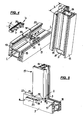
- Fig. 1
- eine perspektivische Ansicht einer Ausführungsform eines Basisteiles für einen erfindungsgemäßen Pfostenverbinder, noch vor dem Zusammenbau;
- Fig. 2
- eine schräge perspektivische Draufsicht auf ein Aufsetzteil zum Zusammenbau mit dem Basisteil gemäß
Fig. 1 ; - Fig. 3
- eine perspektivische Ansicht (von schräg unten) auf eine andere Ausführungsform des oberen Teilstückes des Basisteiles;
- Fig. 4
- eine perspektivische Schrägdarstellung eines Basisteiles der Ausführungsform gemäß
Fig. 1 , wobei die Grundplatte auf einer Rahmenleiste befestigt ist, noch vor Aufschieben des Pfostens und vor Befestigung des Ansatzteiles; - Fig. 5
- die Anordnung aus
Fig. 4 , jedoch nach Aufschieben des Pfostens, aber vor Einfügen des oberen Teilstücks des Basisteiles; - Fig. 6
- eine perspektivische Darstellung eines Basisteiles, jedoch mit dem oberen Teilstück gemäß
Fig. 3 , in montiertem Zustand auf einer Rahmenleiste mit noch nicht montiertem Pfosten; - Fig. 7
- eine Perspektivdarstellung des montierten Pfostenverbinders von der Rahmeninnenseite her gesehen, sowie
- Fig. 8
- eine Perspektivdarstellung des montierten Pfostenverbinders von der Rahmenaußenseite her gesehen.
- Fig. 1
- a perspective view of an embodiment of a base part for a post connector according to the invention, before assembly;
- Fig. 2
- an oblique perspective top view of a Aufsetzteil for assembly with the base part according to
Fig. 1 ; - Fig. 3
- a perspective view (obliquely from below) of another embodiment of the upper portion of the base part;
- Fig. 4
- a perspective oblique view of a base part of the embodiment according to
Fig. 1 , wherein the base plate is mounted on a frame strip, before pushing the post and before attachment of the attachment part; - Fig. 5
- the arrangement
Fig. 4 but after sliding the post, but before inserting the upper part of the base part; - Fig. 6
- a perspective view of a base part, but with the upper portion according to
Fig. 3 , in mounted condition on a frame strip with not yet mounted post; - Fig. 7
- a perspective view of the assembled post connector seen from the frame inside, as well
- Fig. 8
- a perspective view of the mounted post connector seen from the frame outside.
In den Figuren sind zwei Ausführungsbeispiele für einen erfindungsgemäßen Pfostenverbinder dargestellt, wobei in allen Figuren stets dieselben Bezugszeichen für die Bezeichnung derselben Teile verwendet werden.In the figures, two embodiments of a post connector according to the invention are shown, wherein in all figures always the same reference numerals for the designation of the same parts are used.
Der Pfostenverbinder besteht aus zwei Teilen, nämlich einem Basisteil 1, von dem eine Ausführungsform in perspektivischer Schrägdarstellung (von oben) in
Das Aufsetzteil 2 wird, wie etwa die
Zur Ausbildung des Pfostenverbinders werden das Basisteil 1 und das Aufsetzteil 2 zusammengefügt:
- Wie
Fig. 1 zeigt, sindim Grundkörper 3 des Basisteiles 1 senkrecht zur Längsachse L-L derRahmenleiste 5, auf welcher das Basisteil 1 später montiert wird, von dessen Oberseite her zwei zueinander parallele Führungsnuten 16 ausgebildet.
- As
Fig. 1 shows, in thebase body 3 of the base part 1 perpendicular to the longitudinal axis LL of theframe strip 5, on which the base part 1 is mounted later, from the top side two mutuallyparallel guide grooves 16 are formed.
Der Grundkörper 3 selbst bildet dabei im wesentlichen einen plattenförmigen Körper aus, der bei seiner Montage auf der Rahmenleiste 5 in einer oben auf dieser angebrachten Profilnut zwischen einem der Außenseite des Rahmens zugewandten Außenflansch 17 (auch als "Überschlag" bezeichnet) an der äußeren Längsseite der Rahmenleiste 5 und einer Nut 18 am gegenüberliegenden (inneren) Seitenrand der Rahmenleiste 5 angeordnet wird.The
Dabei erstreckt sich der Grundkörper 3 im wesentlichen senkrecht zur Längsrichtung L-L der Rahmenleiste 5 und hat in der Draufsicht eine im wesentlichen rechteckige Form (vgl.
Die Führungsnuten 16 auf der Oberseite des Grundkörpers 3 haben jeweils eine Tiefe t und erstrecken sich nahezu über den gesamten Verlauf des Grundkörpers 3 in senkrechter Querrichtung zur Längsachse L-L der Rahmenleiste 5.The
Wie
An seinem dem Außenflansch 17 zugewandten Ende ist der Grundkörper 3 mit einem vertikal nach oben wegragenden Steg 6 versehen, der senkrecht zur Oberfläche 20 des Grundkörpers 3 und zu den Führungsnuten 16 ausgerichtet ist. An seinem oberen Ende läuft, im montierten Zustand, rechtwinklig von ihm und parallel zum Grundkörper 3 eine Stützplatte 21 ab, die bei diesem Ausführungsbeispiel das Ansatzteil 4 bildet. Dabei steht die Stützplatte 21 vom Steg 6 so vor, daß sie (im montierten Zustand) die Oberseite des Außenflansches 17 vollständig überdeckt und sich auf dessen Oberfläche 22 mit ihrer Unterseite abstützt, wie dies für den montierten Zustand die
Auch die Stützplatte 21 erstreckt sich bei dem in
Wie in
Das zentrale Blockteil 23 des Aufsetzteiles 2 hat dabei eine Form und Größe, die im wesentlichen der Form und Größe des im zusammengebauten Zustand unter ihm liegenden Grundkörper 3 des Basisteiles 1 entspricht.The
Das zentrale Blockteil 23 ist auf seiner Unterseite mit einer unteren ebenen Stützfläche 24 versehen, von der zwei parallele, plattenförmige Leisten 25 senkrecht nach unten vorstehen. Die Leisten 25 sind dabei so angeordnet und ihr Überstand und ihre Breite so gewählt, daß sie im zusammengefügten Zustand von Basisteil 1 und Aufsetzteil 2 in die beiden Führungsnuten 16 formschlüssig eingreifen und diese im Montage-Endzustand nahezu vollständig ausfüllen. Dabei kann das Aufsetzteil 2 so dem Grundkörper 3 zugeführt werden, daß die Leisten 25 von der der Stützplatte 21 des Basisteiles gegenüberliegenden Seite des Grundkörpers 3 aus (also von der Rahmeninnenseite her) in die dort mündenden Führungsnuten 16 eingeschoben werden. Damit ist ein geführtes Aufbringen des Aufsetzteiles 2 senkrecht zur Längsachse L-L der Rahmenleiste 5 auf das Basisteil 1 gewährleistet, wobei die Unterseite 24 des Aufsetzteiles 2 auf der Oberfläche 22 des Grundkörpers 3 aufliegt.The
Es versteht sich, daß auch andere Formgestaltungen zur Ausbildung der formschlüssigen Führung des Aufsetzteiles 2 und des Basisteiles 1 möglich sind. So könnte z. B. anstatt der beiden Leisten 25 des Aufsetzteiles 2 und deren Führungsnuten 16 am Basisteil 1 an diesem auch eine Schwalbenschwanznut o. ä. ausgebildet sein, in die ein am Aufsetzteil 2 angebrachtes dem Nutquerschnitt entsprechend geformtes Führungsteil mit schwalbenschwanzförmigen Querschnitt einführbar und dort verschieblich aufgenommen ist. In diesem Fall müßten dann die Bohrungen 19 für Befestigungsschrauben beidseits der Schwalbenschwanznut angebracht werden.It is understood that other shapes for the formation of the positive guidance of the
Beim Aufsetzteil 2 schließt sich, wie
Wenn der Grundkörper 3 und das Aufsetzteil 2 des Pfostenverbinders aufeinander gesetzt sind, ist das Aufsetzteil 2 soweit relativ zum Grundkörper 3 verschoben, daß die dem Steg 6 zugewandte vordere Endfläche 30 seines zentralen Blockteiles 23 gegen die ihr zugewandte Anschlagfläche 31 des Steges 6 zur Anlage kommt, die gegenüber der Einschiebebewegung des Aufsetzteiles 2 einen Anschlag ausbildet.When the
An dem Basisteil 1 wie auch am Aufsetzteil 2 sind außerdem Bohrungen 32 so angebracht, daß im zusammengeschobenen Zustand eine durch den Grundkörper 3 und durch die Leisten 25 fluchtend hindurchlaufende Durchgangsbohrung 32 entsteht. Diese Durchgangsbohrung 32 läuft sowohl durch den Grundkörper 3, wie auch durch die Leisten 25 hindurch. Damit besteht die Möglichkeit, mittels eines geeigneten in die Durchlaufbohrung 32 eingebrachten Befestigungsmittels (etwa mittels einer entsprechend langen Schraube oder zweier Schrauben oder auch mittels anderer hindurchsteckbarer Komponenten, wie Spleißbolzen o. ä.) eine feste Verbindung zwischen Basisteil 1 und Aufsetzteil 2 zu schaffen, welche auch die Relativposition beider zueinander blockiert.On the base part 1 as well as on the mounting
Zur Montage eines Pfostenverbinders mit einem Basisteil entsprechend der Darstellung der
Daneben wird das Aufsetzteil 2 mit seinem oberen Formabschnitt 12 bis zum Anschlag seiner oberen Tragfläche 13 gegen die untere Abschlußfläche 15 des Pfostens 11 in dessen Hohlquerschnitt 14 eingeschoben und dort in geeigneter Weise, z. B. mittels durch die Bohrungen 28 hindurchgesteckter Schrauben, am Pfosten 11 befestigt (in den Figuren nicht dargestellt).In addition, the
Damit liegt die in
Nunmehr wird der Pfosten 11 mit dem an ihm unten befestigten Aufsetzteil 2 von der Innenseite des späteren Rahmens her mit seinen zwei parallelen unteren Leisten 25 in die Führungsnuten 16 im Grundkörper 3 des Basisteiles 1 eingeführt und dort, unter gleichzeitiger Auflage der Stützfläche 24 des zentralen Blockteiles 23 auf der zugewandten Oberfläche 20 am Grundkörper 3 des Basisteiles 1, so lange in Richtung auf den Steg 6 hin verschoben, bis die vordere Endfläche 30 des zentralen Blockteiles 23 gegen die zugewandte Fläche 31 des Steges 6 anliegt. Durch diese formschlüssig festgelegte und definierte Relativstellung von Basisteil 1 und Aufsetzteil 2 zueinander ist dann auch eine Durchgangsbohrung 32 durchgängig ausgebildet, so daß nunmehr seitlich durch Einschrauben entsprechender Schrauben das Basisteil 1 und das Aufsetzteil 2 des Pfostenverbinders miteinander verbunden und arretiert werden können.Now, the
Damit ist die in
Die Stützplatte 21 weist aber, wie
Die Stützplatte 21 des Ansatzteiles 4 weist auf ihrer Unterseite eine im wesentlichen glatte Oberfläche 34 auf, wie dies
Auf der Oberseite der Stützplatte 21 bildet diese eine schräg nach außen ansteigende Oberfläche 35, bestehend aus einer Vielzahl von Flächenstegen, aus, die als Auflagefläche für die Unterseite 15 des Außenflansches 22 des Pfostens 11 dient.On the upper side of the
Die untere Fläche 34 der Stützplatte 21 dient zur Auflage auf der Oberfläche 22 des Außenflansches 17 der Rahmenleiste 5.The
Die Ausrichtung der Flächen 34 und 35 zueinander ist so, daß sie, nach der Außenseite hin gesehen, um einen Winkel α divergieren (vgl.
Wie
Dies führt dazu, daß im montierten Zustand, wie die
Die umlaufende Abdeckleiste 36 ergibt, wie
Das abschließende Montieren des Ansatzteiles 4 in Form der Stützplatte 21 bei der Ausführungsform der Basisplatte 1 gemäß
Eine andere Form eines Basisteiles zeigt
Das Basisteil 1 in Form der Stützplatte 21 unterscheidet sich von dem Zustand aus
Hier besteht also das Ansatzteil 4 aus der Stützplatte 21 und dem Steg 6, die das zweite Einzelstück des Basisteiles 1 ausbilden.Here, therefore, there is the
Wie
Wie
Bei der Ausbildung des Ansatzteiles 4 in Form einer einstückigen Ausbildung von Steg 6 und Stützplatte 21 besteht allerdings nicht mehr die Möglichkeit, das Ansatzteil 4 in einem letzten Schritt zu montieren, nachdem vorher der Pfosten 11 mit dem Aufsetzteil 2 auf den Grundkörper 3 aufgeschoben wurde. Denn das Ansatzteil aus Stützplatte 21 und Steg 6 läßt sich dann durch den engen Spalt S zwischen Pfosten 11 und Rahmenleiste 5 nicht mehr von außen montieren.In the formation of the
Diesen Zustand mit einem solchen Basisteil 1 zeigt nun die perspektivische Darstellung der
Erst wenn das Basisteil 1 so, wie in
Claims (7)
Applications Claiming Priority (1)
| Application Number | Priority Date | Filing Date | Title |
|---|---|---|---|
| DE102010007181.1A DE102010007181B4 (en) | 2010-02-08 | 2010-02-08 | pinheader |
Publications (2)
| Publication Number | Publication Date |
|---|---|
| EP2354419A2 true EP2354419A2 (en) | 2011-08-10 |
| EP2354419A3 EP2354419A3 (en) | 2015-02-18 |
Family
ID=43903895
Family Applications (1)
| Application Number | Title | Priority Date | Filing Date |
|---|---|---|---|
| EP11000031.2A Withdrawn EP2354419A3 (en) | 2010-02-08 | 2011-01-04 | Post connector |
Country Status (3)
| Country | Link |
|---|---|
| EP (1) | EP2354419A3 (en) |
| DE (1) | DE102010007181B4 (en) |
| RU (1) | RU2011104130A (en) |
Cited By (7)
| Publication number | Priority date | Publication date | Assignee | Title |
|---|---|---|---|---|
| EP3124734A1 (en) * | 2015-07-30 | 2017-02-01 | PHI Technik für Fenster und Türen GmbH | Connection assembly for connecting a post on a frame profile of a window or a door made of plastic |
| DE102016123889A1 (en) | 2016-12-08 | 2018-06-14 | PHI Technik für Fenster und Türen GmbH | Connecting arrangement for connecting a post with a frame profile of a window or a door made of plastic |
| DE102017122328A1 (en) | 2017-09-26 | 2019-03-28 | PHI Technik für Fenster und Türen GmbH | Method and connection arrangement for connecting a post to a frame profile in a window or a door made of plastic |
| DE102018106525A1 (en) | 2018-03-20 | 2019-09-26 | PHI Technik für Fenster und Türen GmbH | joint assembly |
| DE202021106237U1 (en) | 2021-11-15 | 2021-11-25 | PHI Technik für Fenster und Türen GmbH | Connection arrangement for connecting a post to a frame profile of a window or door made of plastic |
| US20220341450A1 (en) * | 2021-04-21 | 2022-10-27 | Rhino Rack Australia Pty Limited | T-joint connector device |
| DE102021129760A1 (en) | 2021-11-15 | 2023-05-17 | PHI Technik für Fenster und Türen GmbH | Connection arrangement for connecting a post to a frame profile of a window or a door made of plastic |
Families Citing this family (2)
| Publication number | Priority date | Publication date | Assignee | Title |
|---|---|---|---|---|
| DE102010025055B4 (en) | 2010-06-25 | 2013-03-21 | PHI Technik für Fenster und Türen GmbH | pinheader |
| SE543388C2 (en) * | 2018-06-18 | 2020-12-29 | Munters Europe Ab | A connection device and a box arrangement provided with such connection device |
Citations (1)
| Publication number | Priority date | Publication date | Assignee | Title |
|---|---|---|---|---|
| DE202009003438U1 (en) | 2009-03-11 | 2009-05-28 | PHI Technik für Fenster und Türen GmbH | pinheader |
Family Cites Families (3)
| Publication number | Priority date | Publication date | Assignee | Title |
|---|---|---|---|---|
| DE9206625U1 (en) | 1992-05-15 | 1993-09-16 | Niemann Hans Dieter | Connection for angled hollow profile bars |
| DE9316308U1 (en) | 1993-10-27 | 1995-02-23 | Niemann Hans Dieter | Connector for angled frame bars |
| DE19734876A1 (en) * | 1997-08-12 | 1999-02-18 | Peter Willrich | Connecting element for joining hollow part and abutting profiled part |
-
2010
- 2010-02-08 DE DE102010007181.1A patent/DE102010007181B4/en active Active
-
2011
- 2011-01-04 EP EP11000031.2A patent/EP2354419A3/en not_active Withdrawn
- 2011-02-07 RU RU2011104130/03A patent/RU2011104130A/en not_active Application Discontinuation
Patent Citations (1)
| Publication number | Priority date | Publication date | Assignee | Title |
|---|---|---|---|---|
| DE202009003438U1 (en) | 2009-03-11 | 2009-05-28 | PHI Technik für Fenster und Türen GmbH | pinheader |
Cited By (7)
| Publication number | Priority date | Publication date | Assignee | Title |
|---|---|---|---|---|
| EP3124734A1 (en) * | 2015-07-30 | 2017-02-01 | PHI Technik für Fenster und Türen GmbH | Connection assembly for connecting a post on a frame profile of a window or a door made of plastic |
| DE102016123889A1 (en) | 2016-12-08 | 2018-06-14 | PHI Technik für Fenster und Türen GmbH | Connecting arrangement for connecting a post with a frame profile of a window or a door made of plastic |
| DE102017122328A1 (en) | 2017-09-26 | 2019-03-28 | PHI Technik für Fenster und Türen GmbH | Method and connection arrangement for connecting a post to a frame profile in a window or a door made of plastic |
| DE102018106525A1 (en) | 2018-03-20 | 2019-09-26 | PHI Technik für Fenster und Türen GmbH | joint assembly |
| US20220341450A1 (en) * | 2021-04-21 | 2022-10-27 | Rhino Rack Australia Pty Limited | T-joint connector device |
| DE202021106237U1 (en) | 2021-11-15 | 2021-11-25 | PHI Technik für Fenster und Türen GmbH | Connection arrangement for connecting a post to a frame profile of a window or door made of plastic |
| DE102021129760A1 (en) | 2021-11-15 | 2023-05-17 | PHI Technik für Fenster und Türen GmbH | Connection arrangement for connecting a post to a frame profile of a window or a door made of plastic |
Also Published As
| Publication number | Publication date |
|---|---|
| RU2011104130A (en) | 2012-08-20 |
| DE102010007181A1 (en) | 2011-08-11 |
| DE102010007181B4 (en) | 2018-03-01 |
| EP2354419A3 (en) | 2015-02-18 |
Similar Documents
| Publication | Publication Date | Title |
|---|---|---|
| DE102010007181B4 (en) | pinheader | |
| DE102009012438B4 (en) | pinheader | |
| EP0200760B1 (en) | Profiled bar for securing plates, especially glass plates, for showcases, sales dispensers, exhibition furniture or similar | |
| EP1643049B1 (en) | Construction with structural profiles | |
| DE102015112563A1 (en) | Connecting arrangement for connecting a post to a frame profile of a window or a door made of plastic | |
| EP1026357B1 (en) | Frame section member for wood-metal windows or doors | |
| AT509484B1 (en) | HOLDING DEVICE FOR CONNECTING PROFILES TO A FLAT WALL ELEMENT | |
| EP0801202B1 (en) | Lattice cross assembly device | |
| DE3200844A1 (en) | THERMAL INSULATING COMPOSITE PROFILE | |
| DE102008015989B3 (en) | Sill support for door frames for fastening thermoplastic frame profile of door frame to sill profile of door sill, has section with flat end surface for lateral attachment against flat end surface on one of two longitudinal ends | |
| DE202009003438U1 (en) | pinheader | |
| EP2754803B1 (en) | Espagnolette fitting for a window or door and driving rod for such an espagnolette fitting | |
| DE19719013C2 (en) | With a wall bracket, cross-sectionally U-shaped holding profile for a partition | |
| DE202012002574U1 (en) | pinheader | |
| DE2428510C3 (en) | Molding tool for the production of plastic profile parts | |
| EP1860250B1 (en) | Attachment seal | |
| DE102010025055B4 (en) | pinheader | |
| DE102007009667B4 (en) | profile construction | |
| EP1388627B1 (en) | Fixing device for a fitting | |
| DE102012005295B3 (en) | Post connector for mechanically connecting frame profiles of e.g. window, has base and mounting portions whose positive guide is formed such that mounting portion is pushed above outer flange when joining mounting portion and post | |
| DE8322475U1 (en) | Frame made of profile rods | |
| DE102008057276A1 (en) | Adapters for fixing solar modules, solar modules mounted with adapters and methods of fixing solar modules | |
| DE19853528A1 (en) | Assembly kit for connectors involves compensating part placed on ground beam, attachment, side part, and upright-connector | |
| DE19749624C2 (en) | Protective grille | |
| DE202012002712U1 (en) | pinheader |
Legal Events
| Date | Code | Title | Description |
|---|---|---|---|
| PUAI | Public reference made under article 153(3) epc to a published international application that has entered the european phase |
Free format text: ORIGINAL CODE: 0009012 |
|
| AK | Designated contracting states |
Kind code of ref document: A2 Designated state(s): AL AT BE BG CH CY CZ DE DK EE ES FI FR GB GR HR HU IE IS IT LI LT LU LV MC MK MT NL NO PL PT RO RS SE SI SK SM TR |
|
| AX | Request for extension of the european patent |
Extension state: BA ME |
|
| PUAL | Search report despatched |
Free format text: ORIGINAL CODE: 0009013 |
|
| AK | Designated contracting states |
Kind code of ref document: A3 Designated state(s): AL AT BE BG CH CY CZ DE DK EE ES FI FR GB GR HR HU IE IS IT LI LT LU LV MC MK MT NL NO PL PT RO RS SE SI SK SM TR |
|
| AX | Request for extension of the european patent |
Extension state: BA ME |
|
| RIC1 | Information provided on ipc code assigned before grant |
Ipc: E06B 3/964 20060101AFI20150109BHEP Ipc: E06B 3/968 20060101ALN20150109BHEP |
|
| STAA | Information on the status of an ep patent application or granted ep patent |
Free format text: STATUS: THE APPLICATION IS DEEMED TO BE WITHDRAWN |
|
| 18D | Application deemed to be withdrawn |
Effective date: 20150819 |