EP0807702A1 - Dispositif pour fixer un corps et ratière avec un tel dispositif - Google Patents
Dispositif pour fixer un corps et ratière avec un tel dispositif Download PDFInfo
- Publication number
- EP0807702A1 EP0807702A1 EP96810307A EP96810307A EP0807702A1 EP 0807702 A1 EP0807702 A1 EP 0807702A1 EP 96810307 A EP96810307 A EP 96810307A EP 96810307 A EP96810307 A EP 96810307A EP 0807702 A1 EP0807702 A1 EP 0807702A1
- Authority
- EP
- European Patent Office
- Prior art keywords
- support ring
- ring
- shaft drive
- carrier ring
- spread
- Prior art date
- Legal status (The legal status is an assumption and is not a legal conclusion. Google has not performed a legal analysis and makes no representation as to the accuracy of the status listed.)
- Withdrawn
Links
- 238000004519 manufacturing process Methods 0.000 description 5
- 238000009941 weaving Methods 0.000 description 3
- 238000005461 lubrication Methods 0.000 description 2
- 230000008878 coupling Effects 0.000 description 1
- 238000010168 coupling process Methods 0.000 description 1
- 238000005859 coupling reaction Methods 0.000 description 1
- 238000007373 indentation Methods 0.000 description 1
- 230000008407 joint function Effects 0.000 description 1
- 238000012423 maintenance Methods 0.000 description 1
- 230000004048 modification Effects 0.000 description 1
- 238000012986 modification Methods 0.000 description 1
- IHQKEDIOMGYHEB-UHFFFAOYSA-M sodium dimethylarsinate Chemical class [Na+].C[As](C)([O-])=O IHQKEDIOMGYHEB-UHFFFAOYSA-M 0.000 description 1
- 239000011343 solid material Substances 0.000 description 1
- 230000003313 weakening effect Effects 0.000 description 1
Images


Classifications
-
- F—MECHANICAL ENGINEERING; LIGHTING; HEATING; WEAPONS; BLASTING
- F16—ENGINEERING ELEMENTS AND UNITS; GENERAL MEASURES FOR PRODUCING AND MAINTAINING EFFECTIVE FUNCTIONING OF MACHINES OR INSTALLATIONS; THERMAL INSULATION IN GENERAL
- F16C—SHAFTS; FLEXIBLE SHAFTS; ELEMENTS OR CRANKSHAFT MECHANISMS; ROTARY BODIES OTHER THAN GEARING ELEMENTS; BEARINGS
- F16C11/00—Pivots; Pivotal connections
- F16C11/04—Pivotal connections
- F16C11/045—Pivotal connections with at least a pair of arms pivoting relatively to at least one other arm, all arms being mounted on one pin
-
- D—TEXTILES; PAPER
- D03—WEAVING
- D03C—SHEDDING MECHANISMS; PATTERN CARDS OR CHAINS; PUNCHING OF CARDS; DESIGNING PATTERNS
- D03C1/00—Dobbies
- D03C1/14—Features common to dobbies of different types
- D03C1/144—Features common to dobbies of different types linking to the heald frame
-
- D—TEXTILES; PAPER
- D03—WEAVING
- D03C—SHEDDING MECHANISMS; PATTERN CARDS OR CHAINS; PUNCHING OF CARDS; DESIGNING PATTERNS
- D03C5/00—Cam or other direct-acting shedding mechanisms, i.e. operating heald frames without intervening power-supplying devices
-
- F—MECHANICAL ENGINEERING; LIGHTING; HEATING; WEAPONS; BLASTING
- F16—ENGINEERING ELEMENTS AND UNITS; GENERAL MEASURES FOR PRODUCING AND MAINTAINING EFFECTIVE FUNCTIONING OF MACHINES OR INSTALLATIONS; THERMAL INSULATION IN GENERAL
- F16C—SHAFTS; FLEXIBLE SHAFTS; ELEMENTS OR CRANKSHAFT MECHANISMS; ROTARY BODIES OTHER THAN GEARING ELEMENTS; BEARINGS
- F16C2340/00—Apparatus for treating textiles
Definitions
- the invention relates to a device for fastening a body according to the preamble of claim 1 and a shaft drive with such a device.
- DE-A-31 31 740 describes a device of this type.
- This device comprises two parts arranged parallel to one another, a support ring and a screw body.
- the parts have indentations which are directed inwards and on which the body is arranged.
- a feeder has an internal thread. The parts and the body are pressed together by means of the threaded body.
- a disadvantage of this device is the effort involved in manufacturing and in particular in maintenance. To remove the support ring, after removing the screw body, at least one part must be bent out to such an extent that the support ring can be removed from the intake on the other part. There is therefore a risk that the part will be plastically deformed.
- the invention has for its object to provide a device for attaching a body, which is easy to assemble and inexpensive to manufacture.
- Devices of this type can be used in many ways within a weaving machine, in particular on devices which execute a relative movement and are arranged close to one another, e.g. Roller hoists for healds, drives for heald frames or the like.
- devices equipped therewith can be arranged very closely to one another.
- the device in question can be used at various points on a weaving machine.
- only two application examples are mentioned.
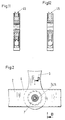
- FIGS. 1 and 2. 1 shows a device for moving up and down heald frames, which essentially consists of a drive device 1, shaft drive rods 2, toggle levers 3 and push rods 4.
- the heald frames are connected to the push rods 4 via couplings 5.
- the Shaft drive rods 2 and the push rods 4 are tubes with a rectangular cross section, while the toggle levers 3 are made of solid material.
- the tube has a recess 6 on each of the narrow sides in order to insert the toggle lever 3 and a bore 7 on the broad sides in order to accommodate the device.
- the toggle levers 3 are each articulated to a shaft drive rod 2 and to a push rod 4 (FIG. 2).
- the device according to the invention is provided.
- the linkage takes place via a bearing, e.g. a plain bearing, the body 8 and a sliding sleeve 9 made of plastic form the bearing parts.
- a bearing e.g. a plain bearing
- the body 8 and a sliding sleeve 9 made of plastic form the bearing parts.
- the device comprises a support ring 11 and first and second threaded sleeves 12, 13.
- the support ring 11 has a slot 14 which runs axially.
- the support ring is each provided with a countersink 15 on the end faces.
- the support ring has two sections forming a shoulder 16.
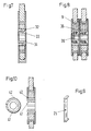
- the first threaded sleeve 12 has an internal thread 17 and a conical section 18 on one end face.
- a groove 24 is formed in the conical section 18 of the first threaded sleeve 12.
- the second threaded sleeve 13 has an external thread 19 that matches the internal thread of the first threaded sleeve 12 and an extension 20 with a conical section 21 on one end face.
- the second threaded sleeve 13 is provided with an internal hexagon 22.
- two recesses 23 are provided on the support ring 11 for inserting a tool (not shown).
- the toggle lever 3 equipped with the bearing part 8 and the sliding sleeve 9 is inserted into the recess 6, so that the bore in the bearing part 8 is aligned with the bores 7.
- the support ring 11 used, the ring being pulled together by means of a tool (not shown) and pushed into the bores.
- the support ring 11 assumes its original shape and then lies against the wall parts 2 of the square tube and against the bearing part 8.
- the first and second threaded sleeves 12, 13 are then inserted into the support ring 11 and screwed together.
- the conical sections 18, 21 of the threaded sleeves engage with the counterbores 15 in the support ring and spread the support ring or fix it.
- the support ring is pressed against the wall parts of the square tube 2 and against the bearing part 8, whereby the connection of the toggle lever 3 is made with the shaft drive rod 2 or the bumper.
- the shoulders 16 prevent axial slipping.
- An aid is provided to facilitate the assembly and disassembly of the device, which is shown in FIG. 9.
- This aid has an extension 25 which projects into the groove 24 (FIG. 4), so that the rotation of the first threaded sleeve 12 and the support ring 11 is prevented.
- the support ring 11 can be provided with a groove 26. With this weakening, a joint function is achieved, so that a three-point support wall part - bearing part - wall part can be achieved.
- a radially directed bore 35 is provided, which extends from the inner threaded sleeve to the sliding sleeve 9.
- FIG. 10 shows an embodiment in which an expansion ring 41 is inserted into a support ring 42 instead of threaded sleeves. This embodiment represents the cheapest or simplest solution in terms of manufacture, assembly and disassembly.
- this embodiment is suitable for mounting the strand rollers 45 in roller trains for jacquard machines, the strand rollers 45 being held rotatably between two webs arranged parallel to one another (FIGS. 11 and 12).
- the device has an expandable support ring 11 on which a body 8 is arranged and which is inserted into bores 7 and a connecting element 12, 13 which can be inserted into the support ring and is intended to spread the support ring.
- This device is inexpensive to manufacture and easy to assemble and is particularly suitable for connecting rotating parts with limited space.
Landscapes
- Engineering & Computer Science (AREA)
- General Engineering & Computer Science (AREA)
- Textile Engineering (AREA)
- Mechanical Engineering (AREA)
- Looms (AREA)
- Connection Of Plates (AREA)
- Pivots And Pivotal Connections (AREA)
Priority Applications (2)
| Application Number | Priority Date | Filing Date | Title |
|---|---|---|---|
| EP96810307A EP0807702A1 (fr) | 1996-05-15 | 1996-05-15 | Dispositif pour fixer un corps et ratière avec un tel dispositif |
| JP9125974A JPH1072737A (ja) | 1996-05-15 | 1997-05-15 | 物体を固定するための装置及びその装置を有する軸駆動装置 |
Applications Claiming Priority (1)
| Application Number | Priority Date | Filing Date | Title |
|---|---|---|---|
| EP96810307A EP0807702A1 (fr) | 1996-05-15 | 1996-05-15 | Dispositif pour fixer un corps et ratière avec un tel dispositif |
Publications (1)
| Publication Number | Publication Date |
|---|---|
| EP0807702A1 true EP0807702A1 (fr) | 1997-11-19 |
Family
ID=8225609
Family Applications (1)
| Application Number | Title | Priority Date | Filing Date |
|---|---|---|---|
| EP96810307A Withdrawn EP0807702A1 (fr) | 1996-05-15 | 1996-05-15 | Dispositif pour fixer un corps et ratière avec un tel dispositif |
Country Status (2)
| Country | Link |
|---|---|
| EP (1) | EP0807702A1 (fr) |
| JP (1) | JPH1072737A (fr) |
Cited By (8)
| Publication number | Priority date | Publication date | Assignee | Title |
|---|---|---|---|---|
| EP0943708A1 (fr) * | 1998-03-19 | 1999-09-22 | Stäubli Faverges | Mécanisme de tirage pour mécanique d'armure et métier à tisser comprenant un tel mécanisme de tirage |
| WO2004081270A1 (fr) * | 2003-03-12 | 2004-09-23 | Picanol N.V. | Systeme d'entrainement d'un moyen de formation de foule d'un metier mecanique |
| WO2006092260A1 (fr) * | 2005-02-28 | 2006-09-08 | Grosse Jac Webereimaschinen Gmbh | Element a poulies multiples utilise dans un metier jacquard |
| EP1881096A1 (fr) * | 2006-07-19 | 2008-01-23 | Groz-Beckert KG | Mécanisme d'entraînement des lames et tige de couplage |
| CN102851829A (zh) * | 2012-09-26 | 2013-01-02 | 吴江市隆泰喷织厂 | 方便调节导轨轴的固定装置 |
| FR3020842A1 (fr) * | 2014-05-09 | 2015-11-13 | Ct Tech Des Ind Mecaniques | Dispositif d'assemblage vissable |
| CN105862216A (zh) * | 2016-06-01 | 2016-08-17 | 江苏金铁人自动化科技有限公司 | 一种分体式连杆 |
| CN107109718A (zh) * | 2015-01-22 | 2017-08-29 | 米歇尔.范德威尔公司 | 安装在提花织机的滑轮机构中的滑轮 |
Families Citing this family (1)
| Publication number | Priority date | Publication date | Assignee | Title |
|---|---|---|---|---|
| JP3994897B2 (ja) * | 2003-03-18 | 2007-10-24 | 株式会社豊田自動織機 | 織機における開口装置 |
Citations (7)
| Publication number | Priority date | Publication date | Assignee | Title |
|---|---|---|---|---|
| US3227250A (en) * | 1962-04-02 | 1966-01-04 | United Shoe Machinery Corp | Disconnectible pivot joints for machine construction |
| CH571173A5 (fr) * | 1973-08-08 | 1975-12-31 | Staeubli Sa Des Ets France | |
| DE3131740A1 (de) * | 1980-08-12 | 1982-03-11 | Maschinenfabrik Rüti AG, 8630 Rüti, Zürich | Vorrichtung zur halterung eines koerpers zwischen zwei zueinander parallelen teilen |
| EP0241968A2 (fr) * | 1986-03-27 | 1987-10-21 | NUOVOPIGNONE INDUSTRIE MECCANICHE E FONDERIA S.p.A. | Tourillon démontable, en particulier pour le système de leviers dans les machines textiles |
| FR2621362A1 (fr) * | 1987-10-02 | 1989-04-07 | Nuovo Pignone Spa | Boulon demontable pour assembler de facon tournante l'un a l'autre deux elements mecaniques de petites dimensions axiales, particulierement pour des systemes de leviers de machines textiles |
| US5320443A (en) * | 1992-01-28 | 1994-06-14 | Commercial Intertech Corp. | Connecting pin |
| DE4427127C1 (de) * | 1994-07-30 | 1995-07-06 | Dornier Gmbh Lindauer | Schraubverbindung, insbesondere für Schaftgestänge von Webmaschinen |
-
1996
- 1996-05-15 EP EP96810307A patent/EP0807702A1/fr not_active Withdrawn
-
1997
- 1997-05-15 JP JP9125974A patent/JPH1072737A/ja active Pending
Patent Citations (7)
| Publication number | Priority date | Publication date | Assignee | Title |
|---|---|---|---|---|
| US3227250A (en) * | 1962-04-02 | 1966-01-04 | United Shoe Machinery Corp | Disconnectible pivot joints for machine construction |
| CH571173A5 (fr) * | 1973-08-08 | 1975-12-31 | Staeubli Sa Des Ets France | |
| DE3131740A1 (de) * | 1980-08-12 | 1982-03-11 | Maschinenfabrik Rüti AG, 8630 Rüti, Zürich | Vorrichtung zur halterung eines koerpers zwischen zwei zueinander parallelen teilen |
| EP0241968A2 (fr) * | 1986-03-27 | 1987-10-21 | NUOVOPIGNONE INDUSTRIE MECCANICHE E FONDERIA S.p.A. | Tourillon démontable, en particulier pour le système de leviers dans les machines textiles |
| FR2621362A1 (fr) * | 1987-10-02 | 1989-04-07 | Nuovo Pignone Spa | Boulon demontable pour assembler de facon tournante l'un a l'autre deux elements mecaniques de petites dimensions axiales, particulierement pour des systemes de leviers de machines textiles |
| US5320443A (en) * | 1992-01-28 | 1994-06-14 | Commercial Intertech Corp. | Connecting pin |
| DE4427127C1 (de) * | 1994-07-30 | 1995-07-06 | Dornier Gmbh Lindauer | Schraubverbindung, insbesondere für Schaftgestänge von Webmaschinen |
Cited By (13)
| Publication number | Priority date | Publication date | Assignee | Title |
|---|---|---|---|---|
| FR2776307A1 (fr) * | 1998-03-19 | 1999-09-24 | Staubli Sa Ets | Mecanisme de tirage pour mecanique d'armure et metier a tisser comprenant un tel mecanisme de tirage |
| US6145548A (en) * | 1998-03-19 | 2000-11-14 | Staubli Faverges | Connector for loom connecting rod and drawing mechanism |
| CN1084402C (zh) * | 1998-03-19 | 2002-05-08 | 史陶比尔-法韦日公司 | 织造系统用的拉伸机构和采用这种机构的织机 |
| EP0943708A1 (fr) * | 1998-03-19 | 1999-09-22 | Stäubli Faverges | Mécanisme de tirage pour mécanique d'armure et métier à tisser comprenant un tel mécanisme de tirage |
| WO2004081270A1 (fr) * | 2003-03-12 | 2004-09-23 | Picanol N.V. | Systeme d'entrainement d'un moyen de formation de foule d'un metier mecanique |
| CN101160422B (zh) * | 2005-02-28 | 2010-12-15 | 弘生集团有限公司 | 用于提花机的滑轮组部件 |
| WO2006092260A1 (fr) * | 2005-02-28 | 2006-09-08 | Grosse Jac Webereimaschinen Gmbh | Element a poulies multiples utilise dans un metier jacquard |
| EP1881096A1 (fr) * | 2006-07-19 | 2008-01-23 | Groz-Beckert KG | Mécanisme d'entraînement des lames et tige de couplage |
| CN102851829A (zh) * | 2012-09-26 | 2013-01-02 | 吴江市隆泰喷织厂 | 方便调节导轨轴的固定装置 |
| FR3020842A1 (fr) * | 2014-05-09 | 2015-11-13 | Ct Tech Des Ind Mecaniques | Dispositif d'assemblage vissable |
| CN107109718A (zh) * | 2015-01-22 | 2017-08-29 | 米歇尔.范德威尔公司 | 安装在提花织机的滑轮机构中的滑轮 |
| CN107109718B (zh) * | 2015-01-22 | 2020-06-09 | 米歇尔.范德威尔公司 | 安装在提花织机的滑轮机构中的滑轮 |
| CN105862216A (zh) * | 2016-06-01 | 2016-08-17 | 江苏金铁人自动化科技有限公司 | 一种分体式连杆 |
Also Published As
| Publication number | Publication date |
|---|---|
| JPH1072737A (ja) | 1998-03-17 |
Similar Documents
| Publication | Publication Date | Title |
|---|---|---|
| DE102007047860B3 (de) | Verbindungselement mit einer Schraube und einer daran unverlierbar angeordneten Hülse | |
| EP2325502B1 (fr) | Agencement et procédé pour relier un accessoire avec une table d'opération | |
| DE2755674C2 (de) | Befestigungsvorrichtung | |
| EP1869334A1 (fr) | Palier lisse, systeme de palier lisse et montage d'un systeme de palier lisse | |
| EP1426636A1 (fr) | Ecrou de support rapide | |
| DE29712206U1 (de) | Vorrichtung zum Anschluß einer elektrischen Leitung an einem Eisenbahnschienensteg o.dgl. | |
| DE4401622C2 (de) | Befestigungsvorrichtung für ein Montageglied einer Mutter-Schraube-Verbindung | |
| DE60218621T2 (de) | Befestigungsvorrichtung | |
| DE19949654B4 (de) | Toleranzausgleichselement | |
| DE4006028C2 (de) | Verbindungsbolzen und Anordnung aus Komponenten | |
| DE102019108910A1 (de) | Mehrteiliges Verstellelement für eine Toleranzausgleichsanordnung | |
| DE10034968A1 (de) | Befestigungsclip | |
| DE29825269U1 (de) | Rohrschelle mit Durchstoß-Mutter | |
| DE60103187T2 (de) | Sicherungsmutter | |
| EP0807702A1 (fr) | Dispositif pour fixer un corps et ratière avec un tel dispositif | |
| DE102009024264A1 (de) | Befestigungselement, insbesondere Mutter | |
| DE102005017746B4 (de) | Einbauanordnung für Antriebswellen in Kreuzgelenkgabeln | |
| DE102019115387A1 (de) | Spannvorrichtung zum Einspannen eines Gegenstands, insbesondere eines Werkzeugs | |
| DE102011005405A1 (de) | Befestigungsanordnung | |
| DE2340897A1 (de) | Halteeinrichtung fuer die polschuhe und dauermagnete einer dynamomaschine | |
| DE2234353A1 (de) | Federnde klammer | |
| DE102009005336A1 (de) | Schraubenelement, Schraubverbindung sowie Verfahren zum Herstellen eines Schraubenelementes | |
| EP1412117B1 (fr) | Element d'ecartement pour une pince de serrage et pince de serrage | |
| DE60121338T2 (de) | Verfahren und vorrichtung zum befestigen eines kolbens oder einer kolbenstangeverbindung an einer kolbenstange | |
| DE19842171B4 (de) | Rohrschelle |
Legal Events
| Date | Code | Title | Description |
|---|---|---|---|
| PUAI | Public reference made under article 153(3) epc to a published international application that has entered the european phase |
Free format text: ORIGINAL CODE: 0009012 |
|
| AK | Designated contracting states |
Kind code of ref document: A1 Designated state(s): BE DE FR IT |
|
| RBV | Designated contracting states (corrected) |
Designated state(s): BE DE FR IT |
|
| 17P | Request for examination filed |
Effective date: 19980422 |
|
| STAA | Information on the status of an ep patent application or granted ep patent |
Free format text: STATUS: THE APPLICATION IS DEEMED TO BE WITHDRAWN |
|
| 18D | Application deemed to be withdrawn |
Effective date: 19991201 |