EP0807702A1 - Device for fastening a body and dobby with such device - Google Patents
Device for fastening a body and dobby with such device Download PDFInfo
- Publication number
- EP0807702A1 EP0807702A1 EP96810307A EP96810307A EP0807702A1 EP 0807702 A1 EP0807702 A1 EP 0807702A1 EP 96810307 A EP96810307 A EP 96810307A EP 96810307 A EP96810307 A EP 96810307A EP 0807702 A1 EP0807702 A1 EP 0807702A1
- Authority
- EP
- European Patent Office
- Prior art keywords
- support ring
- ring
- shaft drive
- carrier ring
- spread
- Prior art date
- Legal status (The legal status is an assumption and is not a legal conclusion. Google has not performed a legal analysis and makes no representation as to the accuracy of the status listed.)
- Withdrawn
Links
- 238000004519 manufacturing process Methods 0.000 description 5
- 238000009941 weaving Methods 0.000 description 3
- 238000005461 lubrication Methods 0.000 description 2
- 230000008878 coupling Effects 0.000 description 1
- 238000010168 coupling process Methods 0.000 description 1
- 238000005859 coupling reaction Methods 0.000 description 1
- 238000007373 indentation Methods 0.000 description 1
- 230000008407 joint function Effects 0.000 description 1
- 238000012423 maintenance Methods 0.000 description 1
- 230000004048 modification Effects 0.000 description 1
- 238000012986 modification Methods 0.000 description 1
- IHQKEDIOMGYHEB-UHFFFAOYSA-M sodium dimethylarsinate Chemical class [Na+].C[As](C)([O-])=O IHQKEDIOMGYHEB-UHFFFAOYSA-M 0.000 description 1
- 239000011343 solid material Substances 0.000 description 1
- 230000003313 weakening effect Effects 0.000 description 1
Images


Classifications
-
- F—MECHANICAL ENGINEERING; LIGHTING; HEATING; WEAPONS; BLASTING
- F16—ENGINEERING ELEMENTS AND UNITS; GENERAL MEASURES FOR PRODUCING AND MAINTAINING EFFECTIVE FUNCTIONING OF MACHINES OR INSTALLATIONS; THERMAL INSULATION IN GENERAL
- F16C—SHAFTS; FLEXIBLE SHAFTS; ELEMENTS OR CRANKSHAFT MECHANISMS; ROTARY BODIES OTHER THAN GEARING ELEMENTS; BEARINGS
- F16C11/00—Pivots; Pivotal connections
- F16C11/04—Pivotal connections
- F16C11/045—Pivotal connections with at least a pair of arms pivoting relatively to at least one other arm, all arms being mounted on one pin
-
- D—TEXTILES; PAPER
- D03—WEAVING
- D03C—SHEDDING MECHANISMS; PATTERN CARDS OR CHAINS; PUNCHING OF CARDS; DESIGNING PATTERNS
- D03C1/00—Dobbies
- D03C1/14—Features common to dobbies of different types
- D03C1/144—Features common to dobbies of different types linking to the heald frame
-
- D—TEXTILES; PAPER
- D03—WEAVING
- D03C—SHEDDING MECHANISMS; PATTERN CARDS OR CHAINS; PUNCHING OF CARDS; DESIGNING PATTERNS
- D03C5/00—Cam or other direct-acting shedding mechanisms, i.e. operating heald frames without intervening power-supplying devices
-
- F—MECHANICAL ENGINEERING; LIGHTING; HEATING; WEAPONS; BLASTING
- F16—ENGINEERING ELEMENTS AND UNITS; GENERAL MEASURES FOR PRODUCING AND MAINTAINING EFFECTIVE FUNCTIONING OF MACHINES OR INSTALLATIONS; THERMAL INSULATION IN GENERAL
- F16C—SHAFTS; FLEXIBLE SHAFTS; ELEMENTS OR CRANKSHAFT MECHANISMS; ROTARY BODIES OTHER THAN GEARING ELEMENTS; BEARINGS
- F16C2340/00—Apparatus for treating textiles
Definitions
- the invention relates to a device for fastening a body according to the preamble of claim 1 and a shaft drive with such a device.
- DE-A-31 31 740 describes a device of this type.
- This device comprises two parts arranged parallel to one another, a support ring and a screw body.
- the parts have indentations which are directed inwards and on which the body is arranged.
- a feeder has an internal thread. The parts and the body are pressed together by means of the threaded body.
- a disadvantage of this device is the effort involved in manufacturing and in particular in maintenance. To remove the support ring, after removing the screw body, at least one part must be bent out to such an extent that the support ring can be removed from the intake on the other part. There is therefore a risk that the part will be plastically deformed.
- the invention has for its object to provide a device for attaching a body, which is easy to assemble and inexpensive to manufacture.
- Devices of this type can be used in many ways within a weaving machine, in particular on devices which execute a relative movement and are arranged close to one another, e.g. Roller hoists for healds, drives for heald frames or the like.
- devices equipped therewith can be arranged very closely to one another.
- the device in question can be used at various points on a weaving machine.
- only two application examples are mentioned.
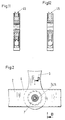
- FIGS. 1 and 2. 1 shows a device for moving up and down heald frames, which essentially consists of a drive device 1, shaft drive rods 2, toggle levers 3 and push rods 4.
- the heald frames are connected to the push rods 4 via couplings 5.
- the Shaft drive rods 2 and the push rods 4 are tubes with a rectangular cross section, while the toggle levers 3 are made of solid material.
- the tube has a recess 6 on each of the narrow sides in order to insert the toggle lever 3 and a bore 7 on the broad sides in order to accommodate the device.
- the toggle levers 3 are each articulated to a shaft drive rod 2 and to a push rod 4 (FIG. 2).
- the device according to the invention is provided.
- the linkage takes place via a bearing, e.g. a plain bearing, the body 8 and a sliding sleeve 9 made of plastic form the bearing parts.
- a bearing e.g. a plain bearing
- the body 8 and a sliding sleeve 9 made of plastic form the bearing parts.
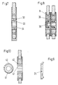
- the device comprises a support ring 11 and first and second threaded sleeves 12, 13.
- the support ring 11 has a slot 14 which runs axially.
- the support ring is each provided with a countersink 15 on the end faces.
- the support ring has two sections forming a shoulder 16.
- the first threaded sleeve 12 has an internal thread 17 and a conical section 18 on one end face.
- a groove 24 is formed in the conical section 18 of the first threaded sleeve 12.
- the second threaded sleeve 13 has an external thread 19 that matches the internal thread of the first threaded sleeve 12 and an extension 20 with a conical section 21 on one end face.
- the second threaded sleeve 13 is provided with an internal hexagon 22.
- two recesses 23 are provided on the support ring 11 for inserting a tool (not shown).
- the toggle lever 3 equipped with the bearing part 8 and the sliding sleeve 9 is inserted into the recess 6, so that the bore in the bearing part 8 is aligned with the bores 7.
- the support ring 11 used, the ring being pulled together by means of a tool (not shown) and pushed into the bores.
- the support ring 11 assumes its original shape and then lies against the wall parts 2 of the square tube and against the bearing part 8.
- the first and second threaded sleeves 12, 13 are then inserted into the support ring 11 and screwed together.
- the conical sections 18, 21 of the threaded sleeves engage with the counterbores 15 in the support ring and spread the support ring or fix it.
- the support ring is pressed against the wall parts of the square tube 2 and against the bearing part 8, whereby the connection of the toggle lever 3 is made with the shaft drive rod 2 or the bumper.
- the shoulders 16 prevent axial slipping.
- An aid is provided to facilitate the assembly and disassembly of the device, which is shown in FIG. 9.
- This aid has an extension 25 which projects into the groove 24 (FIG. 4), so that the rotation of the first threaded sleeve 12 and the support ring 11 is prevented.
- the support ring 11 can be provided with a groove 26. With this weakening, a joint function is achieved, so that a three-point support wall part - bearing part - wall part can be achieved.
- a radially directed bore 35 is provided, which extends from the inner threaded sleeve to the sliding sleeve 9.
- FIG. 10 shows an embodiment in which an expansion ring 41 is inserted into a support ring 42 instead of threaded sleeves. This embodiment represents the cheapest or simplest solution in terms of manufacture, assembly and disassembly.
- this embodiment is suitable for mounting the strand rollers 45 in roller trains for jacquard machines, the strand rollers 45 being held rotatably between two webs arranged parallel to one another (FIGS. 11 and 12).
- the device has an expandable support ring 11 on which a body 8 is arranged and which is inserted into bores 7 and a connecting element 12, 13 which can be inserted into the support ring and is intended to spread the support ring.
- This device is inexpensive to manufacture and easy to assemble and is particularly suitable for connecting rotating parts with limited space.
Landscapes
- Engineering & Computer Science (AREA)
- General Engineering & Computer Science (AREA)
- Textile Engineering (AREA)
- Mechanical Engineering (AREA)
- Connection Of Plates (AREA)
- Pivots And Pivotal Connections (AREA)
- Looms (AREA)
Abstract
Description
Die Erfindung betrifft eine Einrichtung zum Befestigen eines Körpers gemäss dem Oberbegriff des Anspruches 1 und einen Schafttrieb mit einer solchen Einrichtung.The invention relates to a device for fastening a body according to the preamble of
In der DE-A-31 31 740 ist eine Vorrichtung dieser Art beschrieben. Diese Vorrichtung umfasst zwei parallel zueinander angeordnete Teile, einen Tragring und einen Schraubkörper. Die Teile weisen Einzüge auf, die nach innen gerichtet sind und auf welchen der Körper angeordnet ist. Ein Einzug ist mit Innengewinde versehen. Mittels des Gewindekörpers werden die Teile und der Körper zusammengepresst.DE-A-31 31 740 describes a device of this type. This device comprises two parts arranged parallel to one another, a support ring and a screw body. The parts have indentations which are directed inwards and on which the body is arranged. A feeder has an internal thread. The parts and the body are pressed together by means of the threaded body.
Als nachteilig erweist sich bei dieser Vorrichtung der Aufwand bei der Herstellung und insbesondere bei der Wartung. Zum Entfernen des Tragringes ist nach dem Entfernen des Schraubkörpers mindestens ein Teil soweit herauszubiegen, dass der Tragring vom Einzug am anderen Teil abgezogen werden kann. Damit besteht die Gefahr, dass der Teil plastisch verformt wird.A disadvantage of this device is the effort involved in manufacturing and in particular in maintenance. To remove the support ring, after removing the screw body, at least one part must be bent out to such an extent that the support ring can be removed from the intake on the other part. There is therefore a risk that the part will be plastically deformed.
Der Erfindung liegt die Aufgabe zugrunde, eine Einrichtung zum Befestigen eines Körpers zu schaffen, welche einfach zu montieren und billig herstellbar ist.The invention has for its object to provide a device for attaching a body, which is easy to assemble and inexpensive to manufacture.
Diese Aufgabe wird erfindungsgemäss mit den Merkmalen des Anspruches 1 gelöst.This object is achieved according to the invention with the features of
Die Vorteile der Erfindung sind in der vereinfachten Herstellung und Montage und in der Anwendung innerhalb einer Webmaschine zu sehen.The advantages of the invention can be seen in the simplified manufacture and assembly and in use within a weaving machine.
Derartige Einrichtungen können vielfach innerhalb einer Webmaschine angewendet werden, insbesondere an Vorrichtungen, die eine Relativbewegung ausführen und eng beieinander liegend angeordnet sind, z.B. Rollenzüge für Litzen, Triebe für Webschäfte oder dgl..Devices of this type can be used in many ways within a weaving machine, in particular on devices which execute a relative movement and are arranged close to one another, e.g. Roller hoists for healds, drives for heald frames or the like.
Dadurch, dass die Einrichtung bündig mit den Aussenflächen der Abschnitte ist, können damit ausgerüstete Vorrichtungen sehr eng beieinander angeordnet werden.Because the device is flush with the outer surfaces of the sections, devices equipped therewith can be arranged very closely to one another.
Nachfolgend wird die Erfindung anhand der beiliegenden Zeichnungen erläutert.The invention is explained below with reference to the accompanying drawings.
Es zeigen:
- Fig. 1
- Eine räumliche Darstellung einer Antriebsvorrichtung für die Webschäfte;
- Fig. 2
- eine Ansicht in Richtung des Pfeiles "A" in Fig. 1;
- Fig. 3
- ein Schnitt entlang der Linie B-B in Fig. 2, welcher eine bevorzugte Ausführungsform einer erfindungsgemässen Einrichtung darstellt;
- Fig. 4
- die Einrichtung gemäss Fig. 3 in auseinander gezogener Darstellung;
- Fig. 5
- eine Ansicht eines Elementes der erfindungsgemässen Einrichtung;
- Fig. 6
- ein Schnitt entlang der Linie C-C in Fig. 5;
- Fig. 7
- ein Schnitt entlang der Linie B-B in Fig. 2, eine zweite Ausführungsform einer erfindungsgemässen Einrichtung;
- Fig. 8
- ein Schnitt entlang der Linie B-B in Fig. 2, eine dritte Ausführungsform einer erfindungsgemässen Einrichtung;
- Fig. 9
- eine räumliche Darstellung eines Hilfsmittels zur Montage und Demontage der Einrichtung;
- Fig. 10
- ein Schnitt durch eine vierte Ausführungsform einer erfindungsgemässen Einrichtung,
- Fig. 11
- die Einrichtung nach Fig. 10 für einen Rollenzug im Schnitt und
- Fig. 12
- ein Schnitt durch eine Modifikation der Ausführungsform gemäss Fig. 11.
- Fig. 1
- A spatial representation of a drive device for the heald frames;
- Fig. 2
- a view in the direction of arrow "A" in Fig. 1;
- Fig. 3
- a section along the line BB in Figure 2, which represents a preferred embodiment of a device according to the invention.
- Fig. 4
- 3 in an exploded view;
- Fig. 5
- a view of an element of the inventive device;
- Fig. 6
- a section along the line CC in Fig. 5;
- Fig. 7
- a section along the line BB in Figure 2, a second embodiment of an inventive device.
- Fig. 8
- a section along the line BB in Figure 2, a third embodiment of an inventive device.
- Fig. 9
- a spatial representation of an aid for assembly and disassembly of the device;
- Fig. 10
- 3 shows a section through a fourth embodiment of an inventive device,
- Fig. 11
- 10 for a roller train in section and
- Fig. 12
- 11 shows a section through a modification of the embodiment according to FIG. 11.
Wie bereits erwähnt, kann die hier in Rede stehende Einrichtung an verschiedenen Stellen einer Webmaschine eingesetzt werden. In der nachfolgenden Beschreibung werden lediglich zwei Anwendungsbeispiele genannt.As already mentioned, the device in question can be used at various points on a weaving machine. In the following description, only two application examples are mentioned.
Es wird auf die Figuren 1 und 2 Bezug genommen. Die Fig. 1 zeigt eine Einrichtung zum auf- und abbewegen von Webschäften, die im wesentlichen aus einer Antriebsvorrichtung 1, Schafttriebstangen 2, Kniehebeln 3 und Stossstäbe 4 besteht. Die Webschäfte sind über Kupplungen 5 mit den Stossstäbe 4 verbunden. Die Schafttriebstangen 2 und die Stossstäbe 4 sind Rohre mit rechteckigem Querschnitt, während die Kniehebel 3 aus Vollmaterial bestehen. An der Anlenkstelle weist das Rohr an den Schmalseiten jeweils eine Ausnehmung 6, um den Kniehebel 3 einzusetzen und an den Breitseiten jeweils eine Bohrung 7 auf, um die Einrichtung aufzunehmen. Die Kniehebel 3 sind jeweils an eine Schafttriebstange 2 und an eine Stossstäbe 4 angelenkt (Fig. 2).Reference is made to FIGS. 1 and 2. 1 shows a device for moving up and down heald frames, which essentially consists of a
Hierzu ist die erfindungsgemässe Einrichtung vorgesehen. Die Anlenkung erfolgt über ein Lager, z.B. ein Gleitlager, wobei der Körper 8 und eine Gleithülse 9 aus Kunststoff die Lagerteile bilden.For this purpose, the device according to the invention is provided. The linkage takes place via a bearing, e.g. a plain bearing, the
Es wird auf die Figuren 3 bis 5 Bezug genommen. Die Einrichtung umfasst einen Tragring 11 sowie eine erste und zweite Gewindehülse 12, 13. Der Tragring 11 weist einen Schlitz 14 auf, der axial verläuft. An den Stirnseiten ist der Tragring jeweils mit einer Ansenkung 15 versehen. Ferner weist der Tragring zwei eine Schulter 16 bildende Abschnitte auf. Die erste Gewindehülse 12 hat ein Innengewinde 17 und an einer Stirnseite einen konischen Abschnitt 18. Im konischen Abschnitt 18 der ersten Gewindehülse 12 ist eine Nut 24 ausgebildet. Die zweite Gewindehülse 13 hat ein zum Innengewinde der ersten Gewindehülse 12 passendes Aussengewinde 19 und an einer Stirnseite einen Ansatz 20 mit einem konischen Abschnitt 21. Die zweite Gewindehülse 13 ist mit einem Innensechskant 22 versehen. Ferner sind zwei Ausnehmungen 23 am Tragring 11 zum Einführen eines Werkzeuges (nicht dargestellt) vorgesehen.Reference is made to FIGS. 3 to 5. The device comprises a
Zur Montage wird der mit dem Lagerteil 8 und der Gleithülse 9 ausgerüstete Kniehebel 3 in die Ausnehmung 6 eingesetzt, so dass die Bohrung im Lagerteil 8 mit den Bohrungen 7 fluchten. Danach wird der Tragring 11 eingesetzt, wobei mittels eines Werkzeuges (nicht dargestellt) der Ring zusammengezogen und in die Bohrungen eingestossen wird. Nach der Freigabe nimmt der Tragring 11 seine ursprüngliche Form an und liegt dann an den Wandteilen 2 des Vierkantrohres und am Lagerteil 8 an. Danach werden die erste und zweite Gewindehülse 12, 13 in den Tragring 11 eingesetzt und miteinander verschraubt. Die konischen Abschnitte 18, 21 der Gewindehülsen kommen mit den Ansenkungen 15 im Tragring in Eingriff und spreizen den Tragring bzw. setzen diesen fest. Dadurch wird der Tragring gegen die Wandteile des Vierkantrohres 2 und gegen den Lagerteil 8 gepresst, womit die Verbindung des Kniehebels 3 mit der Schafttriebstange 2 oder dem Stossstab hergestellt ist. Die Schultern 16 verhindern ein axiales Verrutschen. Zur Erleichterung der Montage und Demontage der Einrichtung ist ein Hilfsmittel vorgesehen, das in Fig. 9 dargestellt ist. Dieses Hilfsmittel weist einen Ansatz 25 auf, der in die Nut 24 ragt (Fig. 4), so dass die Drehung der ersten Gewindehülse 12 und des Tragringes 11 verhindert wird.For assembly, the
Aus der vorstehenden Beschreibung ist die vorteilhafte Montage bzw. Demontage ersichtlich.The advantageous assembly and disassembly can be seen from the above description.
Wie die Figur 6 zeigt, kann der Tragring 11 mit einer Rille 26 versehen sein. Mit dieser Schwächung wird eine Gelenkfunktion erzielt, so dass eine Dreipunktauflage Wandteil - Lagerteil - Wandteil erzielt werden kann.As FIG. 6 shows, the
Bei der Ausführungsform gemäss Figur 7 ist anstelle der ersten und zweiten Gewindehülse gemäss Figuren 3 und 4 lediglich eine Gewindehülse 31 mit einem zylindrischen Aussengewinde vorgesehen. Die Spreizung des Tragringes 32 wird dadurch erreicht, dass am Tragring 32 ein konisches Innengewinde 33 vorgesehen wird. In diesem Fall muss lediglich die Gewindehülse 31 eingeschraubt werden, wodurch eine Vereinfachung erzielt wird. Gleichzeitig ist die untere Wandung der Schafttriebstange geschlossen, wodurch sich eine grössere Stabilität ergibt.In the embodiment according to FIG. 7, instead of the first and second threaded sleeves according to FIGS. 3 and 4, only one threaded
Um die Lagerschmierung zu ermöglichen, ist eine radial gerichtete Bohrung 35 vorgesehen, die sich ausgehend von der inneren Gewindehülse zu der Gleithülse 9 erstreckt. Mit dieser Ausführungsform kann eine gleichzeitige Schmierung von nebeneinander angeordneten Lagerstellen erzielt werden (Fig. 8).In order to enable bearing lubrication, a radially directed bore 35 is provided, which extends from the inner threaded sleeve to the sliding
Die Figur 10 zeigt eine Ausführungsform, bei welcher anstelle von Gewindehülsen ein Spreizring 41 in einen Tragring 42 eingesetzt wird. Diese Ausführungsform stellt in Hinblick auf die Herstellung bzw. Montage und Demontage die billigste bzw. einfachste Lösung dar.FIG. 10 shows an embodiment in which an
Neben der Anwendung beim Schafttrieb eignet sich diese Ausführungsform zur Montage der Litzenrollen 45 in Rollenzügen für Jaquardmaschinen, wobei die Litzenrollen 45 zwischen zwei parallel zueinander angeordneten Stegen drehbeweglich gehalten sind (Fig. 11 und 12).In addition to the use in shaft drives, this embodiment is suitable for mounting the
Die Einrichtung weist einen spreizbaren Tragring 11, auf dem ein Körper 8 angeordnet ist und der in Bohrungen 7 eingesetzt ist und ein Verbindungselement 12, 13 auf, das in den Tragring einsetzbar und dazu bestimmt ist, den Tragring zu spreizen. Diese Einrichtung ist billig herstellbar und einfach montierbar und eignet sich insbesondere zur Verbindung von drehbeweglichen Teilen bei eingeschränkten Platzverhältnissen.The device has an
Claims (10)
Priority Applications (2)
| Application Number | Priority Date | Filing Date | Title |
|---|---|---|---|
| EP96810307A EP0807702A1 (en) | 1996-05-15 | 1996-05-15 | Device for fastening a body and dobby with such device |
| JP9125974A JPH1072737A (en) | 1996-05-15 | 1997-05-15 | Equipment for fixing article and shaft driving equipment having the same |
Applications Claiming Priority (1)
| Application Number | Priority Date | Filing Date | Title |
|---|---|---|---|
| EP96810307A EP0807702A1 (en) | 1996-05-15 | 1996-05-15 | Device for fastening a body and dobby with such device |
Publications (1)
| Publication Number | Publication Date |
|---|---|
| EP0807702A1 true EP0807702A1 (en) | 1997-11-19 |
Family
ID=8225609
Family Applications (1)
| Application Number | Title | Priority Date | Filing Date |
|---|---|---|---|
| EP96810307A Withdrawn EP0807702A1 (en) | 1996-05-15 | 1996-05-15 | Device for fastening a body and dobby with such device |
Country Status (2)
| Country | Link |
|---|---|
| EP (1) | EP0807702A1 (en) |
| JP (1) | JPH1072737A (en) |
Cited By (8)
| Publication number | Priority date | Publication date | Assignee | Title |
|---|---|---|---|---|
| EP0943708A1 (en) * | 1998-03-19 | 1999-09-22 | Stäubli Faverges | Traction device for shedding mechanisms and loom with such a device |
| WO2004081270A1 (en) * | 2003-03-12 | 2004-09-23 | Picanol N.V. | Drive system for shedding means pertaining to a mechanical weaving loom |
| WO2006092260A1 (en) * | 2005-02-28 | 2006-09-08 | Grosse Jac Webereimaschinen Gmbh | Tractive pulley element for a jacquard machine |
| EP1881096A1 (en) * | 2006-07-19 | 2008-01-23 | Groz-Beckert KG | Shaft drive assembly and coupling bar |
| CN102851829A (en) * | 2012-09-26 | 2013-01-02 | 吴江市隆泰喷织厂 | Fixing device capable of regulating guide rail shafts conveniently |
| FR3020842A1 (en) * | 2014-05-09 | 2015-11-13 | Ct Tech Des Ind Mecaniques | ASSEMBLY DEVICE |
| CN105862216A (en) * | 2016-06-01 | 2016-08-17 | 江苏金铁人自动化科技有限公司 | Split type connecting rod |
| CN107109718A (en) * | 2015-01-22 | 2017-08-29 | 米歇尔.范德威尔公司 | Pulley in the pulley mechanism of jacquard loom |
Families Citing this family (1)
| Publication number | Priority date | Publication date | Assignee | Title |
|---|---|---|---|---|
| JP3994897B2 (en) * | 2003-03-18 | 2007-10-24 | 株式会社豊田自動織機 | Opening device in loom |
Citations (7)
| Publication number | Priority date | Publication date | Assignee | Title |
|---|---|---|---|---|
| US3227250A (en) * | 1962-04-02 | 1966-01-04 | United Shoe Machinery Corp | Disconnectible pivot joints for machine construction |
| CH571173A5 (en) * | 1973-08-08 | 1975-12-31 | Staeubli Sa Des Ets France | |
| DE3131740A1 (en) * | 1980-08-12 | 1982-03-11 | Maschinenfabrik Rüti AG, 8630 Rüti, Zürich | Device for mounting a body between two mutually parallel parts |
| EP0241968A2 (en) * | 1986-03-27 | 1987-10-21 | NUOVOPIGNONE INDUSTRIE MECCANICHE E FONDERIA S.p.A. | Improved demountable pin, particularly suitable for the lever mechanisms of textile machines |
| FR2621362A1 (en) * | 1987-10-02 | 1989-04-07 | Nuovo Pignone Spa | REMOVABLE BOLT FOR JOINING TWO MECHANICAL ELEMENTS OF SMALL AXIAL DIMENSIONS, PARTICULARLY FOR TEXTILE MACHINE LEVER SYSTEMS |
| US5320443A (en) * | 1992-01-28 | 1994-06-14 | Commercial Intertech Corp. | Connecting pin |
| DE4427127C1 (en) * | 1994-07-30 | 1995-07-06 | Dornier Gmbh Lindauer | Screw connection for shank rod systems of looms |
-
1996
- 1996-05-15 EP EP96810307A patent/EP0807702A1/en not_active Withdrawn
-
1997
- 1997-05-15 JP JP9125974A patent/JPH1072737A/en active Pending
Patent Citations (7)
| Publication number | Priority date | Publication date | Assignee | Title |
|---|---|---|---|---|
| US3227250A (en) * | 1962-04-02 | 1966-01-04 | United Shoe Machinery Corp | Disconnectible pivot joints for machine construction |
| CH571173A5 (en) * | 1973-08-08 | 1975-12-31 | Staeubli Sa Des Ets France | |
| DE3131740A1 (en) * | 1980-08-12 | 1982-03-11 | Maschinenfabrik Rüti AG, 8630 Rüti, Zürich | Device for mounting a body between two mutually parallel parts |
| EP0241968A2 (en) * | 1986-03-27 | 1987-10-21 | NUOVOPIGNONE INDUSTRIE MECCANICHE E FONDERIA S.p.A. | Improved demountable pin, particularly suitable for the lever mechanisms of textile machines |
| FR2621362A1 (en) * | 1987-10-02 | 1989-04-07 | Nuovo Pignone Spa | REMOVABLE BOLT FOR JOINING TWO MECHANICAL ELEMENTS OF SMALL AXIAL DIMENSIONS, PARTICULARLY FOR TEXTILE MACHINE LEVER SYSTEMS |
| US5320443A (en) * | 1992-01-28 | 1994-06-14 | Commercial Intertech Corp. | Connecting pin |
| DE4427127C1 (en) * | 1994-07-30 | 1995-07-06 | Dornier Gmbh Lindauer | Screw connection for shank rod systems of looms |
Cited By (13)
| Publication number | Priority date | Publication date | Assignee | Title |
|---|---|---|---|---|
| FR2776307A1 (en) * | 1998-03-19 | 1999-09-24 | Staubli Sa Ets | DRAWING MECHANISM FOR ARMOR AND WEAVING MECHANISM COMPRISING SUCH A DRAWING MECHANISM |
| US6145548A (en) * | 1998-03-19 | 2000-11-14 | Staubli Faverges | Connector for loom connecting rod and drawing mechanism |
| CN1084402C (en) * | 1998-03-19 | 2002-05-08 | 史陶比尔-法韦日公司 | Drawing mechanism for weaving system and weaving loom incorporating such drawing mechanism |
| EP0943708A1 (en) * | 1998-03-19 | 1999-09-22 | Stäubli Faverges | Traction device for shedding mechanisms and loom with such a device |
| WO2004081270A1 (en) * | 2003-03-12 | 2004-09-23 | Picanol N.V. | Drive system for shedding means pertaining to a mechanical weaving loom |
| CN101160422B (en) * | 2005-02-28 | 2010-12-15 | 弘生集团有限公司 | Tractive pulley element for a jacquard machine |
| WO2006092260A1 (en) * | 2005-02-28 | 2006-09-08 | Grosse Jac Webereimaschinen Gmbh | Tractive pulley element for a jacquard machine |
| EP1881096A1 (en) * | 2006-07-19 | 2008-01-23 | Groz-Beckert KG | Shaft drive assembly and coupling bar |
| CN102851829A (en) * | 2012-09-26 | 2013-01-02 | 吴江市隆泰喷织厂 | Fixing device capable of regulating guide rail shafts conveniently |
| FR3020842A1 (en) * | 2014-05-09 | 2015-11-13 | Ct Tech Des Ind Mecaniques | ASSEMBLY DEVICE |
| CN107109718A (en) * | 2015-01-22 | 2017-08-29 | 米歇尔.范德威尔公司 | Pulley in the pulley mechanism of jacquard loom |
| CN107109718B (en) * | 2015-01-22 | 2020-06-09 | 米歇尔.范德威尔公司 | Pulley mounted in pulley mechanism of jacquard loom |
| CN105862216A (en) * | 2016-06-01 | 2016-08-17 | 江苏金铁人自动化科技有限公司 | Split type connecting rod |
Also Published As
| Publication number | Publication date |
|---|---|
| JPH1072737A (en) | 1998-03-17 |
Similar Documents
| Publication | Publication Date | Title |
|---|---|---|
| DE102007047860B3 (en) | Connecting element, e.g. for automobile, has bolt, non-removable sleeve with first narrow point, second narrow point with radially sprung element(s) that engage thread in force- and/or shape-locking manner and axially continuous slot or gap | |
| EP2325502B1 (en) | Assembly and method for connecting an accessory with an operating table | |
| DE2755674C2 (en) | Fastening device | |
| EP1869334A1 (en) | Slide bearing, slide bearing system and assembly of a slide bearing system | |
| EP1426636A1 (en) | Quick mounting nut | |
| DE29712206U1 (en) | Device for connecting an electrical line to a railroad track or the like. | |
| DE4401622C2 (en) | Fastening device for a mounting member of a nut-screw connection | |
| DE60218621T2 (en) | fastening device | |
| DE19949654B4 (en) | Tolerance compensation element | |
| DE102019108910A1 (en) | Multi-part adjustment element for a tolerance compensation arrangement | |
| DE10034968A1 (en) | Component fixer clip has fixer leg forming tie element for friction entrainment during screwing in to apply pull on screw against screwing direction. | |
| DE29825269U1 (en) | Pipe clamp with push-through nut | |
| DE60103187T2 (en) | locknut | |
| EP0807702A1 (en) | Device for fastening a body and dobby with such device | |
| DE4006028A1 (en) | Connecting bolt for machine elements | |
| DE102009024264A1 (en) | Fastener i.e. nut, for screwing-on threaded bolt, has borehole with attachment areas, which exhibit inner diameters adapted to different standard thread diameters of threaded bolt, respectively | |
| DE102005017746B4 (en) | Installation arrangement for drive shafts in universal joint yokes | |
| DE102019115387A1 (en) | Clamping device for clamping an object, in particular a tool | |
| DE102011005405A1 (en) | mounting assembly | |
| DE2340897A1 (en) | HOLDING DEVICE FOR THE POLE SHOES AND PERMANENT MAGNETS OF A DYNAMOMACHINE | |
| DE2234353A1 (en) | SPRING CLAMP | |
| DE102009005336A1 (en) | Screw element, screw connection and method for producing a screw element | |
| EP1412117B1 (en) | Spacer element for a collet chuck and collet chuck | |
| DE60121338T2 (en) | METHOD AND DEVICE FOR ATTACHING A PISTON OR A PISTON CONNECTOR TO A PISTON ROD | |
| DE19842171B4 (en) | pipe clamp |
Legal Events
| Date | Code | Title | Description |
|---|---|---|---|
| PUAI | Public reference made under article 153(3) epc to a published international application that has entered the european phase |
Free format text: ORIGINAL CODE: 0009012 |
|
| AK | Designated contracting states |
Kind code of ref document: A1 Designated state(s): BE DE FR IT |
|
| RBV | Designated contracting states (corrected) |
Designated state(s): BE DE FR IT |
|
| 17P | Request for examination filed |
Effective date: 19980422 |
|
| STAA | Information on the status of an ep patent application or granted ep patent |
Free format text: STATUS: THE APPLICATION IS DEEMED TO BE WITHDRAWN |
|
| 18D | Application deemed to be withdrawn |
Effective date: 19991201 |