EP0241968A2 - Improved demountable pin, particularly suitable for the lever mechanisms of textile machines - Google Patents
Improved demountable pin, particularly suitable for the lever mechanisms of textile machines Download PDFInfo
- Publication number
- EP0241968A2 EP0241968A2 EP87200553A EP87200553A EP0241968A2 EP 0241968 A2 EP0241968 A2 EP 0241968A2 EP 87200553 A EP87200553 A EP 87200553A EP 87200553 A EP87200553 A EP 87200553A EP 0241968 A2 EP0241968 A2 EP 0241968A2
- Authority
- EP
- European Patent Office
- Prior art keywords
- frusto
- pin
- taper
- conical
- nuts
- Prior art date
- Legal status (The legal status is an assumption and is not a legal conclusion. Google has not performed a legal analysis and makes no representation as to the accuracy of the status listed.)
- Granted
Links
Images

Classifications
-
- F—MECHANICAL ENGINEERING; LIGHTING; HEATING; WEAPONS; BLASTING
- F16—ENGINEERING ELEMENTS AND UNITS; GENERAL MEASURES FOR PRODUCING AND MAINTAINING EFFECTIVE FUNCTIONING OF MACHINES OR INSTALLATIONS; THERMAL INSULATION IN GENERAL
- F16C—SHAFTS; FLEXIBLE SHAFTS; ELEMENTS OR CRANKSHAFT MECHANISMS; ROTARY BODIES OTHER THAN GEARING ELEMENTS; BEARINGS
- F16C11/00—Pivots; Pivotal connections
- F16C11/02—Trunnions; Crank-pins
-
- D—TEXTILES; PAPER
- D03—WEAVING
- D03C—SHEDDING MECHANISMS; PATTERN CARDS OR CHAINS; PUNCHING OF CARDS; DESIGNING PATTERNS
- D03C1/00—Dobbies
-
- D—TEXTILES; PAPER
- D03—WEAVING
- D03C—SHEDDING MECHANISMS; PATTERN CARDS OR CHAINS; PUNCHING OF CARDS; DESIGNING PATTERNS
- D03C5/00—Cam or other direct-acting shedding mechanisms, i.e. operating heald frames without intervening power-supplying devices
-
- F—MECHANICAL ENGINEERING; LIGHTING; HEATING; WEAPONS; BLASTING
- F16—ENGINEERING ELEMENTS AND UNITS; GENERAL MEASURES FOR PRODUCING AND MAINTAINING EFFECTIVE FUNCTIONING OF MACHINES OR INSTALLATIONS; THERMAL INSULATION IN GENERAL
- F16C—SHAFTS; FLEXIBLE SHAFTS; ELEMENTS OR CRANKSHAFT MECHANISMS; ROTARY BODIES OTHER THAN GEARING ELEMENTS; BEARINGS
- F16C11/00—Pivots; Pivotal connections
- F16C11/04—Pivotal connections
- F16C11/045—Pivotal connections with at least a pair of arms pivoting relatively to at least one other arm, all arms being mounted on one pin
-
- F—MECHANICAL ENGINEERING; LIGHTING; HEATING; WEAPONS; BLASTING
- F16—ENGINEERING ELEMENTS AND UNITS; GENERAL MEASURES FOR PRODUCING AND MAINTAINING EFFECTIVE FUNCTIONING OF MACHINES OR INSTALLATIONS; THERMAL INSULATION IN GENERAL
- F16C—SHAFTS; FLEXIBLE SHAFTS; ELEMENTS OR CRANKSHAFT MECHANISMS; ROTARY BODIES OTHER THAN GEARING ELEMENTS; BEARINGS
- F16C2340/00—Apparatus for treating textiles
Definitions
- This invention relates to a new type of demountable pin, which is constructionally simple and economical and able to support large alternating loads without any danger of slackening by virtue of being self-locking, if requiring only a small tightening torque and can be demounted and remounted an indefinite number of times as it provides no permanent deformation or impression on the contacting surfaces
- the pin according to the invention can be formed with a very small axial dimension, it is particularly suitable for the lever mechanisms of textile machines.
- One of said known demountable pins consists of a screw with a frusto-conical head underside and having an internal hexagonal bore for its tightening by a key, and a nut also provided with a frusto-conical head underside.
- the two frusto-conical head undersides of the screw and nut engage two frusto-conical flares press-formed in one end of each of two opposing plate metal cheeks forming a first element, between which an end of a second element to be rotatably connected is inserted, and which for this purpose comprises in correspondence with the screw passage bore a bearing or bush.
- the nut which is completely embedded in the respective flare, has no possibility of remaining gripped while the system is being tightened (during any tightening procedure the nut is generally held with a wrench so that it does not rotate) so that in order to prevent the nut rotating, its frusto-conical head underside is generally provided with knurling disposed along the generating lines of the cone frustum to engage the frusto-conical flare of the plate metal cheek and thus prevent the nut rotating.
- this knurling bites into the said flare as the system is tightened, to mark it irreversibly with a permanent deformation which with the passage of time worsens the connection and therefore does not allow indefinite tightening and untightening of the pin.
- the frusto-conical underside of the screw head rotates and slides against the respective cheek flare to create burnishing or scoring which deteriorates said flare.
- the said sliding underside of the head has a diameter which is more than double the diameter of the screw thread, the result is that during tightening, that friction torque which is generated in the sliding zone and which has to be overcome by the torque key for tightening purposes is approximately double the uneliminable torque which originates from the screw thread friction alone.
- the object of the present invention is to obviate the aforesaid drawbacks by providing a demountable pin of simple and economical construction which is able to store a considerable amount of elastic energy while being contained within very small axial dimensions, and which undergoes no slippage of any sort during tightening.
- the pin formed in this manner also has the advantage of being able to be tightened and untightened on either side, and moreover as its two nuts have the same identical shape said nuts can be obtained from the same pressing with consequent evident economic advantage.
- the two end nuts of high-strength pressed steel each have a structure consisting of an internally threaded, substantially cylindrical annular part which is provided externally, at one end, with an annular flange having a frusto-conical surface and a thickness which decreases in an outward direction, its taper being greater by a few degrees than the taper of the corresponding frusto-conical flare of the cheek.
- the nut has a very elastic flexible flange which by having a greater taper than the frusto-conical flare of the cheek into which it is to be inserted is compelled to bend during tightening until it perfectly mates with the frusto-conical edge of said flare to thus undergo elastic deformation and store energy.
- pins constructed in this manner are able to withstand alternating loads of some thousands of kilograms indefinately, ie loads of an order of magnitude greater than that heretofore attained, without slackening occurring in the connection.
- the demountable pin to be inserted and clamped between two frusto-conical flares formed by pressing in one end of each of two opposing plate metal cheeks forming a first element and between which there is inserted an end of a second element to be rotatably connected thereto and which for this purpose comprises a bearing in correspondence with the pin passage bore, is characterised according to the present invention by consisting of a central stay bolt having an internal hexagonal through bore for its tightening by a key, and comprising in correspondence with its two ends two opposite-handed threads, right handed and left handed respectively, which are arranged to cooperate with the corresponding inner threads provided in two end nuts each of identical structure consisting of an internally threaded, substantially cylindrical annular part which is provided externally, at one end, with an annular flange having a frusto-conical surface and a thickness which decreases in an outward direction, its taper being greater than the taper of said frusto-conical flares of the cheeks forming said first element.
- the demountable pin is not only limited to connecting a facing-cheek element to another element, but can be applied in any field, from structural steel work to linkage work, in which large loads have to be withstood without the danger of slackening.
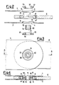
- the reference numerals 1 and 2 indicate respectively the ends of two opposing plate metal cheeks pertaining to a first element and comprising two flares 3, 4, respectively, formed by pressing and having frusto-conical surfaces 5.
- a second element 6 which is to be rotatably connected thereto and comprises in an appropriate hole 7 a roller bearing 8 having an inner track 9 with a double frusto-conical surface so as to exactly mate with the outer faces 5 ⁇ of the frusto-conical projections 5 of the flares 3 and 4.
- the two elements 1-2 and 6 are clamped together by a pin passing through the holes 3, 4 and 7 and consisting of a central stay bolt 10 having in its interior a hexagonal through bore 11 which enables it to be rotated from both ends by a key, and on its exterior a right handed thread 12, as has the end nut 13, and a left handed thread 14, as has the end nut 15.
- the two said end nuts 13 and 15 are substantially identical and are each formed of a cylindrical annular part 16 comprising said thread internally and provided at its outer end with an annular flange 17 having a frusto-conical surface and a thickness which decreases in an outward direction (see Figure 5 specifically).
- said annular flange 17 of the nuts 13 and 15 has a taper which exceeds by a certain angle ⁇ that of the inner frusto-conical surface 5 of the flares 3 and 4, so that during tightening, said flange is compelled to bend though an equal angle ⁇ , of about 2 ⁇ 3 degrees, to thus deform elastically and displace said frusto-conical surface 5, to reach the final position shown by dashed lines in the figure and indicated by 13 ⁇ .
Landscapes
- Engineering & Computer Science (AREA)
- General Engineering & Computer Science (AREA)
- Textile Engineering (AREA)
- Mechanical Engineering (AREA)
- Pivots And Pivotal Connections (AREA)
- Bolts, Nuts, And Washers (AREA)
- Clamps And Clips (AREA)
- Mutual Connection Of Rods And Tubes (AREA)
Abstract
Description
- This invention relates to a new type of demountable pin, which is constructionally simple and economical and able to support large alternating loads without any danger of slackening by virtue of being self-locking, if requiring only a small tightening torque and can be demounted and remounted an indefinite number of times as it provides no permanent deformation or impression on the contacting surfaces
- As the pin according to the invention can be formed with a very small axial dimension, it is particularly suitable for the lever mechanisms of textile machines.
- In this respect, in modern looms it is well known that the heddle frames are raised and lowered by trains of adjacent lever mechanisms which, for reasons of standardisation, have an axial pitch which is generally of 12 millimetres.
- The requirement for ever increasing loom speeds makes it necessary to construct pins having axial dimensions not exceeding 12 mm, but which are able to support increasingly large alternating loads with absolute security against slackening and thus able to store an adequate and sufficient elastic energy during their tightening.
- Various types of pin, some of which are demountable, are known in the current state of the art. One of said known demountable pins consists of a screw with a frusto-conical head underside and having an internal hexagonal bore for its tightening by a key, and a nut also provided with a frusto-conical head underside. The two frusto-conical head undersides of the screw and nut engage two frusto-conical flares press-formed in one end of each of two opposing plate metal cheeks forming a first element, between which an end of a second element to be rotatably connected is inserted, and which for this purpose comprises in correspondence with the screw passage bore a bearing or bush. This and all other known concepts have however a series of drawbacks which are magnified when the pin has to remain dimensionally contained within a small axial length of the order of 12 mm. Of these drawbacks, the worst is without doubt the fact that because of the small squat dimensions of the pin, it cannot be made to deform appreciably to store a sufficient amount of elastic energy to secure against slackening of the connection when large alternating loads are present.
- On the other hand the nut, which is completely embedded in the respective flare, has no possibility of remaining gripped while the system is being tightened (during any tightening procedure the nut is generally held with a wrench so that it does not rotate) so that in order to prevent the nut rotating, its frusto-conical head underside is generally provided with knurling disposed along the generating lines of the cone frustum to engage the frusto-conical flare of the plate metal cheek and thus prevent the nut rotating. However, this knurling bites into the said flare as the system is tightened, to mark it irreversibly with a permanent deformation which with the passage of time worsens the connection and therefore does not allow indefinite tightening and untightening of the pin.
- Moreover, during tightening, the frusto-conical underside of the screw head rotates and slides against the respective cheek flare to create burnishing or scoring which deteriorates said flare. As the said sliding underside of the head has a diameter which is more than double the diameter of the screw thread, the result is that during tightening, that friction torque which is generated in the sliding zone and which has to be overcome by the torque key for tightening purposes is approximately double the uneliminable torque which originates from the screw thread friction alone.
- The object of the present invention is to obviate the aforesaid drawbacks by providing a demountable pin of simple and economical construction which is able to store a considerable amount of elastic energy while being contained within very small axial dimensions, and which undergoes no slippage of any sort during tightening.
- This is attained substantially by providing the pin with a central stay bolt having an internal hexagonal through bore for its tightening by a key, and comprising in correspondence with its two ends two external opposite-handed threads, namely right handed and left handed respectively, which cooperate with corresponding threads provided in two identically shaped end nuts.
- In this manner, once the nuts have been engaged in the respective frusto-conical flares of the two cheeks, on continuing to rotate the central stay bolt they compress the two cheeks without any relative tangential movement occurring between the nuts and flares and thus without any sliding or slippage between the contacting parts, and consequently without any permanent deformation occurring which could damage the connection in the course of time. The pin can therefore be mounted and demounted an indefinite number of times without any problem, given that it leaves no trace on the corresponding tightened zones.
- Again, the said characteristic of no slippage arising between the nuts and flares during tightening leads to the further fundamental advantage of reducing to approximately one half, with respect to the state of the art, the torque necessary to obtain a given axial load on the pin as the only torque now to be overcome is that due to the thread friction.
- The pin formed in this manner also has the advantage of being able to be tightened and untightened on either side, and moreover as its two nuts have the same identical shape said nuts can be obtained from the same pressing with consequent evident economic advantage.
- Finally, in order to be able to store a considerable amount of elastic energy in the pin and given that the central hollow stay bolt can obviously not be appreciably deformed, the required considerable deformation is obtained not in the stay bolt itself but in the two end nuts which for this purpose have a particular and original shape.
- More specifically, the two end nuts of high-strength pressed steel each have a structure consisting of an internally threaded, substantially cylindrical annular part which is provided externally, at one end, with an annular flange having a frusto-conical surface and a thickness which decreases in an outward direction, its taper being greater by a few degrees than the taper of the corresponding frusto-conical flare of the cheek. In this manner, the nut has a very elastic flexible flange which by having a greater taper than the frusto-conical flare of the cheek into which it is to be inserted is compelled to bend during tightening until it perfectly mates with the frusto-conical edge of said flare to thus undergo elastic deformation and store energy. Tests carried out have shown that even for very small axial dimensions of the order of 12 millimetres, pins constructed in this manner are able to withstand alternating loads of some thousands of kilograms indefinately, ie loads of an order of magnitude greater than that heretofore attained, without slackening occurring in the connection.
- Thus, the demountable pin to be inserted and clamped between two frusto-conical flares formed by pressing in one end of each of two opposing plate metal cheeks forming a first element and between which there is inserted an end of a second element to be rotatably connected thereto and which for this purpose comprises a bearing in correspondence with the pin passage bore, is characterised according to the present invention by consisting of a central stay bolt having an internal hexagonal through bore for its tightening by a key, and comprising in correspondence with its two ends two opposite-handed threads, right handed and left handed respectively, which are arranged to cooperate with the corresponding inner threads provided in two end nuts each of identical structure consisting of an internally threaded, substantially cylindrical annular part which is provided externally, at one end, with an annular flange having a frusto-conical surface and a thickness which decreases in an outward direction, its taper being greater than the taper of said frusto-conical flares of the cheeks forming said first element.
- The invention is described in detail hereinafter with reference to the accompanying drawings which show a preferred embodiment thereof by way of non-limiting example in that technical, applicational or constructional modifications can be made thereto but without leaving the scope of the present invention. In this respect, it is apparent that the demountable pin is not only limited to connecting a facing-cheek element to another element, but can be applied in any field, from structural steel work to linkage work, in which large loads have to be withstood without the danger of slackening.
- In said drawings:
- Figure 1 is an exploded perspective view of the demountable pin according to the invention, used for rotatably connecting two elements together, one of which comprises two opposing cheeks;
- Figure 2 is a sectional view of the system of Figure 1 in a position ready for assembly;
- Figure 3 is a view from above of the system of Figure 2 already assembled;
- Figure 4 is a section on the line AA of Figure 3;
- Figure 5 is a section through a detail of Figure 4 to an enlarged scale, showing the elastic deformation of the nut.
- In the figures, the
reference numerals flares conical surfaces 5. - Between said
cheeks second element 6 which is to be rotatably connected thereto and comprises in an appropriate hole 7 a roller bearing 8 having aninner track 9 with a double frusto-conical surface so as to exactly mate with the outer faces 5ʹ of the frusto-conical projections 5 of theflares - The two elements 1-2 and 6 are clamped together by a pin passing through the
holes central stay bolt 10 having in its interior a hexagonal throughbore 11 which enables it to be rotated from both ends by a key, and on its exterior a righthanded thread 12, as has theend nut 13, and a lefthanded thread 14, as has theend nut 15. - The two said
end nuts annular part 16 comprising said thread internally and provided at its outer end with anannular flange 17 having a frusto-conical surface and a thickness which decreases in an outward direction (see Figure 5 specifically). - As can be clearly seen in Figure 5, said
annular flange 17 of thenuts conical surface 5 of theflares conical surface 5, to reach the final position shown by dashed lines in the figure and indicated by 13ʹ.
Claims (4)
characterised by consisting of a central stay bolt having an internal hexagonal through bore for its tightening by a key, and comprising in correspondence with its two ends two external threads, right handed and left handed respectively, which are arranged to cooperate with the corresponding inner threads provided in two end nuts each of identical structure consisting of an internally threaded, substantially cylindrical annular part which is provided externally, at one end, with an annular flange having a frusto-conical surface and a thickness which decreases in an outward direction, its taper being greater than the taper of said frusto-conical flares of the cheeks pertaining to said first element.
Applications Claiming Priority (2)
| Application Number | Priority Date | Filing Date | Title |
|---|---|---|---|
| IT1989686 | 1986-03-27 | ||
| IT19896/86A IT1188631B (en) | 1986-03-27 | 1986-03-27 | REMOVABLE PIN PERFECTED, PARTICULARLY SUITABLE FOR LEVERISM OF TEXTILE MACHINES |
Publications (3)
| Publication Number | Publication Date |
|---|---|
| EP0241968A2 true EP0241968A2 (en) | 1987-10-21 |
| EP0241968A3 EP0241968A3 (en) | 1988-08-24 |
| EP0241968B1 EP0241968B1 (en) | 1991-02-06 |
Family
ID=11162145
Family Applications (1)
| Application Number | Title | Priority Date | Filing Date |
|---|---|---|---|
| EP87200553A Expired - Lifetime EP0241968B1 (en) | 1986-03-27 | 1987-03-24 | Improved demountable pin, particularly suitable for the lever mechanisms of textile machines |
Country Status (10)
| Country | Link |
|---|---|
| US (1) | US4770584A (en) |
| EP (1) | EP0241968B1 (en) |
| JP (1) | JPH07113369B2 (en) |
| BR (1) | BR8701986A (en) |
| CS (1) | CS273634B2 (en) |
| DD (1) | DD255766A5 (en) |
| DE (1) | DE3767905D1 (en) |
| ES (1) | ES2021691B3 (en) |
| IT (1) | IT1188631B (en) |
| SU (1) | SU1572424A3 (en) |
Cited By (9)
| Publication number | Priority date | Publication date | Assignee | Title |
|---|---|---|---|---|
| FR2621362A1 (en) * | 1987-10-02 | 1989-04-07 | Nuovo Pignone Spa | REMOVABLE BOLT FOR JOINING TWO MECHANICAL ELEMENTS OF SMALL AXIAL DIMENSIONS, PARTICULARLY FOR TEXTILE MACHINE LEVER SYSTEMS |
| EP0393750A3 (en) * | 1989-04-18 | 1991-02-06 | NUOVOPIGNONE INDUSTRIE MECCANICHE E FONDERIA S.p.A. | Main lever for a rotary dobby operating at high speed |
| FR2669649A1 (en) * | 1990-11-27 | 1992-05-29 | Staubli Verdol | IMPROVEMENTS IN MITTENS, ESPECIALLY USED IN ARMOR MECHANICS. |
| EP0598165A1 (en) * | 1992-11-13 | 1994-05-25 | Sulzer RàTi Ag | Device for rotatable assembling of parts, for instance heald rods, heald drivers and looms with such device |
| EP0694636A1 (en) * | 1994-07-30 | 1996-01-31 | Lindauer Dornier Gesellschaft M.B.H | Screw connection, particularly for weaving frame linkages |
| WO1996012896A1 (en) * | 1993-04-22 | 1996-05-02 | Hultdin System Ab | Axis joint and slide bearing means |
| EP0807702A1 (en) * | 1996-05-15 | 1997-11-19 | Sulzer RàTi Ag | Device for fastening a body and dobby with such device |
| ES2206008A1 (en) * | 2002-01-21 | 2004-05-01 | Bioner S.A. | Screw for use in human or animal prosthesis, includes annular projection, extending radially from between head and threaded section, having lower face with two zones radially positioned relative to screw longitudinal axis |
| WO2007128277A1 (en) * | 2006-05-10 | 2007-11-15 | Heiko Schmidt | Joint bush |
Families Citing this family (16)
| Publication number | Priority date | Publication date | Assignee | Title |
|---|---|---|---|---|
| DE20003398U1 (en) * | 2000-02-24 | 2000-04-20 | Scheffer Design & Engineering | Rolling joint |
| US4951350A (en) * | 1989-06-05 | 1990-08-28 | Nunes Anthony M | Composite hinge pin |
| US5226770A (en) * | 1991-12-09 | 1993-07-13 | Watson Richard J | Pipe hanger nut assembly |
| US5205692A (en) * | 1992-04-30 | 1993-04-27 | Ford Motor Company | Three-axes variability compensating fastener |
| US5549431A (en) * | 1995-01-03 | 1996-08-27 | Royle; Ian A. | Tube screw fastener |
| US5647710A (en) * | 1995-05-17 | 1997-07-15 | Cushman; Paul W. | Bolt with removable head |
| US6231267B1 (en) * | 1998-07-01 | 2001-05-15 | Actek Enterprises, Inc. | Threaded plug device for attachment to a trench plate for removable attachment of a hoist ring |
| USD449223S1 (en) | 2000-07-12 | 2001-10-16 | Development Engineering Answers Pty, Ltd | Caster washer |
| US7922433B2 (en) * | 2007-06-14 | 2011-04-12 | Pratt & Whitney Rocketdyne, Inc. | Locking fastening apparatus |
| EP2223830A4 (en) * | 2007-11-21 | 2014-03-12 | Guangdong Fuwa Eng Mfg Co Ltd | A semi-trailer support loading nut |
| US8832919B2 (en) * | 2011-03-21 | 2014-09-16 | Eca Medical Instruments | Flanged ribbed nut |
| US8708286B2 (en) * | 2012-06-21 | 2014-04-29 | The Boeing Company | Swing tip assembly rotation joint |
| US20160208840A1 (en) * | 2015-01-16 | 2016-07-21 | Matthew Neber | Fastener With Removable Head End |
| CN105909651A (en) * | 2016-06-30 | 2016-08-31 | 天津成立航空技术有限公司 | Hidden type hollow internal lock threaded component for interlayer locking and locking method thereof |
| CN105952758A (en) * | 2016-06-30 | 2016-09-21 | 天津成立航空技术有限公司 | Hidden type threaded component for honeycomb elastic composite and locking method |
| KR102408107B1 (en) * | 2022-01-18 | 2022-06-10 | 유병수 | Truss structure members of a hole with tapered extension part, and the truss structures by this structure members |
Family Cites Families (10)
| Publication number | Priority date | Publication date | Assignee | Title |
|---|---|---|---|---|
| US1743946A (en) * | 1928-03-22 | 1930-01-14 | Horace S Williams | Means for facilitating the application to or removal of the knife from paper-cutting machines |
| US2435466A (en) * | 1945-07-30 | 1948-02-03 | Firestone Tire & Rubber Co | Curing bag |
| US3056443A (en) * | 1961-07-17 | 1962-10-02 | Louis T Knocke | Threaded fastener having a resilient locking flange |
| US3424212A (en) * | 1967-04-12 | 1969-01-28 | United Co The | Screw wrench device |
| US3943818A (en) * | 1971-09-13 | 1976-03-16 | Pryor Roy R | Railroad tie |
| FR2240655A5 (en) * | 1973-08-08 | 1975-03-07 | Staubli Sa Ets | Installation of a pivot between parallel plates - nut and bolt pass through plates and clamp pivot ring |
| US4169630A (en) * | 1978-03-02 | 1979-10-02 | Illinois Tool Works Inc. | Sheet metal nut |
| IT7822280U1 (en) * | 1978-07-10 | 1980-01-10 | Fimtessile Fabbrica Italiana Macch Tessili Spa | MECHANICAL JOINT ELEMENT ESPECIALLY FOR TEXTILE MACHINERY COMPONENTS |
| US4295765A (en) * | 1979-04-23 | 1981-10-20 | Burke Michael R | Tie-down structure |
| CH643012A5 (en) * | 1979-09-28 | 1984-05-15 | Staeubli Ag | Heald-frame mechanism between a shedding machine and a weaving machine |
-
1986
- 1986-03-27 IT IT19896/86A patent/IT1188631B/en active
-
1987
- 1987-03-20 US US07/028,207 patent/US4770584A/en not_active Expired - Lifetime
- 1987-03-24 DE DE8787200553T patent/DE3767905D1/en not_active Expired - Lifetime
- 1987-03-24 EP EP87200553A patent/EP0241968B1/en not_active Expired - Lifetime
- 1987-03-24 ES ES87200553T patent/ES2021691B3/en not_active Expired - Lifetime
- 1987-03-26 SU SU874202267A patent/SU1572424A3/en active
- 1987-03-26 DD DD87301160A patent/DD255766A5/en not_active IP Right Cessation
- 1987-03-27 CS CS213887A patent/CS273634B2/en unknown
- 1987-03-27 BR BR8701986A patent/BR8701986A/en not_active IP Right Cessation
- 1987-03-27 JP JP62071947A patent/JPH07113369B2/en not_active Expired - Fee Related
Cited By (16)
| Publication number | Priority date | Publication date | Assignee | Title |
|---|---|---|---|---|
| DE3831948A1 (en) * | 1987-10-02 | 1989-04-13 | Nuovo Pignone Spa | REMOVABLE PIN |
| BE1003334A3 (en) * | 1987-10-02 | 1992-03-03 | Nuovo Pignone Spa | REMOVABLE BOLT TO ASSEMBLE TWO MECHANICAL ELEMENTS OF A LITTLE AXIAL DIMENSION, PARTICULARLY FOR LEVER SYSTEMS OF TEXTILE MACHINES. |
| FR2621362A1 (en) * | 1987-10-02 | 1989-04-07 | Nuovo Pignone Spa | REMOVABLE BOLT FOR JOINING TWO MECHANICAL ELEMENTS OF SMALL AXIAL DIMENSIONS, PARTICULARLY FOR TEXTILE MACHINE LEVER SYSTEMS |
| EP0393750A3 (en) * | 1989-04-18 | 1991-02-06 | NUOVOPIGNONE INDUSTRIE MECCANICHE E FONDERIA S.p.A. | Main lever for a rotary dobby operating at high speed |
| FR2669649A1 (en) * | 1990-11-27 | 1992-05-29 | Staubli Verdol | IMPROVEMENTS IN MITTENS, ESPECIALLY USED IN ARMOR MECHANICS. |
| EP0488913A1 (en) * | 1990-11-27 | 1992-06-03 | Staubli-Verdol S.A. | Improved pulley block particularly for use in dobbies |
| EP0598165A1 (en) * | 1992-11-13 | 1994-05-25 | Sulzer RàTi Ag | Device for rotatable assembling of parts, for instance heald rods, heald drivers and looms with such device |
| US5348054A (en) * | 1992-11-13 | 1994-09-20 | Sulzer Ruti Ag | Device for making a hinged connection between two parts in a loom |
| WO1996012896A1 (en) * | 1993-04-22 | 1996-05-02 | Hultdin System Ab | Axis joint and slide bearing means |
| EP0694636A1 (en) * | 1994-07-30 | 1996-01-31 | Lindauer Dornier Gesellschaft M.B.H | Screw connection, particularly for weaving frame linkages |
| US6113330A (en) * | 1994-07-30 | 2000-09-05 | Lindauer Dornier Gesellschaft Mbh | Screw connection especially for a heald shaft connecting rod in a loom |
| US5718518A (en) * | 1994-10-19 | 1998-02-17 | Hultdin System Ab | Axis joint and slide bearing with integral seal |
| RU2141579C1 (en) * | 1994-10-19 | 1999-11-20 | Хултдин Систем АБ | Axial hinged joint and sliding bearing device |
| EP0807702A1 (en) * | 1996-05-15 | 1997-11-19 | Sulzer RàTi Ag | Device for fastening a body and dobby with such device |
| ES2206008A1 (en) * | 2002-01-21 | 2004-05-01 | Bioner S.A. | Screw for use in human or animal prosthesis, includes annular projection, extending radially from between head and threaded section, having lower face with two zones radially positioned relative to screw longitudinal axis |
| WO2007128277A1 (en) * | 2006-05-10 | 2007-11-15 | Heiko Schmidt | Joint bush |
Also Published As
| Publication number | Publication date |
|---|---|
| CS213887A2 (en) | 1990-08-14 |
| SU1572424A3 (en) | 1990-06-15 |
| DE3767905D1 (en) | 1991-03-14 |
| IT8619896A0 (en) | 1986-03-27 |
| ES2021691B3 (en) | 1991-11-16 |
| IT8619896A1 (en) | 1987-09-27 |
| CS273634B2 (en) | 1991-03-12 |
| BR8701986A (en) | 1988-01-12 |
| IT1188631B (en) | 1988-01-20 |
| EP0241968A3 (en) | 1988-08-24 |
| JPH07113369B2 (en) | 1995-12-06 |
| DD255766A5 (en) | 1988-04-13 |
| EP0241968B1 (en) | 1991-02-06 |
| JPS62237110A (en) | 1987-10-17 |
| US4770584A (en) | 1988-09-13 |
Similar Documents
| Publication | Publication Date | Title |
|---|---|---|
| US4770584A (en) | Demountable pin, particularly suitable for the lever mechanisms of textile machines | |
| US4957403A (en) | Demountable pin for rotatably connecting together two elements of small axial dimension, particularly suitable for the lever mechanisms of textile machines | |
| US4798507A (en) | Sheet metal U-nut | |
| US6190101B1 (en) | Low tolerance threaded fastener | |
| US3135154A (en) | Locking and tension indicating washer nut device | |
| US5498110A (en) | Blind fastener with deformable sleeve | |
| US3421562A (en) | Tension stressed structure | |
| US7128511B2 (en) | Fastener | |
| US5011351A (en) | Wedge lock die washer | |
| SE413049B (en) | OF THREE PARTS COMPOSED BLIND TYPE CONNECTOR | |
| JPH11148509A (en) | Lock nut | |
| US3279304A (en) | High strength blind fastener | |
| US3340920A (en) | Prevailing torque locknut | |
| US4341497A (en) | Prevailing torque bolt | |
| US3842878A (en) | Thread locking means | |
| EP0163832A1 (en) | Improved laminated lock nut | |
| US20100322739A1 (en) | Fastener | |
| US3655227A (en) | Tension stressed structure | |
| GB2201216A (en) | Locking of screw threaded fasteners | |
| EP0477517B1 (en) | Self-locking fastener | |
| US3496582A (en) | Method of making prevailing torque locknuts | |
| US4475859A (en) | Rivetless anchor nut and method | |
| US4545104A (en) | Method of forming a fatigue resistant threaded connection | |
| US5795119A (en) | Adjustable lock nut | |
| US2432805A (en) | Lock nut |
Legal Events
| Date | Code | Title | Description |
|---|---|---|---|
| PUAI | Public reference made under article 153(3) epc to a published international application that has entered the european phase |
Free format text: ORIGINAL CODE: 0009012 |
|
| AK | Designated contracting states |
Kind code of ref document: A2 Designated state(s): BE CH DE ES FR GB LI NL |
|
| PUAL | Search report despatched |
Free format text: ORIGINAL CODE: 0009013 |
|
| RHK1 | Main classification (correction) |
Ipc: D03C 1/14 |
|
| AK | Designated contracting states |
Kind code of ref document: A3 Designated state(s): BE CH DE ES FR GB LI NL |
|
| 17P | Request for examination filed |
Effective date: 19881025 |
|
| 17Q | First examination report despatched |
Effective date: 19900426 |
|
| GRAA | (expected) grant |
Free format text: ORIGINAL CODE: 0009210 |
|
| AK | Designated contracting states |
Kind code of ref document: B1 Designated state(s): BE CH DE ES FR GB LI NL |
|
| ET | Fr: translation filed | ||
| REF | Corresponds to: |
Ref document number: 3767905 Country of ref document: DE Date of ref document: 19910314 |
|
| PLBE | No opposition filed within time limit |
Free format text: ORIGINAL CODE: 0009261 |
|
| STAA | Information on the status of an ep patent application or granted ep patent |
Free format text: STATUS: NO OPPOSITION FILED WITHIN TIME LIMIT |
|
| 26N | No opposition filed | ||
| PGFP | Annual fee paid to national office [announced via postgrant information from national office to epo] |
Ref country code: GB Payment date: 19950314 Year of fee payment: 9 |
|
| PGFP | Annual fee paid to national office [announced via postgrant information from national office to epo] |
Ref country code: ES Payment date: 19950322 Year of fee payment: 9 |
|
| PGFP | Annual fee paid to national office [announced via postgrant information from national office to epo] |
Ref country code: NL Payment date: 19950331 Year of fee payment: 9 |
|
| PG25 | Lapsed in a contracting state [announced via postgrant information from national office to epo] |
Ref country code: GB Effective date: 19960324 |
|
| PG25 | Lapsed in a contracting state [announced via postgrant information from national office to epo] |
Ref country code: ES Free format text: LAPSE BECAUSE OF NON-PAYMENT OF DUE FEES Effective date: 19960325 |
|
| PG25 | Lapsed in a contracting state [announced via postgrant information from national office to epo] |
Ref country code: NL Effective date: 19961001 |
|
| GBPC | Gb: european patent ceased through non-payment of renewal fee |
Effective date: 19960324 |
|
| NLV4 | Nl: lapsed or anulled due to non-payment of the annual fee |
Effective date: 19961001 |
|
| REG | Reference to a national code |
Ref country code: ES Ref legal event code: FD2A Effective date: 19990301 |
|
| PGFP | Annual fee paid to national office [announced via postgrant information from national office to epo] |
Ref country code: FR Payment date: 20020304 Year of fee payment: 16 |
|
| PGFP | Annual fee paid to national office [announced via postgrant information from national office to epo] |
Ref country code: CH Payment date: 20020306 Year of fee payment: 16 |
|
| PGFP | Annual fee paid to national office [announced via postgrant information from national office to epo] |
Ref country code: DE Payment date: 20020320 Year of fee payment: 16 |
|
| PGFP | Annual fee paid to national office [announced via postgrant information from national office to epo] |
Ref country code: BE Payment date: 20020327 Year of fee payment: 16 |
|
| PG25 | Lapsed in a contracting state [announced via postgrant information from national office to epo] |
Ref country code: LI Free format text: LAPSE BECAUSE OF NON-PAYMENT OF DUE FEES Effective date: 20030331 Ref country code: CH Free format text: LAPSE BECAUSE OF NON-PAYMENT OF DUE FEES Effective date: 20030331 Ref country code: BE Free format text: LAPSE BECAUSE OF NON-PAYMENT OF DUE FEES Effective date: 20030331 |
|
| BERE | Be: lapsed |
Owner name: *NUOVOPIGNONE INDUSTRIE MECCANICHE E FONDERIA S.P. Effective date: 20030331 |
|
| PG25 | Lapsed in a contracting state [announced via postgrant information from national office to epo] |
Ref country code: DE Free format text: LAPSE BECAUSE OF NON-PAYMENT OF DUE FEES Effective date: 20031001 |
|
| REG | Reference to a national code |
Ref country code: CH Ref legal event code: PL |
|
| PG25 | Lapsed in a contracting state [announced via postgrant information from national office to epo] |
Ref country code: FR Free format text: LAPSE BECAUSE OF NON-PAYMENT OF DUE FEES Effective date: 20031127 |
|
| REG | Reference to a national code |
Ref country code: FR Ref legal event code: ST |