EP0807594A2 - Méthode et dispositif pour le dépÔt de feuilles en piles séparables - Google Patents
Méthode et dispositif pour le dépÔt de feuilles en piles séparables Download PDFInfo
- Publication number
- EP0807594A2 EP0807594A2 EP97107901A EP97107901A EP0807594A2 EP 0807594 A2 EP0807594 A2 EP 0807594A2 EP 97107901 A EP97107901 A EP 97107901A EP 97107901 A EP97107901 A EP 97107901A EP 0807594 A2 EP0807594 A2 EP 0807594A2
- Authority
- EP
- European Patent Office
- Prior art keywords
- separating
- sheets
- foils
- magazine
- office machine
- Prior art date
- Legal status (The legal status is an assumption and is not a legal conclusion. Google has not performed a legal analysis and makes no representation as to the accuracy of the status listed.)
- Granted
Links
Images

Classifications
-
- B—PERFORMING OPERATIONS; TRANSPORTING
- B65—CONVEYING; PACKING; STORING; HANDLING THIN OR FILAMENTARY MATERIAL
- B65H—HANDLING THIN OR FILAMENTARY MATERIAL, e.g. SHEETS, WEBS, CABLES
- B65H33/00—Forming counted batches in delivery pile or stream of articles
- B65H33/04—Forming counted batches in delivery pile or stream of articles by inserting marker slips in pile or stream
-
- B—PERFORMING OPERATIONS; TRANSPORTING
- B65—CONVEYING; PACKING; STORING; HANDLING THIN OR FILAMENTARY MATERIAL
- B65H—HANDLING THIN OR FILAMENTARY MATERIAL, e.g. SHEETS, WEBS, CABLES
- B65H2701/00—Handled material; Storage means
- B65H2701/10—Handled articles or webs
- B65H2701/17—Nature of material
- B65H2701/176—Cardboard
Definitions
- the invention relates to a method and an apparatus for separably stacked storage of sheets, which are issued by an office machine, according to the preamble of claims 1 and 2 respectively.
- the sheets printed or otherwise provided with records by the office machine are stored in a stack. If sheets, which belong to different processes, are successively deposited on the stack, the sheet groups belonging to the individual processes have to be carefully selected from the stack. This is the case, for example, if several screen workstations are connected to a common central printer.
- the invention has for its object to provide a method and an apparatus which allows a convenient separation of the sheets stored by an office machine stacked sheets with little effort.
- the basic idea of the invention is to attach an additional magazine for the separating foils to the office machine, from which the separating foils are ejected individually and placed on the sheet stack emitted by the office machine. Since the magazine for the separating films is arranged separately on the office machine, the dimensions of the separating film can be selected independently of the sheet transport and the sheet format of the office machine. The dimensions of the separating film are chosen so that they are at least one dimension larger than the sheets issued by the office machine. The separating films therefore protrude from the edge of the sheet stack.
- the separating foils can be easily grasped in this way and the sheet stack can be separated in a convenient manner by lifting the separating foils with the stack lying thereon. By means of the separating foils, the entire stack can be leafed through in groups, so to speak, in order to find the desired group of sheets.
- a sheet group lying somewhere in the stack If a sheet group lying somewhere in the stack is required, it can easily be pulled out of the entire stack together with the associated separating film. The remaining separating foils remain in the stack and continue to separate the successive remaining groups. The release film removed from the stack with the selected sheet group can be reinserted into the magazine so that it is available for further use. It is also advantageous that the entire stack, together with the separating foils, is removed from the storage of the office machine and sent to the place of further processing, e.g. to a work table. There, the different groups of sheets can be separated and stapled, distributed, enveloped or inserted in signature folders, etc. The separating foils are then brought back to the office machine and placed in the magazine.
- the insertion of the separating foils in the deposited sheet stack has the further advantage that the entire for the sheet storage Available space can be used.
- the device is extremely simple, since it only requires a magazine, in which the separating foils are loosely inserted, and a simple output unit, which occasionally releases the separating foils from the magazine.
- the separating foils can be inserted from the magazine into the paper path of the office machine, so that they reach the sheet tray via the sheet output of the office machine.
- the device is preferably arranged above the sheet outlet of the office machine, so that the separating films which are issued are placed on the sheet stack from above without additional guide devices.
- the device can in particular also be designed as a simple additional device, which can optionally be attached to the office machine.
- the magazine must be designed in such a way that the removed separating foils can be easily and conveniently replaced in the magazine.
- the magazine expediently has an upwardly open receptacle into which the separating foils are inserted.
- the separating foils can have different shapes, their dimensions in relation to the sheets processed by the office machine being selected such that the separating foils reliably protrude from the stack of sheets deposited in the sheet deposit of the office machine. It is expedient for the separating films to have rounded corners which are less at risk of damage when the separating films are used several times.
- the separating films are designed as circular or oval disks, the diameter of which is somewhat larger than the narrow side of the sheets output from the office machine.
- the circular shape of the separating films has the advantage that the separating film can be put back into the magazine of the device after use without any orientation or alignment in the magazine being necessary.
- the release films can be made of any suitable material, e.g. from a paper of suitable stiffness, from thin cardboard or from plastic.
- the release films only have to meet a few basic requirements.
- the stiffness of the separating foils must be sufficient so that they protrude beyond the edge of the stack and so that the stack can be raised by means of the separating foils in order to leaf through the stack.
- the separating films must have sufficient flexibility in order to enable simple separation and removal from the magazine and in order not to hinder the bending of the stack when leafing through.
- the separating foils are expediently transparent in order to be able to easily identify the document lying under the separating foil.
- the separating foils can be better recognized in the stack, the separating foils or at least their edge region protruding from the stack can be colored. Since the separating foils can be used for a long time and the user sees them frequently and daily, the separating foils are also particularly suitable for printing with information or advertising.
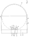
- Figure 1 the output area of a printer 10, e.g. a laser printer shown with the exit rollers 12, which eject the printed sheets 14 and place them in a stack 16 in a stack.
- the printer 10 is commercially available, is not the subject of the invention and therefore need not be described further.
- the device according to the invention is placed above the exit rollers 12 on the upper cover plate of the printer 10.
- the device has a housing 18, which is seated on the cover plate of the printer 10 and which is fastened to the printer 10, for example, with brackets 20 encompassing the cover plate.
- a magazine 22 is formed at the top of the housing 18, in which separating foils 24 are inserted in a stack.
- the separating foils 24 are circular disks which are made of a suitable plastic and are of such a strength that they have a certain inherent stiffness, but can be bent under slight pressure.
- the diameter of the separating foils 24 is larger than the width of the sheets 14.
- the magazine 22 is formed from a support surface 26, which is formed on the top of the housing 18 and extends from the housing 18 to the rear at an incline.
- Guide cheeks 28 projecting vertically upward are formed on the two side edges of the support surface 26.
- the width of the support surface 26, ie the clear distance between the guide cheeks 28 corresponds to the diameter of the separating foils 24, while the length of the supporting surface 26 is at least greater than the radius, preferably equal to the diameter of the separating foils 24.
- the separating foils 24 can thus be placed loosely stacked on top of one another in the magazine 22, wherein they are supported by the support surface 26 and guided laterally by the guide cheeks 28.
- a vertical stop wall 30 of the housing 18 is arranged, which on the inclined support surface 26 supports stack of separating foils 24 sliding forward.
- a horizontal shaft 32 running parallel to the stop wall 30 is rotatably mounted in the housing 18.
- Two separating rollers 34 are seated on the shaft 32 in a rotationally fixed manner, and their adhesive circumference engages through openings 36 of the front edge of the support surface 26 adjoining the stop wall 30.
- the circumference of the singling rollers 34 protrudes slightly above the surface of the support surface 26.
- the shaft 32 with the separating rollers 34 can be driven by a lower one of the bearing surface 26 in the housing 18, an electric motor 38 via a worm gear 40. In the illustration in FIG. 1, the singling rollers 34 are driven counterclockwise.
- a passage channel 42 opens, which extends over the entire width of the support surface 26, the height of which is greater than the single thickness and less than twice the thickness of the separating films and which is flush with the top of the support surface 26 connects.
- the passage channel 42 begins at the angle of inclination of the support surface 26 and extends, with a slight curvature into the horizontal, essentially horizontally through the housing 18.
- the outlet end of the passage channel 42 opens at the vertical front side of the housing 18, which extends over the edge of the roller covering the outlet rollers 12 top cover plate of the printer 10 is located.
- two lower ejection rollers 44 are arranged in the center on a shaft 46.
- the shaft 46, and thus the lower ejection rollers 44, are driven by the shaft 32, and thus by the electric motor 38, via a gear transmission 48.
- the direction of rotation of the drive of the lower ejection rollers 44 is the same as the direction of rotation of the separating rollers 34, ie in the illustration of the figure 1 counterclockwise.
- upper ejection rollers 50 are freely rotatably mounted in the housing 18 and are seated on the lower ejection rollers 44 from above.
- the printed sheets 14 are ejected via the exit rollers 12 and placed in a stack in the tray 16. If a coherent printing process (printing job) has been completed and the group of sheets 14 belonging to this process is stacked in the tray 16, the device receives a start signal which sets the electric motor 38 in operation.
- the electric motor 38 drives the separating rollers 34 and the lower ejection rollers 44.
- the separating rollers 34 frictionally engage the bottom separating film 24 of the separating films stacked in the magazine 22 from below and push them through the passage channel 42. Since the height of the passing channel 42 is less than twice the thickness of the separating films 24, only one separating film 24 can pass through the passage channel 42 are pushed.
- the separating film 24 comes between the lower ejection rollers 44 and the upper ejection rollers 50 and is grasped by them and transported by the lower ejection rollers 44 by friction, as indicated by the broken line in FIG. As soon as the separating film 24 has completely passed the ejection rollers 44 and 50, the separating film 24 falls down freely and lies on the stack of sheets 14. The electric motor 38 is then stopped again. Printer 10 can now begin the next printing process. After this subsequent printing process has been completed, the next release film 24 is placed in a corresponding manner. Because of their larger diameter, the separating foils 24 inserted into the stack of sheets 14 deposited in the tray 16 protrude beyond the edge of the stack, as shown in FIG. 1.
- the protruding edge of the separating foils 24 can be easily grasped in order to raise the respective separating foil 24 and the part of the entire sheet stack lying above it. As a result, the sheets 14 lying under the raised separating film 24 can be viewed.
- a desired sheet group can be made in any position be removed from the stack. It is only necessary to lift the corresponding separating film 24 and the desired group of sheets can be removed together with the associated separating film 24.
- the release films 24 which are no longer required after removal from the tray 16 are simply placed back into the magazine 22 at the top of the stack of release films 24 stored there. Due to the lateral guide cheeks 28 and the inclination of the support surface 26, the separating foils 24 inserted into the magazine 22 are inevitably stacked congruently. Because of the circular shape of the separating foils 24, a separate alignment is not necessary.
Landscapes
- Sheets, Magazines, And Separation Thereof (AREA)
- Paper Feeding For Electrophotography (AREA)
- Forming Counted Batches (AREA)
- Pile Receivers (AREA)
Applications Claiming Priority (2)
| Application Number | Priority Date | Filing Date | Title |
|---|---|---|---|
| DE19619995A DE19619995C1 (de) | 1996-05-17 | 1996-05-17 | Vorrichtung zur trennbar gestapelten Ablage von Blättern |
| DE19619995 | 1996-05-17 |
Publications (3)
| Publication Number | Publication Date |
|---|---|
| EP0807594A2 true EP0807594A2 (fr) | 1997-11-19 |
| EP0807594A3 EP0807594A3 (fr) | 1998-06-10 |
| EP0807594B1 EP0807594B1 (fr) | 2002-03-20 |
Family
ID=7794623
Family Applications (1)
| Application Number | Title | Priority Date | Filing Date |
|---|---|---|---|
| EP97107901A Expired - Lifetime EP0807594B1 (fr) | 1996-05-17 | 1997-05-15 | Dispositif pour le dépôt de feuilles en piles séparables |
Country Status (4)
| Country | Link |
|---|---|
| US (1) | US6089559A (fr) |
| EP (1) | EP0807594B1 (fr) |
| JP (1) | JPH1081442A (fr) |
| DE (2) | DE19619995C1 (fr) |
Families Citing this family (5)
| Publication number | Priority date | Publication date | Assignee | Title |
|---|---|---|---|---|
| DE19640657C2 (de) * | 1996-10-02 | 1998-11-05 | Patentia Hergiswil Ag | Verfahren und Vorrichtung zum Trennen von gestapelt abgelegten Blättern |
| US6227531B1 (en) * | 1999-05-25 | 2001-05-08 | Hewlett-Packard Company | Job separation process, system and method for distributing print jobs |
| JP4095412B2 (ja) * | 2002-11-22 | 2008-06-04 | キヤノン株式会社 | 画像形成装置及び画像形成方法 |
| DE102008007107A1 (de) * | 2008-01-31 | 2009-08-13 | Zf Friedrichshafen Ag | Axialkugelgelenk mit Anschlagdämpfung |
| US20110149335A1 (en) * | 2009-12-17 | 2011-06-23 | International Business Machines Corporation | Printing a plurality of electronic documents on a computer printer, where the printer is logically coupled to a plurality of computer systems |
Family Cites Families (15)
| Publication number | Priority date | Publication date | Assignee | Title |
|---|---|---|---|---|
| US3458186A (en) * | 1966-09-08 | 1969-07-29 | Leipzig Veb Druckmasch Werke | Device for insertion of marking strips into a forming stack |
| US3838851A (en) * | 1972-02-22 | 1974-10-01 | Addressograph Multigraph | Bottom sheet feeder |
| US3794550A (en) * | 1972-08-25 | 1974-02-26 | Standard Oil Co | Sheet binding |
| CH647735A5 (de) * | 1980-07-15 | 1985-02-15 | Grapha Holding Ag | Verfahren zur herstellung von stapeln aus gefalzten druckbogen und vorrichtung zur durchfuehrung des verfahrens. |
| JPS59203060A (ja) * | 1983-04-27 | 1984-11-17 | Ricoh Co Ltd | 複写装置 |
| JPS624172A (ja) * | 1985-06-26 | 1987-01-10 | Canon Inc | 用紙の区分積載方法 |
| US4624452A (en) * | 1985-08-19 | 1986-11-25 | Pulskamp Nicholas R | Board inserter for printing press |
| JPS62167170A (ja) * | 1986-01-17 | 1987-07-23 | Fuji Xerox Co Ltd | 複写装置における排出用紙の仕分け方法 |
| JPS62185675A (ja) * | 1986-02-07 | 1987-08-14 | Canon Inc | 記録装置 |
| US4784508A (en) * | 1986-10-10 | 1988-11-15 | Shannon Brian M | Tabular divider sheets |
| US5020786A (en) * | 1988-08-31 | 1991-06-04 | Kanzaki Paper Manufacturing Co., Ltd. | Paper inserting apparatus |
| JPH03166164A (ja) * | 1989-11-24 | 1991-07-18 | Konica Corp | カラー画像形成装置 |
| US5272511A (en) * | 1992-04-30 | 1993-12-21 | Xerox Corporation | Sheet inserter and methods of inserting sheets into a continuous stream of sheets |
| US5316279A (en) * | 1993-01-04 | 1994-05-31 | Xerox Corporation | Copier/printer job stacking with discrete cover sheets with extending printed banners |
| US5709374A (en) * | 1996-10-18 | 1998-01-20 | Xerox Corporation | System for automatic print jobs separations in container with vertically projecting folders |
-
1996
- 1996-05-17 DE DE19619995A patent/DE19619995C1/de not_active Expired - Fee Related
-
1997
- 1997-05-14 US US08/856,367 patent/US6089559A/en not_active Expired - Fee Related
- 1997-05-15 EP EP97107901A patent/EP0807594B1/fr not_active Expired - Lifetime
- 1997-05-15 DE DE59706646T patent/DE59706646D1/de not_active Expired - Fee Related
- 1997-05-16 JP JP9127121A patent/JPH1081442A/ja active Pending
Also Published As
| Publication number | Publication date |
|---|---|
| US6089559A (en) | 2000-07-18 |
| DE19619995C1 (de) | 1998-01-29 |
| EP0807594B1 (fr) | 2002-03-20 |
| EP0807594A3 (fr) | 1998-06-10 |
| JPH1081442A (ja) | 1998-03-31 |
| DE59706646D1 (de) | 2002-04-25 |
Similar Documents
| Publication | Publication Date | Title |
|---|---|---|
| DE69216881T2 (de) | Blattnachbearbeitungsvorrichtung | |
| DE2905171C2 (de) | Vorrichtung zum Zuführen von Einzelblättern aus einem Magazin zur Schreibwalze einer schreibenden Büro- oder Datenverarbeitungsmaschine und zum Ablegen der von der Schreibwalze kommenden Einzelblätter | |
| DE3311419C2 (fr) | ||
| DE69312139T2 (de) | Vorrichtung zum Zuführen von flachen, hochkantgestellten Gegenständen an den Entstapelkopf eines automatischen Sortiersystems | |
| DE2363558C2 (de) | Vorrichtung zum Zusammenstellen oder Verteilen von Blättern | |
| EP0449010B1 (fr) | Appareil de triage pour dépôt de porte-notes sous forme de feuilles | |
| DE69201833T2 (de) | Herausnehmbarer zuführkorb mit zwei fächern für umschläge für eine maschine zur reproduktion von abbildungen wie schnelldrucker oder kopiergerät. | |
| DE2742447A1 (de) | Vorrichtung und verfahren zum transportieren und ablegen von zickzackfoermig gefalteten papierbahnen | |
| DE19806029C1 (de) | Vorrichtung zur Entnahme von Banknotenbündeln und Bereitstellung an einer Entnahmestelle | |
| DE10147134B4 (de) | Stackerriemen mit geschalteten Einzahlkassetten | |
| EP0839747B1 (fr) | Méthode et dispositif pour déposer des feuilles en piles séparables | |
| DE19619995C1 (de) | Vorrichtung zur trennbar gestapelten Ablage von Blättern | |
| DE69710016T2 (de) | Vorrichtung zum Sammeln und zur gerichteten Orientierung von Bögen | |
| DE60007910T2 (de) | Blattzuführvorrichtung | |
| DE3943136C2 (fr) | ||
| DE3808661A1 (de) | Ablageeinrichtung zum abstapeln blattfoermiger aufzeichnungstraeger in einem ausgabefach einer druckeinrichtung | |
| DE19619991C2 (de) | Vorrichtung zur trennbar gestapelten Ablage von Blättern | |
| DE2840430C2 (de) | Vorrichtung zur Ausgabe flacher Gegenstände | |
| DE19750592C2 (de) | Vorrichtung zur Ablage von Blättern, die von einer Büromaschine ausgegeben werden | |
| DE3031869C2 (de) | Vorrichtung zum Zuführen von Einzelblättern zur Schreibstation einer schreibenden Büro- oder Datenverarbeitungsmaschine und zum Ablegen der von der Schreibstation kommenden Einzelblätter | |
| DE69606824T2 (de) | Drucker mit Verteilungsstationen | |
| EP0169426B1 (fr) | Dispositif de dépôt du papier pour imprimantes à jet d'encre | |
| EP1440923B1 (fr) | Agencement et procédé pour l'empilage sélectif de rames de tailles et/ou de formes différentes | |
| CH667633A5 (de) | Vorrichtung fuer die zufuhr insbesondere von briefumschlaegen zur schreibwalze einer bueromaschine. | |
| DE3037440C2 (de) | Vorrichtung zum Zuführen von Einzelblättern, insbesondere Kuverts, zur Schreibwalze einer schreibenden Büromaschine |
Legal Events
| Date | Code | Title | Description |
|---|---|---|---|
| PUAI | Public reference made under article 153(3) epc to a published international application that has entered the european phase |
Free format text: ORIGINAL CODE: 0009012 |
|
| AK | Designated contracting states |
Kind code of ref document: A2 Designated state(s): DE FR GB IT |
|
| K1C1 | Correction of patent application (title page) published |
Effective date: 19971119 |
|
| PUAL | Search report despatched |
Free format text: ORIGINAL CODE: 0009013 |
|
| AK | Designated contracting states |
Kind code of ref document: A3 Designated state(s): DE FR GB IT |
|
| 17P | Request for examination filed |
Effective date: 19980629 |
|
| 17Q | First examination report despatched |
Effective date: 20000907 |
|
| RIC1 | Information provided on ipc code assigned before grant |
Free format text: 7B 65H 33/04 A |
|
| RTI1 | Title (correction) |
Free format text: DEVICE FOR DEPOSITING SHEETS IN SEPARABLE PILES |
|
| GRAG | Despatch of communication of intention to grant |
Free format text: ORIGINAL CODE: EPIDOS AGRA |
|
| GRAG | Despatch of communication of intention to grant |
Free format text: ORIGINAL CODE: EPIDOS AGRA |
|
| GRAH | Despatch of communication of intention to grant a patent |
Free format text: ORIGINAL CODE: EPIDOS IGRA |
|
| GRAH | Despatch of communication of intention to grant a patent |
Free format text: ORIGINAL CODE: EPIDOS IGRA |
|
| REG | Reference to a national code |
Ref country code: GB Ref legal event code: IF02 |
|
| GRAA | (expected) grant |
Free format text: ORIGINAL CODE: 0009210 |
|
| AK | Designated contracting states |
Kind code of ref document: B1 Designated state(s): DE FR GB IT |
|
| PG25 | Lapsed in a contracting state [announced via postgrant information from national office to epo] |
Ref country code: IT Free format text: LAPSE BECAUSE OF FAILURE TO SUBMIT A TRANSLATION OF THE DESCRIPTION OR TO PAY THE FEE WITHIN THE PRE;WARNING: LAPSES OF ITALIAN PATENTS WITH EFFECTIVE DATE BEFORE 2007 MAY HAVE OCCURRED AT ANY TIME BEFORE 2007. THE CORRECT EFFECTIVE DATE MAY BE DIFFERENT FROM THE ONE RECORDED.SCRIBED TIME-LIMIT Effective date: 20020320 Ref country code: GB Free format text: LAPSE BECAUSE OF FAILURE TO SUBMIT A TRANSLATION OF THE DESCRIPTION OR TO PAY THE FEE WITHIN THE PRESCRIBED TIME-LIMIT Effective date: 20020320 Ref country code: FR Free format text: LAPSE BECAUSE OF FAILURE TO SUBMIT A TRANSLATION OF THE DESCRIPTION OR TO PAY THE FEE WITHIN THE PRESCRIBED TIME-LIMIT Effective date: 20020320 |
|
| REF | Corresponds to: |
Ref document number: 59706646 Country of ref document: DE Date of ref document: 20020425 |
|
| GBV | Gb: ep patent (uk) treated as always having been void in accordance with gb section 77(7)/1977 [no translation filed] |
Effective date: 20020320 |
|
| EN | Fr: translation not filed | ||
| PLBE | No opposition filed within time limit |
Free format text: ORIGINAL CODE: 0009261 |
|
| STAA | Information on the status of an ep patent application or granted ep patent |
Free format text: STATUS: NO OPPOSITION FILED WITHIN TIME LIMIT |
|
| 26N | No opposition filed |
Effective date: 20021223 |
|
| PGFP | Annual fee paid to national office [announced via postgrant information from national office to epo] |
Ref country code: DE Payment date: 20080626 Year of fee payment: 12 |
|
| PG25 | Lapsed in a contracting state [announced via postgrant information from national office to epo] |
Ref country code: DE Free format text: LAPSE BECAUSE OF NON-PAYMENT OF DUE FEES Effective date: 20091201 |