EP0807594A2 - Method and device for depositing sheets in separable piles - Google Patents
Method and device for depositing sheets in separable piles Download PDFInfo
- Publication number
- EP0807594A2 EP0807594A2 EP97107901A EP97107901A EP0807594A2 EP 0807594 A2 EP0807594 A2 EP 0807594A2 EP 97107901 A EP97107901 A EP 97107901A EP 97107901 A EP97107901 A EP 97107901A EP 0807594 A2 EP0807594 A2 EP 0807594A2
- Authority
- EP
- European Patent Office
- Prior art keywords
- separating
- sheets
- magazine
- foils
- office machine
- Prior art date
- Legal status (The legal status is an assumption and is not a legal conclusion. Google has not performed a legal analysis and makes no representation as to the accuracy of the status listed.)
- Granted
Links
Images

Classifications
-
- B—PERFORMING OPERATIONS; TRANSPORTING
- B65—CONVEYING; PACKING; STORING; HANDLING THIN OR FILAMENTARY MATERIAL
- B65H—HANDLING THIN OR FILAMENTARY MATERIAL, e.g. SHEETS, WEBS, CABLES
- B65H33/00—Forming counted batches in delivery pile or stream of articles
- B65H33/04—Forming counted batches in delivery pile or stream of articles by inserting marker slips in pile or stream
-
- B—PERFORMING OPERATIONS; TRANSPORTING
- B65—CONVEYING; PACKING; STORING; HANDLING THIN OR FILAMENTARY MATERIAL
- B65H—HANDLING THIN OR FILAMENTARY MATERIAL, e.g. SHEETS, WEBS, CABLES
- B65H2701/00—Handled material; Storage means
- B65H2701/10—Handled articles or webs
- B65H2701/17—Nature of material
- B65H2701/176—Cardboard
Definitions
- the invention relates to a method and an apparatus for separably stacked storage of sheets, which are issued by an office machine, according to the preamble of claims 1 and 2 respectively.
- the sheets printed or otherwise provided with records by the office machine are stored in a stack. If sheets, which belong to different processes, are successively deposited on the stack, the sheet groups belonging to the individual processes have to be carefully selected from the stack. This is the case, for example, if several screen workstations are connected to a common central printer.
- the invention has for its object to provide a method and an apparatus which allows a convenient separation of the sheets stored by an office machine stacked sheets with little effort.
- the basic idea of the invention is to attach an additional magazine for the separating foils to the office machine, from which the separating foils are ejected individually and placed on the sheet stack emitted by the office machine. Since the magazine for the separating films is arranged separately on the office machine, the dimensions of the separating film can be selected independently of the sheet transport and the sheet format of the office machine. The dimensions of the separating film are chosen so that they are at least one dimension larger than the sheets issued by the office machine. The separating films therefore protrude from the edge of the sheet stack.
- the separating foils can be easily grasped in this way and the sheet stack can be separated in a convenient manner by lifting the separating foils with the stack lying thereon. By means of the separating foils, the entire stack can be leafed through in groups, so to speak, in order to find the desired group of sheets.
- a sheet group lying somewhere in the stack If a sheet group lying somewhere in the stack is required, it can easily be pulled out of the entire stack together with the associated separating film. The remaining separating foils remain in the stack and continue to separate the successive remaining groups. The release film removed from the stack with the selected sheet group can be reinserted into the magazine so that it is available for further use. It is also advantageous that the entire stack, together with the separating foils, is removed from the storage of the office machine and sent to the place of further processing, e.g. to a work table. There, the different groups of sheets can be separated and stapled, distributed, enveloped or inserted in signature folders, etc. The separating foils are then brought back to the office machine and placed in the magazine.
- the insertion of the separating foils in the deposited sheet stack has the further advantage that the entire for the sheet storage Available space can be used.
- the device is extremely simple, since it only requires a magazine, in which the separating foils are loosely inserted, and a simple output unit, which occasionally releases the separating foils from the magazine.
- the separating foils can be inserted from the magazine into the paper path of the office machine, so that they reach the sheet tray via the sheet output of the office machine.
- the device is preferably arranged above the sheet outlet of the office machine, so that the separating films which are issued are placed on the sheet stack from above without additional guide devices.
- the device can in particular also be designed as a simple additional device, which can optionally be attached to the office machine.
- the magazine must be designed in such a way that the removed separating foils can be easily and conveniently replaced in the magazine.
- the magazine expediently has an upwardly open receptacle into which the separating foils are inserted.
- the separating foils can have different shapes, their dimensions in relation to the sheets processed by the office machine being selected such that the separating foils reliably protrude from the stack of sheets deposited in the sheet deposit of the office machine. It is expedient for the separating films to have rounded corners which are less at risk of damage when the separating films are used several times.
- the separating films are designed as circular or oval disks, the diameter of which is somewhat larger than the narrow side of the sheets output from the office machine.
- the circular shape of the separating films has the advantage that the separating film can be put back into the magazine of the device after use without any orientation or alignment in the magazine being necessary.
- the release films can be made of any suitable material, e.g. from a paper of suitable stiffness, from thin cardboard or from plastic.
- the release films only have to meet a few basic requirements.
- the stiffness of the separating foils must be sufficient so that they protrude beyond the edge of the stack and so that the stack can be raised by means of the separating foils in order to leaf through the stack.
- the separating films must have sufficient flexibility in order to enable simple separation and removal from the magazine and in order not to hinder the bending of the stack when leafing through.
- the separating foils are expediently transparent in order to be able to easily identify the document lying under the separating foil.
- the separating foils can be better recognized in the stack, the separating foils or at least their edge region protruding from the stack can be colored. Since the separating foils can be used for a long time and the user sees them frequently and daily, the separating foils are also particularly suitable for printing with information or advertising.
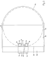
- Figure 1 the output area of a printer 10, e.g. a laser printer shown with the exit rollers 12, which eject the printed sheets 14 and place them in a stack 16 in a stack.
- the printer 10 is commercially available, is not the subject of the invention and therefore need not be described further.
- the device according to the invention is placed above the exit rollers 12 on the upper cover plate of the printer 10.
- the device has a housing 18, which is seated on the cover plate of the printer 10 and which is fastened to the printer 10, for example, with brackets 20 encompassing the cover plate.
- a magazine 22 is formed at the top of the housing 18, in which separating foils 24 are inserted in a stack.
- the separating foils 24 are circular disks which are made of a suitable plastic and are of such a strength that they have a certain inherent stiffness, but can be bent under slight pressure.
- the diameter of the separating foils 24 is larger than the width of the sheets 14.
- the magazine 22 is formed from a support surface 26, which is formed on the top of the housing 18 and extends from the housing 18 to the rear at an incline.
- Guide cheeks 28 projecting vertically upward are formed on the two side edges of the support surface 26.
- the width of the support surface 26, ie the clear distance between the guide cheeks 28 corresponds to the diameter of the separating foils 24, while the length of the supporting surface 26 is at least greater than the radius, preferably equal to the diameter of the separating foils 24.
- the separating foils 24 can thus be placed loosely stacked on top of one another in the magazine 22, wherein they are supported by the support surface 26 and guided laterally by the guide cheeks 28.
- a vertical stop wall 30 of the housing 18 is arranged, which on the inclined support surface 26 supports stack of separating foils 24 sliding forward.
- a horizontal shaft 32 running parallel to the stop wall 30 is rotatably mounted in the housing 18.
- Two separating rollers 34 are seated on the shaft 32 in a rotationally fixed manner, and their adhesive circumference engages through openings 36 of the front edge of the support surface 26 adjoining the stop wall 30.
- the circumference of the singling rollers 34 protrudes slightly above the surface of the support surface 26.
- the shaft 32 with the separating rollers 34 can be driven by a lower one of the bearing surface 26 in the housing 18, an electric motor 38 via a worm gear 40. In the illustration in FIG. 1, the singling rollers 34 are driven counterclockwise.
- a passage channel 42 opens, which extends over the entire width of the support surface 26, the height of which is greater than the single thickness and less than twice the thickness of the separating films and which is flush with the top of the support surface 26 connects.
- the passage channel 42 begins at the angle of inclination of the support surface 26 and extends, with a slight curvature into the horizontal, essentially horizontally through the housing 18.
- the outlet end of the passage channel 42 opens at the vertical front side of the housing 18, which extends over the edge of the roller covering the outlet rollers 12 top cover plate of the printer 10 is located.
- two lower ejection rollers 44 are arranged in the center on a shaft 46.
- the shaft 46, and thus the lower ejection rollers 44, are driven by the shaft 32, and thus by the electric motor 38, via a gear transmission 48.
- the direction of rotation of the drive of the lower ejection rollers 44 is the same as the direction of rotation of the separating rollers 34, ie in the illustration of the figure 1 counterclockwise.
- upper ejection rollers 50 are freely rotatably mounted in the housing 18 and are seated on the lower ejection rollers 44 from above.
- the printed sheets 14 are ejected via the exit rollers 12 and placed in a stack in the tray 16. If a coherent printing process (printing job) has been completed and the group of sheets 14 belonging to this process is stacked in the tray 16, the device receives a start signal which sets the electric motor 38 in operation.
- the electric motor 38 drives the separating rollers 34 and the lower ejection rollers 44.
- the separating rollers 34 frictionally engage the bottom separating film 24 of the separating films stacked in the magazine 22 from below and push them through the passage channel 42. Since the height of the passing channel 42 is less than twice the thickness of the separating films 24, only one separating film 24 can pass through the passage channel 42 are pushed.
- the separating film 24 comes between the lower ejection rollers 44 and the upper ejection rollers 50 and is grasped by them and transported by the lower ejection rollers 44 by friction, as indicated by the broken line in FIG. As soon as the separating film 24 has completely passed the ejection rollers 44 and 50, the separating film 24 falls down freely and lies on the stack of sheets 14. The electric motor 38 is then stopped again. Printer 10 can now begin the next printing process. After this subsequent printing process has been completed, the next release film 24 is placed in a corresponding manner. Because of their larger diameter, the separating foils 24 inserted into the stack of sheets 14 deposited in the tray 16 protrude beyond the edge of the stack, as shown in FIG. 1.
- the protruding edge of the separating foils 24 can be easily grasped in order to raise the respective separating foil 24 and the part of the entire sheet stack lying above it. As a result, the sheets 14 lying under the raised separating film 24 can be viewed.
- a desired sheet group can be made in any position be removed from the stack. It is only necessary to lift the corresponding separating film 24 and the desired group of sheets can be removed together with the associated separating film 24.
- the release films 24 which are no longer required after removal from the tray 16 are simply placed back into the magazine 22 at the top of the stack of release films 24 stored there. Due to the lateral guide cheeks 28 and the inclination of the support surface 26, the separating foils 24 inserted into the magazine 22 are inevitably stacked congruently. Because of the circular shape of the separating foils 24, a separate alignment is not necessary.
Abstract
Description
Die Erfindung betrifft ein Verfahren und eine Vorrichtung zur trennbar gestapelten Ablage von Blättern, die von einer Büromaschine ausgegeben werden, gemäß dem Oberbegriff der Ansprüche 1 bzw. 2.2. The invention relates to a method and an apparatus for separably stacked storage of sheets, which are issued by an office machine, according to the preamble of claims 1 and 2 respectively.
Bei zahlreichen Büromaschinen, wie Druckern, Telekopierern, Kopiergeräten usw. werden die von der Büromaschine bedruckten oder in sonstiger Weise mit Aufzeichnungen versehenen Blätter gestapelt abgelegt. Werden aufeinanderfolgend Blätter auf den Stapel abgelegt, die zu unterschiedlichen Vorgängen gehören, so müssen die zu den einzelnen Vorgängen gehörenden Blattgruppen mühsam aus dem Stapel herausgesucht werden. Dies ist beispielsweise der Fall, wenn mehrere Bildschirm-Arbeitsplätze an einen gemeinsamen zentralen Drucker angeschlossen sind.With numerous office machines, such as printers, facsimiles, copiers, etc., the sheets printed or otherwise provided with records by the office machine are stored in a stack. If sheets, which belong to different processes, are successively deposited on the stack, the sheet groups belonging to the individual processes have to be carefully selected from the stack. This is the case, for example, if several screen workstations are connected to a common central printer.
Es ist bekannt, dem Blattaustritt einer Büromaschine einen Sorter nachzuordnen, der eine Vielzahl von Ablagefächern aufweist, so daß die zu unterschiedlichen Vorgängen gehörenden Blätter gesteuert jeweils in gesonderte Ablagefächer gelangen. Ein solcher Sorter ist aufwendig, beansprucht viel Platz und die Zahl der zur Verfügung stehenden Ablagefächer und deren Aufnahmekapazität ist begrenzt. Wird der Inhalt mehrerer Ablagefächer gemeinsam entnommen und an einen Arbeitsplatz zur Weiterverarbeitung gebracht, so werden in der Regel die in dem Sorter getrennten Stapel wieder vereinigt und müssen am Arbeitsplatz erneut getrennt werden.It is known to assign a sorter to the sheet exit of an office machine, which sorter has a plurality of storage compartments, so that the sheets belonging to different processes each arrive in separate storage compartments under control. Such a sorter is complex, takes up a lot of space and the number of storage compartments available and their storage capacity is limited. If the contents of several storage compartments are removed together and brought to a work station for further processing, the contents of the Sorter separated stacks reunited and must be separated again at the workplace.
Weiter ist es bekannt, zwischen die Blattgruppen, die zu verschiedenen Vorgängen gehören, Papierblätter zu legen, die sich farblich von den Blättern des Stapels unterscheiden. Werden diese Trennblätter in einer der Kassetten bereit gehalten, die in den Büromaschinen für die zu bedruckenden Blätter vorgesehen sind, so ist ein automatisches Einlegen der Trennblätter möglich, die Trennblätter beanspruchen jedoch eines der Magazine der Büromaschine, die nur in begrenzter Anzahl zur Verfügung stehen. Zudem weisen die Trennblätter das gleiche Format auf wie die abzulegenden Blätter, so daß das Trennen des Stapels mittels der Trennblätter mühsam ist. Eine Wiederverwendung der Trennblätter ist kaum möglich, da sie der Hitzeeinwirkung im Drucker bzw. Kopierer ausgesetzt werden.It is also known to place sheets of paper that differ in color from the sheets of the stack between the sheet groups that belong to different processes. If these separator sheets are kept ready in one of the cassettes which are provided in the office machines for the sheets to be printed, then an automatic insertion of the separator sheets is possible, but the separator sheets claim one of the magazines of the office machine, which are only available in limited numbers. In addition, the separator sheets have the same format as the sheets to be deposited, so that the separation of the stack by means of the separator sheets is tedious. It is hardly possible to reuse the separator sheets as they are exposed to the heat in the printer or copier.
Schließlich ist es bekannt, die jeweils aufeinanderfolgenden, zu verschiedenen Vorgängen gehörenden Blattgruppen, gegeneinander versetzt abzulegen (Offset-Ablage). Durch die gegeneinander versetzte Ablage können die einzelnen Blattgruppen des Stapels leicht getrennt werden. Wird jedoch bei Bedarf die zu einem Vorgang gehörende Blattgruppe aus dem Stapel entnommen, so liegen anschließend zwei Blattgruppen aufeinander, die nicht gegeneinander versetzt sind und daher nicht mehr erkennbar getrennt werden können.Finally, it is known to store the successive sheet groups belonging to different processes offset from one another (offset storage). The staggered stack makes it easy to separate the individual groups of sheets in the stack. If, however, the sheet group belonging to an operation is removed from the stack as required, then two sheet groups lie one on top of the other, which are not offset from one another and can therefore no longer be separated.
Der Erfindung liegt die Aufgabe zugrunde, ein Verfahren und eine Vorrichtung zu schaffen, die mit geringem Aufwand ein bequemes Trennen der von einer Büromaschine gestapelt abgelegten Blätter ermöglicht.The invention has for its object to provide a method and an apparatus which allows a convenient separation of the sheets stored by an office machine stacked sheets with little effort.
Diese Aufgabe wird erfindungsgemäß gelöst ein Verfahren mit den Merkmalen des Anspruchs 1 bzw. durch eine Vorrichtung mit den Merkmalen des Anspruchs 2.This object is achieved according to the invention by a method having the features of claim 1 or by an apparatus having the features of claim 2.
Vorteilhafte Ausführungen der Erfindung sind in den Unteransprüchen angegeben.Advantageous embodiments of the invention are specified in the subclaims.
Der Grundgedanke der Erfindung besteht darin, an der Büromaschine ein zusätzliches Magazin für die Trennfolien anzubringen, von welchem die Trennfolien vereinzelt ausgegeben und auf den von der Büromaschine ausgegebenen Blattstapel abgelegt werden. Da das Magazin für die Trennfolien gesondert an der Büromaschine angeordnet ist, können die Abmessungen der Trennfolie unabhängig von dem Blatt-Transport und dem Blattformat der Büromaschine gewählt werden. Die Abmessungen der Trennfolie sind so gewählt, daß sie zumindest in einer Dimension größer als die von der Büromaschine ausgegebenen Blätter sind. Die Trennfolien ragen daher aus dem Rand des Blattstapels heraus. Die Trennfolien können auf diese Weise leicht erfaßt werden und ein Trennen des Blattstapels ist in bequemer Weise möglich, indem die Trennfolien mit dem daraufliegenden Stapel angehoben werden. Mittels der Trennfolien kann der gesamte Stapel blattgruppenweise gewissermaßen durchgeblättert werden, um die gewünschte Blattgruppe herauszusuchen.The basic idea of the invention is to attach an additional magazine for the separating foils to the office machine, from which the separating foils are ejected individually and placed on the sheet stack emitted by the office machine. Since the magazine for the separating films is arranged separately on the office machine, the dimensions of the separating film can be selected independently of the sheet transport and the sheet format of the office machine. The dimensions of the separating film are chosen so that they are at least one dimension larger than the sheets issued by the office machine. The separating films therefore protrude from the edge of the sheet stack. The separating foils can be easily grasped in this way and the sheet stack can be separated in a convenient manner by lifting the separating foils with the stack lying thereon. By means of the separating foils, the entire stack can be leafed through in groups, so to speak, in order to find the desired group of sheets.
Wird eine irgendwo in dem Stapel liegende Blattgruppe benötigt, so kann diese problemlos zusammen mit der zugehörigen Trennfolie aus dem gesamten Stapel herausgezogen werden. Die übrigen Trennfolien bleiben in dem Stapel und trennen weiterhin die aufeinanderfolgenden verbleibenden Gruppen. Die mit der ausgewählten Blattgruppe aus dem Stapel entnommene Trennfolie kann wieder in das Magazin eingelegt werden, so daß sie für die weitere Verwendung zur Verfügung steht. Vorteilhaft ist auch, daß der gesamte Stapel zusammen mit den Trennfolien aus der Ablage der Büromaschine entnommen und an den Ort der Weiterverarbeitung, z.B. an einen Arbeitstisch, gebracht werden kann. Dort können die unterschiedlichen Blattgruppen getrennt und geheftet, verteilt, kuvertiert oder in Unterschriftmappen usw. eingelegt werden. Die Trennfolien werden anschließend wieder zu der Büromaschine zurückgebracht und in das Magazin eingelegt.If a sheet group lying somewhere in the stack is required, it can easily be pulled out of the entire stack together with the associated separating film. The remaining separating foils remain in the stack and continue to separate the successive remaining groups. The release film removed from the stack with the selected sheet group can be reinserted into the magazine so that it is available for further use. It is also advantageous that the entire stack, together with the separating foils, is removed from the storage of the office machine and sent to the place of further processing, e.g. to a work table. There, the different groups of sheets can be separated and stapled, distributed, enveloped or inserted in signature folders, etc. The separating foils are then brought back to the office machine and placed in the magazine.
Das Einlegen der Trennfolien in den abgelegten Blattstapel hat weiter den Vorteil, daß der gesamte für die Blattablage zur Verfügung stehende Raum ausgenützt werden kann. Die nur durch die Trennfolien voneinander getrennten unterschiedlichen Blattgruppen liegen dicht aufeinander und nehmen nur den Platz in Anspruch, der tatsächlich benötigt wird. Ungenutzter Zwischenraum, wie er bei Sortern durch unvollständig gefüllte Ablagefächer und den für den Einwurf der Blätter in die Fächer benötigten Freiraum bedingt ist, ist nicht vorhanden.The insertion of the separating foils in the deposited sheet stack has the further advantage that the entire for the sheet storage Available space can be used. The different leaf groups, which are only separated from one another by the separating foils, lie close together and only take up the space that is actually needed. There is no unused space, such as is required for sorters due to incompletely filled storage compartments and the space required for the sheets to be inserted into the compartments.
Die Vorrichtung ist äußerst einfach aufgebaut, da sie lediglich ein Magazin benötigt, in welches die Trennfolien lose eingelegt werden, sowie eine einfache Ausgabeeinheit, die die Trennfolien vereinzelt aus dem Magazin abgibt. Die Trennfolien können aus dem Magazin in den Papierpfad der Büromaschine eingeführt werden, so daß sie über die Blattausgabe der Büromaschine in die Blattablage gelangen. Vorzugsweise wird die Vorrichtung jedoch oberhalb des Blattaustrittes der Büromaschine angeordnet, so daß die ausgegebenen Trennfolien ohne zusätzliche Leiteinrichtungen von oben auf den Blattstapel gelegt werden. Die Vorrichtung kann insbesondere auch als einfaches Zusatzgerät gestaltet sein, welches optional an der Büromaschine angebaut werden kann.The device is extremely simple, since it only requires a magazine, in which the separating foils are loosely inserted, and a simple output unit, which occasionally releases the separating foils from the magazine. The separating foils can be inserted from the magazine into the paper path of the office machine, so that they reach the sheet tray via the sheet output of the office machine. However, the device is preferably arranged above the sheet outlet of the office machine, so that the separating films which are issued are placed on the sheet stack from above without additional guide devices. The device can in particular also be designed as a simple additional device, which can optionally be attached to the office machine.
Das Magazin muß so ausgebildet sein, daß die entnommenen Trennfolien leicht und bequem in das Magazin zurückgelegt werden können. Hierzu weist das Magazin zweckmäßig eine nach oben offene Aufnahme auf, in welche die Trennfolen eingelegt werden.The magazine must be designed in such a way that the removed separating foils can be easily and conveniently replaced in the magazine. For this purpose, the magazine expediently has an upwardly open receptacle into which the separating foils are inserted.
Die Trennfolien können unterschiedliche Form aufweisen, wobei ihre Abmessungen in bezug auf die von der Büromaschine verarbeiteten Blätter so gewählt sind, daß die Trennfolien zuverlässig aus dem Stapel der in der Blattablage der Büromaschine abgelegten Blätter herausragen. Es ist zweckmäßig, daß die Trennfolien abgerundete Ecken aufweisen, die bei dem mehrfachen Gebrauch der Trennfolien weniger durch Beschädigungen gefährdet sind. In einer bevorzugten Ausführung sind die Trennfolien als kreisrunde oder ovale Scheiben ausgebildet, deren Durchmesser etwas größer ist, als die Schmalseite der von der Büromaschine ausgegebenen Blätter. Die kreisrunde Form der Trennfolien hat den Vorteil, daß die Trennfolie nach Gebrauch wieder in das Magazin der Vorrichtung zurückgelegt werden können, ohne daß eine Orientierung oder Ausrichtung im Magazin erforderlich ist.The separating foils can have different shapes, their dimensions in relation to the sheets processed by the office machine being selected such that the separating foils reliably protrude from the stack of sheets deposited in the sheet deposit of the office machine. It is expedient for the separating films to have rounded corners which are less at risk of damage when the separating films are used several times. In a preferred embodiment, the separating films are designed as circular or oval disks, the diameter of which is somewhat larger than the narrow side of the sheets output from the office machine. The circular shape of the separating films has the advantage that the separating film can be put back into the magazine of the device after use without any orientation or alignment in the magazine being necessary.
Die Trennfolien können aus jedem geeigneten Werkstoff bestehen, z.B. aus einem Papier geeigneter Steifigkeit, aus dünner Pappe oder aus Kunststoff. Die Trennfolien müssen nur wenige Grundanforderungen erfüllen. Die Steifigkeit der Trennfolien muß ausreichen, damit diese über den Rand des Stapels hinaus ragen und damit ein Anheben des Stapels mittels der Trennfolien zum Durchblättern des Stapels möglich ist. Andererseits müssen die Trennfolien eine ausreichende Biegsamkeit aufweisen, um ein einfaches Vereinzeln und Abziehen aus dem Magazin zu ermöglichen und um das Durchbiegen des Stapels beim Durchblättern nicht zu behindern. Da die Trennfolien mehrfach verwendet werden, sollten sie schließlich eine ausreichende Widerstandsfähigkeit für einen länger dauernden Gebrauch aufweisen. Zweckmäßigerweise sind die Trennfolien transparent, um das jeweils unter der Trennfolie liegende Dokument leicht identifizieren zu können. Damit die Trennfolien im Stapel besser erkennbar sind, können die Trennfolien oder zumindest ihr aus dem Stapel herausragender Randbereich farbig ausgebildet sein. Da die Trennfolien lange Zeit benutzbar sind und dem Benutzer täglich und häufig vor Augen kommen, eignen sich die Trennfolien auch besonders für das Bedrucken mit Informationen oder Werbung.The release films can be made of any suitable material, e.g. from a paper of suitable stiffness, from thin cardboard or from plastic. The release films only have to meet a few basic requirements. The stiffness of the separating foils must be sufficient so that they protrude beyond the edge of the stack and so that the stack can be raised by means of the separating foils in order to leaf through the stack. On the other hand, the separating films must have sufficient flexibility in order to enable simple separation and removal from the magazine and in order not to hinder the bending of the stack when leafing through. Finally, since the separating foils are used several times, they should have sufficient resistance for long-term use. The separating foils are expediently transparent in order to be able to easily identify the document lying under the separating foil. So that the separating foils can be better recognized in the stack, the separating foils or at least their edge region protruding from the stack can be colored. Since the separating foils can be used for a long time and the user sees them frequently and daily, the separating foils are also particularly suitable for printing with information or advertising.
Im folgenden wird die Erfindung anhand eines in der Zeichnung dargestellten Ausführungsbeispiels näher erläutert. Es zeigen
- Figur 1
- einen Vertikalschnitt durch die auf einen Drucker aufgebaute Vorrichtung und
- Figur 2
- eine Draufsicht auf die Vorrichtung.
- Figure 1
- a vertical section through the device built on a printer and
- Figure 2
- a plan view of the device.
In Figur 1 ist der Ausgabebereich eines Druckers 10, z.B. eines Laserdruckers gezeigt mit den Austrittsrollen 12, die die bedruckten Blätter 14 auswerfen und in einer Ablage 16 gestapelt ablegen. Der Drucker 10 ist handelsüblich, nicht Gegenstand der Erfindung und muß daher nicht weiter beschrieben werden.In Figure 1 the output area of a
Die erfindungsgemäße Vorrichtung ist oberhalb der Austrittsrollen 12 auf die obere Abdeckplatte des Druckers 10 aufgesetzt. Die Vorrichtung weist ein auf der Abdeckplatte des Druckers 10 aufsitzendes Gehäuse 18 auf, welches beispeilsweise mit die Abdeckplatte umgreifenden Bügeln 20 an dem Drucker 10 befestigt wird. Oben an dem Gehäuse 18 ist ein Magazin 22 ausgebildet, in welches Trennfolien 24 gestapelt eingelegt werden. Die Trennfolien 24 sind Kreisscheiben, die aus einem geeigneten Kunststoff bestehen und eine solche Stärke aufweisen, daß sie eine gewisse Eigensteifigkeit aufweisen, sich jedoch unter leichtem Druck durchbiegen lassen. Der Durchmesser der Trennfolien 24 ist größer als die Breite der Blätter 14.The device according to the invention is placed above the
Das Magazin 22 ist gebildet aus einer Auflagefläche 26, die an der Oberseite des Gehäuses 18 angeformt ist und sich von dem Gehäuse 18 nach hinten unter einem Neigungswinkel ansteigend erstreckt. An den beiden Seitenkanten der Auflagefläche 26 sind senkrecht nach oben ragende Führungswangen 28 angeformt. Die Breite der Auflagefläche 26, d.h. der lichte Abstand der Führungswangen 28 entspricht dem Durchmesser der Trennfolien 24, während die Länge der Auflagefläche 26 zumindest größer als der Radius vorzugsweise gleich dem Durchmesser der Trennfolien 24 ist. Die Trennfolien 24 können somit aufeinandergestapelt lose in das Magazin 22 eingelegt werden, wobei sie durch die Auflagefläche 26 abgestützt und durch die Führungswangen 28 seitlich geführt sind. An der vorderen unteren Querkante des Magazins 22 ist eine vertikale Anschlagwand 30 des Gehäuses 18 angeordnet, die den auf der geneigten Auflagefläche 26 nach vorn rutschenden Stapel der Trennfolien 24 abstützt.The
Unterhalb des vorderen unteren Randes der Auflagefläche 26 ist eine parallel zur Anschlagwand 30 verlaufende horizontale Welle 32 drehbar in dem Gehäuse 18 gelagert. Auf der Welle 32 sitzen drehfest zwei Vereinzelungsrollen 34, die mit ihrem adhäsiven Umfang durch an die Anschlagwand 30 angrenzende Durchbrüche 36 des vorderen Randes der Auflagefläche 26 hindurchgreifen. Wie aus Figur 1 zu erkennen ist, ragt der Umfang der Vereinzelungsrollen 34 geringfügig über die Oberfläche der Auflagefläche 26 heraus. Die Welle 32 mit den Vereinzelungsrollen 34 ist durch einen unteren der Auflagefläche 26 in dem Gehäuse 18 gelagerten Elektromotor 38 über ein Schneckengetriebe 40 antreibbar. Der Antrieb der Vereinzelungsrollen 34 erfolgt in der Darstellung der Figur 1 im Gegenuhrzeigersinn. An der unteren Querkante der Anschlagwand 30 öffnet sich ein Durchtrittskanal 42, der sich über die gesamte Breite der Auflagefläche 26 erstreckt, dessen Höhe größer als die einfache Stärke und kleiner als die doppelte Stärke der Trennfolien zu ist und der sich bündig an die Oberseite der Auflagefläche 26 anschließt. Der Durchtrittskanal 42 beginnt mit dem Neigungswinkel der Auflagefläche 26 und verläuft unter leichter Krümmung in die Horizontale im wesentlichen waagerecht durch das Gehäuse 18. Das Austrittsende des Durchtrittskanals 42 mündet an der vertikalen Vorderseite des Gehäuses 18, die sich über dem die Austrittsrollen 12 abdeckenden Rand der oberen Deckplatte des Druckers 10 befindet. An der Unterseite des Austrittsendes des Durchtrittskanals 42 sind mittig zwei untere Auswurfrollen 44 auf einer Welle 46 angeordnet. Die Welle 46, und damit die unteren Auswurfrollen 44, werden über ein Zahnradgetriebe 48 von der Welle 32, und damit von dem Elektromotor 38, angetrieben. Der Drehsinn des Antriebs der unteren Auswurfrollen 44 ist der gleiche wie der Drehsinn der Vereinzelungsrollen 34, d.h. in der Darstellung der Figur 1 der Gegenuhrzeigersinn. Oberhalb des Austrittsendes des Durchtrittskanals 42 sind in dem Gehäuse 18 obere Auswurfrollen 50 frei drehbar gelagert, die abgefedert von oben auf den unteren Auswurfrollen 44 aufsitzen.Below the lower front edge of the
Im Betrieb des Druckers 10 werden die bedruckten Blätter 14 über die Austrittsrollen 12 ausgeworfen und gestapelt in der Ablage 16 abgelegt. Ist ein zusammenhängender Druckvorgang (Druckjob) abgeschlossen und ist die zu diesem Vorgang gehörende Gruppe von Blättern 14 gestapelt in der Ablage 16 abgelegt, so erhält die Vorrichtung ein Startsignal, welches den Elektromotor 38 in Betrieb setzt. Der Elektromotor 38 treibt die Vereinzelungsrollen 34 und die unteren Auswurfrollen 44 an. Die Vereinzelungsrollen 34 greifen reibschlüssig von unten an der untersten Trennfolie 24 der in dem Magazin 22 gestapelten Trennfolien an und schieben diese durch den Durchtrittskanal 42. Da die Höhe des Durchtrittskanals 42 kleiner ist als die doppelte Stärke der Trennfolien 24 kann jeweils nur eine Trennfolie 24 durch den Durchtrittskanal 42 geschoben werden. Die Trennfolie 24 gelangt zwischen die unteren Auswurfrollen 44 und die oberen Auswurfrollen 50 und wird durch diese erfaßt und von den unteren Auswurfrollen 44 reibschlüssig weiter transportiert, wie in Figur 1 gestrichelt angedeutet ist. Sobald die Trennfolie 24 die Auswurfrollen 44 und 50 vollständig passiert hat, fällt die Trennfolie 24 frei nach unten und legt sich auf den Stapel der Blätter 14. Der Elektromotor 38 wird dann wieder stillgesetzt. Der Drucker 10 kann nun mit dem nächsten Druckvorgang beginnen. Nachdem dieser folgende Druckvorgang abgeschlossen ist, wird in entsprechender Weise die nächste Trennfolie 24 aufgelegt. Die in den Stapel der in der Ablage 16 abgelegten Blätter 14 eingelegten Trennfolien 24 ragen aufgrund ihres größeren Durchmessers über den Rand des Stapels hinaus, wie in Figur 1 gezeigt ist. Der überstehende Rand der Trennfolien 24 kann leicht erfaßt werden, um die jeweilige Trennfolie 24 und den darüberliegenden Teil des gesamten Blattstapels anzuheben. Dadurch sind die jeweils unter der angehobenen Trennfolie 24 liegenden Blätter 14 einsehbar. Eine gewünschte Blattgruppe kann in jeder Position aus dem Stapel entnommen werden. Es muß nur die entsprechende Trennfolie 24 angehoben werden und die gewünschte Blattgruppe kann zusammen mit der zugehörigen Trennfolie 24 herausgenommen werden.In operation of the
Die nach der Entnahme aus der Ablage 16 nicht mehr benötigten Trennfolien 24 werden einfach wieder in das Magazin 22 oben auf den Stapel der dort gelagerten Trennfolien 24 aufgelegt. Durch die seitlichen Führungswangen 28 und die Neigung der Auflagefläche 26 werden die in das Magazin 22 eingelegten Trennfolien 24 zwangsläufig deckungsgleich gestapelt. Wegen der Kreisform der Trennfolien 24 ist eine gesonderte Ausrichtung nicht erforderlich.The
- 1010th
- Druckerprinter
- 1212th
- AustrittsrollenExit rollers
- 1414
- Blätterleaves
- 1616
- AblageFiling
- 1818th
- Gehäusecasing
- 2020th
- Bügelhanger
- 2222
- Magazinmagazine
- 2424th
- TrennfolienSeparating foils
- 2626
- AuflageflacheContact surface
- 2828
- FührungswangenGuide cheeks
- 3030th
- AnschlagwandBillboard
- 3232
- Wellewave
- 3434
- VereinzelungsrollenSeparation rolls
- 3636
- DurchbrücheBreakthroughs
- 3838
- Motorengine
- 4040
- SchneckengetriebeWorm gear
- 4242
- DurchtrittskanalPassage channel
- 4444
- untere Auswurfrollenlower ejection rollers
- 4646
- Wellewave
- 4848
- ZahnradgetriebeGear transmission
- 5050
- obere Auswurfrollenupper ejection rollers
Claims (13)
Applications Claiming Priority (2)
| Application Number | Priority Date | Filing Date | Title |
|---|---|---|---|
| DE19619995 | 1996-05-17 | ||
| DE19619995A DE19619995C1 (en) | 1996-05-17 | 1996-05-17 | Device for separably stacking sheets |
Publications (3)
| Publication Number | Publication Date |
|---|---|
| EP0807594A2 true EP0807594A2 (en) | 1997-11-19 |
| EP0807594A3 EP0807594A3 (en) | 1998-06-10 |
| EP0807594B1 EP0807594B1 (en) | 2002-03-20 |
Family
ID=7794623
Family Applications (1)
| Application Number | Title | Priority Date | Filing Date |
|---|---|---|---|
| EP97107901A Expired - Lifetime EP0807594B1 (en) | 1996-05-17 | 1997-05-15 | Device for depositing sheets in separable piles |
Country Status (4)
| Country | Link |
|---|---|
| US (1) | US6089559A (en) |
| EP (1) | EP0807594B1 (en) |
| JP (1) | JPH1081442A (en) |
| DE (2) | DE19619995C1 (en) |
Families Citing this family (5)
| Publication number | Priority date | Publication date | Assignee | Title |
|---|---|---|---|---|
| DE19640657C2 (en) * | 1996-10-02 | 1998-11-05 | Patentia Hergiswil Ag | Method and device for separating stacked sheets |
| US6227531B1 (en) * | 1999-05-25 | 2001-05-08 | Hewlett-Packard Company | Job separation process, system and method for distributing print jobs |
| JP4095412B2 (en) * | 2002-11-22 | 2008-06-04 | キヤノン株式会社 | Image forming apparatus and image forming method |
| DE102008007107A1 (en) * | 2008-01-31 | 2009-08-13 | Zf Friedrichshafen Ag | Axial ball joint with stop damping |
| US20110149335A1 (en) * | 2009-12-17 | 2011-06-23 | International Business Machines Corporation | Printing a plurality of electronic documents on a computer printer, where the printer is logically coupled to a plurality of computer systems |
Citations (4)
| Publication number | Priority date | Publication date | Assignee | Title |
|---|---|---|---|---|
| US3838851A (en) * | 1972-02-22 | 1974-10-01 | Addressograph Multigraph | Bottom sheet feeder |
| US4624452A (en) * | 1985-08-19 | 1986-11-25 | Pulskamp Nicholas R | Board inserter for printing press |
| JPS62167170A (en) * | 1986-01-17 | 1987-07-23 | Fuji Xerox Co Ltd | Discharged paper sheet sorting in copying device |
| EP0608045A1 (en) * | 1993-01-04 | 1994-07-27 | Xerox Corporation | Copier/printer job stacking with discrete cover sheets with extending printed banners |
Family Cites Families (11)
| Publication number | Priority date | Publication date | Assignee | Title |
|---|---|---|---|---|
| US3458186A (en) * | 1966-09-08 | 1969-07-29 | Leipzig Veb Druckmasch Werke | Device for insertion of marking strips into a forming stack |
| US3794550A (en) * | 1972-08-25 | 1974-02-26 | Standard Oil Co | Sheet binding |
| CH647735A5 (en) * | 1980-07-15 | 1985-02-15 | Grapha Holding Ag | METHOD FOR PRODUCING STACKS FROM FOLDED PRINTED SHEETS AND DEVICE FOR CARRYING OUT THE METHOD. |
| JPS59203060A (en) * | 1983-04-27 | 1984-11-17 | Ricoh Co Ltd | Copying device |
| JPS624172A (en) * | 1985-06-26 | 1987-01-10 | Canon Inc | Sortably stacking method for sheet |
| JPS62185675A (en) * | 1986-02-07 | 1987-08-14 | Canon Inc | Recording device |
| US4784508A (en) * | 1986-10-10 | 1988-11-15 | Shannon Brian M | Tabular divider sheets |
| US5020786A (en) * | 1988-08-31 | 1991-06-04 | Kanzaki Paper Manufacturing Co., Ltd. | Paper inserting apparatus |
| JPH03166164A (en) * | 1989-11-24 | 1991-07-18 | Konica Corp | Color image forming device |
| US5272511A (en) * | 1992-04-30 | 1993-12-21 | Xerox Corporation | Sheet inserter and methods of inserting sheets into a continuous stream of sheets |
| US5709374A (en) * | 1996-10-18 | 1998-01-20 | Xerox Corporation | System for automatic print jobs separations in container with vertically projecting folders |
-
1996
- 1996-05-17 DE DE19619995A patent/DE19619995C1/en not_active Expired - Fee Related
-
1997
- 1997-05-14 US US08/856,367 patent/US6089559A/en not_active Expired - Fee Related
- 1997-05-15 EP EP97107901A patent/EP0807594B1/en not_active Expired - Lifetime
- 1997-05-15 DE DE59706646T patent/DE59706646D1/en not_active Expired - Fee Related
- 1997-05-16 JP JP9127121A patent/JPH1081442A/en active Pending
Patent Citations (4)
| Publication number | Priority date | Publication date | Assignee | Title |
|---|---|---|---|---|
| US3838851A (en) * | 1972-02-22 | 1974-10-01 | Addressograph Multigraph | Bottom sheet feeder |
| US4624452A (en) * | 1985-08-19 | 1986-11-25 | Pulskamp Nicholas R | Board inserter for printing press |
| JPS62167170A (en) * | 1986-01-17 | 1987-07-23 | Fuji Xerox Co Ltd | Discharged paper sheet sorting in copying device |
| EP0608045A1 (en) * | 1993-01-04 | 1994-07-27 | Xerox Corporation | Copier/printer job stacking with discrete cover sheets with extending printed banners |
Non-Patent Citations (1)
| Title |
|---|
| PATENT ABSTRACTS OF JAPAN vol. 12, no. 4 (M-657), 8.Januar 1988 & JP 62 167170 A (FUJI XEROX CO LTD), 23.Juli 1987, * |
Also Published As
| Publication number | Publication date |
|---|---|
| US6089559A (en) | 2000-07-18 |
| EP0807594A3 (en) | 1998-06-10 |
| DE59706646D1 (en) | 2002-04-25 |
| JPH1081442A (en) | 1998-03-31 |
| EP0807594B1 (en) | 2002-03-20 |
| DE19619995C1 (en) | 1998-01-29 |
Similar Documents
| Publication | Publication Date | Title |
|---|---|---|
| DE3311419C2 (en) | ||
| DE2905171B1 (en) | Device for feeding single sheets from a magazine to the platen of a writing office or data processing machine and for depositing the single sheets coming from the platen | |
| DE2506195A1 (en) | BANKNOTE DISPENSER | |
| EP0350642B1 (en) | Device for piling sheets, particularly cardboard sheets | |
| CH678169A5 (en) | ||
| DE3643340C2 (en) | ||
| DE2363558A1 (en) | LEAF DISTRIBUTOR | |
| DE2742447A1 (en) | DEVICE AND METHOD FOR TRANSPORTING AND DEPOSITING ZIGZAG-SHAPED FOLDED PAPER TRAILS | |
| DE4042358A1 (en) | Sorting arrangement for office printer paper - has transport unit with sensor enabling positioning at optionally placed containers | |
| DE19806029C1 (en) | Device for removing bundles of banknotes and making them available at an extraction point | |
| DE10147134B4 (en) | Stacking straps with switched deposit cassettes | |
| EP0839747B1 (en) | Method and device for depositing sheets in separable piles | |
| DE19619995C1 (en) | Device for separably stacking sheets | |
| DE60007910T2 (en) | sheet feeder | |
| DE3007838C2 (en) | Device for printing devices for filing sheet-like recording media | |
| DE3943136C2 (en) | ||
| DE19619991C2 (en) | Device for separably stacking sheets | |
| DE19750592C2 (en) | Device for storing sheets that are output from an office machine | |
| DE2506736B2 (en) | Sheet depositing and sorting device | |
| EP0169426B1 (en) | Paper deposition device for ink jet printers | |
| EP1440923B1 (en) | Arrangement and method for selective stacking signatures having different sizes and/or forms | |
| CH667633A5 (en) | DEVICE FOR FEEDING especially letter envelopes TO WRITE A ROLLER BUEROMASCHINE. | |
| DE4214329C2 (en) | Storage device for sheet-like recording media processing printing machines | |
| DE3943160A1 (en) | Automatic sheet feeder for printer or copier - has separation device moved relative to sheet cassette for cooperation with selected sheet stack | |
| DE3037440C2 (en) | Device for feeding single sheets, in particular envelopes, to the platen of a writing office machine |
Legal Events
| Date | Code | Title | Description |
|---|---|---|---|
| PUAI | Public reference made under article 153(3) epc to a published international application that has entered the european phase |
Free format text: ORIGINAL CODE: 0009012 |
|
| AK | Designated contracting states |
Kind code of ref document: A2 Designated state(s): DE FR GB IT |
|
| K1C1 | Correction of patent application (title page) published |
Effective date: 19971119 |
|
| PUAL | Search report despatched |
Free format text: ORIGINAL CODE: 0009013 |
|
| AK | Designated contracting states |
Kind code of ref document: A3 Designated state(s): DE FR GB IT |
|
| 17P | Request for examination filed |
Effective date: 19980629 |
|
| 17Q | First examination report despatched |
Effective date: 20000907 |
|
| RIC1 | Information provided on ipc code assigned before grant |
Free format text: 7B 65H 33/04 A |
|
| RTI1 | Title (correction) |
Free format text: DEVICE FOR DEPOSITING SHEETS IN SEPARABLE PILES |
|
| GRAG | Despatch of communication of intention to grant |
Free format text: ORIGINAL CODE: EPIDOS AGRA |
|
| GRAG | Despatch of communication of intention to grant |
Free format text: ORIGINAL CODE: EPIDOS AGRA |
|
| GRAH | Despatch of communication of intention to grant a patent |
Free format text: ORIGINAL CODE: EPIDOS IGRA |
|
| GRAH | Despatch of communication of intention to grant a patent |
Free format text: ORIGINAL CODE: EPIDOS IGRA |
|
| REG | Reference to a national code |
Ref country code: GB Ref legal event code: IF02 |
|
| GRAA | (expected) grant |
Free format text: ORIGINAL CODE: 0009210 |
|
| AK | Designated contracting states |
Kind code of ref document: B1 Designated state(s): DE FR GB IT |
|
| PG25 | Lapsed in a contracting state [announced via postgrant information from national office to epo] |
Ref country code: IT Free format text: LAPSE BECAUSE OF FAILURE TO SUBMIT A TRANSLATION OF THE DESCRIPTION OR TO PAY THE FEE WITHIN THE PRE;WARNING: LAPSES OF ITALIAN PATENTS WITH EFFECTIVE DATE BEFORE 2007 MAY HAVE OCCURRED AT ANY TIME BEFORE 2007. THE CORRECT EFFECTIVE DATE MAY BE DIFFERENT FROM THE ONE RECORDED.SCRIBED TIME-LIMIT Effective date: 20020320 Ref country code: GB Free format text: LAPSE BECAUSE OF FAILURE TO SUBMIT A TRANSLATION OF THE DESCRIPTION OR TO PAY THE FEE WITHIN THE PRESCRIBED TIME-LIMIT Effective date: 20020320 Ref country code: FR Free format text: LAPSE BECAUSE OF FAILURE TO SUBMIT A TRANSLATION OF THE DESCRIPTION OR TO PAY THE FEE WITHIN THE PRESCRIBED TIME-LIMIT Effective date: 20020320 |
|
| REF | Corresponds to: |
Ref document number: 59706646 Country of ref document: DE Date of ref document: 20020425 |
|
| GBV | Gb: ep patent (uk) treated as always having been void in accordance with gb section 77(7)/1977 [no translation filed] |
Effective date: 20020320 |
|
| EN | Fr: translation not filed | ||
| PLBE | No opposition filed within time limit |
Free format text: ORIGINAL CODE: 0009261 |
|
| STAA | Information on the status of an ep patent application or granted ep patent |
Free format text: STATUS: NO OPPOSITION FILED WITHIN TIME LIMIT |
|
| 26N | No opposition filed |
Effective date: 20021223 |
|
| PGFP | Annual fee paid to national office [announced via postgrant information from national office to epo] |
Ref country code: DE Payment date: 20080626 Year of fee payment: 12 |
|
| PG25 | Lapsed in a contracting state [announced via postgrant information from national office to epo] |
Ref country code: DE Free format text: LAPSE BECAUSE OF NON-PAYMENT OF DUE FEES Effective date: 20091201 |