EP0807529A2 - Assemblage à chariot pour retenir deux cartouches d'impression à jet d'encre - Google Patents
Assemblage à chariot pour retenir deux cartouches d'impression à jet d'encre Download PDFInfo
- Publication number
- EP0807529A2 EP0807529A2 EP97113771A EP97113771A EP0807529A2 EP 0807529 A2 EP0807529 A2 EP 0807529A2 EP 97113771 A EP97113771 A EP 97113771A EP 97113771 A EP97113771 A EP 97113771A EP 0807529 A2 EP0807529 A2 EP 0807529A2
- Authority
- EP
- European Patent Office
- Prior art keywords
- unitary
- inkjet
- interconnect
- contacts
- electrical
- Prior art date
- Legal status (The legal status is an assumption and is not a legal conclusion. Google has not performed a legal analysis and makes no representation as to the accuracy of the status listed.)
- Granted
Links
- 238000010276 construction Methods 0.000 abstract description 3
- 238000010586 diagram Methods 0.000 description 19
- 239000000758 substrate Substances 0.000 description 10
- 239000000976 ink Substances 0.000 description 8
- 239000004020 conductor Substances 0.000 description 5
- 229920002799 BoPET Polymers 0.000 description 3
- 239000005041 Mylar™ Substances 0.000 description 3
- 239000003086 colorant Substances 0.000 description 3
- PCHJSUWPFVWCPO-UHFFFAOYSA-N gold Chemical compound [Au] PCHJSUWPFVWCPO-UHFFFAOYSA-N 0.000 description 3
- 229910052737 gold Inorganic materials 0.000 description 3
- 239000010931 gold Substances 0.000 description 3
- 229920003223 poly(pyromellitimide-1,4-diphenyl ether) Polymers 0.000 description 3
- 230000000712 assembly Effects 0.000 description 2
- 238000000429 assembly Methods 0.000 description 2
- 239000000463 material Substances 0.000 description 2
- 230000007246 mechanism Effects 0.000 description 2
- 238000000034 method Methods 0.000 description 2
- 230000004048 modification Effects 0.000 description 2
- 238000012986 modification Methods 0.000 description 2
- 229920003055 poly(ester-imide) Polymers 0.000 description 2
- 229920001721 polyimide Polymers 0.000 description 2
- 238000007639 printing Methods 0.000 description 2
- 230000008569 process Effects 0.000 description 2
- 229910000679 solder Inorganic materials 0.000 description 2
- RYGMFSIKBFXOCR-UHFFFAOYSA-N Copper Chemical compound [Cu] RYGMFSIKBFXOCR-UHFFFAOYSA-N 0.000 description 1
- 239000004642 Polyimide Substances 0.000 description 1
- 229920006311 Urethane elastomer Polymers 0.000 description 1
- 230000008901 benefit Effects 0.000 description 1
- 239000011248 coating agent Substances 0.000 description 1
- 238000000576 coating method Methods 0.000 description 1
- 239000002131 composite material Substances 0.000 description 1
- 229910052802 copper Inorganic materials 0.000 description 1
- 239000010949 copper Substances 0.000 description 1
- 238000005260 corrosion Methods 0.000 description 1
- 230000007797 corrosion Effects 0.000 description 1
- 230000008878 coupling Effects 0.000 description 1
- 238000010168 coupling process Methods 0.000 description 1
- 238000005859 coupling reaction Methods 0.000 description 1
- 238000005516 engineering process Methods 0.000 description 1
- 238000004519 manufacturing process Methods 0.000 description 1
- 239000004033 plastic Substances 0.000 description 1
- 230000001681 protective effect Effects 0.000 description 1
- 230000008439 repair process Effects 0.000 description 1
- 230000004043 responsiveness Effects 0.000 description 1
- 230000000717 retained effect Effects 0.000 description 1
Images


Classifications
-
- B—PERFORMING OPERATIONS; TRANSPORTING
- B41—PRINTING; LINING MACHINES; TYPEWRITERS; STAMPS
- B41J—TYPEWRITERS; SELECTIVE PRINTING MECHANISMS, i.e. MECHANISMS PRINTING OTHERWISE THAN FROM A FORME; CORRECTION OF TYPOGRAPHICAL ERRORS
- B41J2/00—Typewriters or selective printing mechanisms characterised by the printing or marking process for which they are designed
- B41J2/005—Typewriters or selective printing mechanisms characterised by the printing or marking process for which they are designed characterised by bringing liquid or particles selectively into contact with a printing material
- B41J2/01—Ink jet
- B41J2/17—Ink jet characterised by ink handling
- B41J2/175—Ink supply systems ; Circuit parts therefor
- B41J2/17503—Ink cartridges
- B41J2/17526—Electrical contacts to the cartridge
-
- B—PERFORMING OPERATIONS; TRANSPORTING
- B41—PRINTING; LINING MACHINES; TYPEWRITERS; STAMPS
- B41J—TYPEWRITERS; SELECTIVE PRINTING MECHANISMS, i.e. MECHANISMS PRINTING OTHERWISE THAN FROM A FORME; CORRECTION OF TYPOGRAPHICAL ERRORS
- B41J2/00—Typewriters or selective printing mechanisms characterised by the printing or marking process for which they are designed
- B41J2/005—Typewriters or selective printing mechanisms characterised by the printing or marking process for which they are designed characterised by bringing liquid or particles selectively into contact with a printing material
- B41J2/01—Ink jet
- B41J2/17—Ink jet characterised by ink handling
- B41J2/175—Ink supply systems ; Circuit parts therefor
- B41J2/17503—Ink cartridges
- B41J2/1752—Mounting within the printer
-
- B—PERFORMING OPERATIONS; TRANSPORTING
- B41—PRINTING; LINING MACHINES; TYPEWRITERS; STAMPS
- B41J—TYPEWRITERS; SELECTIVE PRINTING MECHANISMS, i.e. MECHANISMS PRINTING OTHERWISE THAN FROM A FORME; CORRECTION OF TYPOGRAPHICAL ERRORS
- B41J25/00—Actions or mechanisms not otherwise provided for
- B41J25/34—Bodily-changeable print heads or carriages
-
- B—PERFORMING OPERATIONS; TRANSPORTING
- B41—PRINTING; LINING MACHINES; TYPEWRITERS; STAMPS
- B41J—TYPEWRITERS; SELECTIVE PRINTING MECHANISMS, i.e. MECHANISMS PRINTING OTHERWISE THAN FROM A FORME; CORRECTION OF TYPOGRAPHICAL ERRORS
- B41J29/00—Details of, or accessories for, typewriters or selective printing mechanisms not otherwise provided for
- B41J29/02—Framework
Definitions
- This invention relates to carriage assemblies and more particularly to carriage assemblies for multiple inkjet pens in a color inkjet printer.
- Inkjet printer/plotters and desktop printers offer substantial improvements in speed over conventional X-Y plotters and printers.
- Inkjet printer/plotters typically include a pen having an array of nozzles. The pens are mounted on a carriage which is moved across the page in successive swaths. Each inkjet pen has heater circuits which, when activated, cause ink to be ejected from associated nozzles. As the pen is positioned over a given location, a jet of ink is ejected from the nozzle to provide a pixel of ink at a desired location. The mosaic of pixels thus created provides a desired composite image.
- a typical color inkjet printer/plotter has four inkjet pens, one that stores black ink, and three that store colored inks, e.g., magenta, cyan and yellow. The colors from the three color pens are mixed to obtain any particular color.
- the pens are typically mounted in stalls within an assembly which is mounted on the carriage of the printer/plotter.
- the carriage assembly positions the inkjet pens and typically holds the circuitry required for interfacing to the heater circuits in the inkjet pens.
- a carriage assembly consists of four pen stalls to align the inkjet pens, four pen clamps to hold the inkjet pens in the pen stalls, a printed circuit board having the circuitry for interfacing to the heater circuits in the inkjet pens, and four separate flexible circuits interconnected between the printed circuit board and electrical contacts on the inkjet pens.
- Each of these separate parts are conventionally assembled piece by piece with screws fastening the parts individually to a housing to form a carriage assembly. Assembly of these individual parts is a difficult and expensive process and special tools are required to properly align the parts.
- the carriage assembly moves during printing and for quick responsiveness, it is required that the overall carriage assembly be lightweight, which results in a relatively fragile carriage assembly. If a conventional carriage assembly is accidentally bumped or one of its components fails, then repair for a conventional carriage assembly is costly, because of the multitude of individual parts and the difficult alignment process.
- a separate flexible circuit is used to interconnect each inkjet pen to the associated printed circuit board.
- the flexible circuit is made with a polyester or polyimid material such as Mylar or Kapton onto which multiple conductors are deposited.
- a color inkjet printer with four inkjet pens requires four separate flexible circuits.
- the use of separate flexible circuits has the disadvantages of: 1) high cost, due to the need to manufacture and stock the separate flexible circuits; 2) difficulty of assembly, because of the need to route and precisely align in the carriage assembly each of the separate flexible circuits to each of the inkjet pen housings; and 3) cost of assembly because the separate flexible circuits need to be separately interconnected with the printed circuit board.
- the earlier, non-prepublished EP-A-581297 relates to a recording head unit of an inkjet recording apparatus.
- the recording head unit has a top housing and side housings which are fixed on a unit frame.
- the unit frame has compartments for receiving the recording heads.
- pads On one of the major surfaces of the top housing, there are provided pads which function as electric contacts of the recording head unit.
- the pads are in connection with lead terminals which are in contact with associated connecting pads on a base plate of the recording heads.
- the need in the art is addressed by an improved carriage assembly for an inkjet printer of the present invention.
- the inventive assembly includes a carriage with at least two stalls molded therein for holding a plurality of inkjet pens.
- a removable frame is insertable into a compartment in the carriage adjacent to the stalls for holding an electrical circuit.
- an improved carriage of one piece construction for retaining at least two inkjet print cartridges in a fixed relation includes a first portion extending along a first axis and adapted to engage a carriage bar of an inkjet printer along the first axis. At least two second portions, each extending along a second axis, are substantially transverse to and integral with the first portion and retain the first and second inkjet print cartridges in a fixed relation. A third portion, extending along a third axis, is substantially transverse to and integral with the first and second portions and adapted to retain a substantially planar removable element within a plane defined by the first and third axes.
- the improved modular carriage assembly has reduced cost and is easier to assemble, align and service without the need for any special tools.
- FIGs. 1a through 1c are illustrative diagrams showing a thermal inkjet printer, inkjet pen and inkjet pens installed in a unitary housing in accordance with the present invention.
- FIGs. 2a and 2b are illustrative diagrams showing spring mechanisms for clamping the inkjet pens in a unitary housing in accordance with the present invention.
- FIGs. 3a through 3c are illustrative diagrams of an improved carriage assembly showing the coupling of a removable frame circuit assembly to a unitary housing in accordance with the present invention.
- FIG. 4 is an illustrative diagram showing a unitary housing in accordance with the present invention.
- FIGs. 5a and 5b are illustrative diagrams showing the assembly of a unitary frame with a circuit board and unitary interconnect to form a removable frame circuit assembly in accordance with the present invention.
- FIGs. 6a and 6b are illustrative diagrams showing the assembly of a unitary interconnect on a unitary frame with a circuit board to form a removable frame circuit assembly in accordance with the present invention.
- FIG. 7 is an illustrative diagram of a unitary interconnect system constructed in accordance with the present invention.
- FIG. 8 is an illustrative diagram of section 8-8 of FIG. 7 showing protrusions on the unitary interconnect system for electrical signal and electrical ground contacts constructed in accordance with the present invention.
- FIG. 9 is an illustrative diagram of section 9-9 of FIG. 7 showing protrusions on the unitary interconnect system for electrical signal and electrical ground contacts constructed in accordance with the present invention.
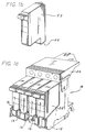
- FIG. 10 is an illustrative diagram of a disassembled improved electrical interconnect system for a unitary interconnect in accordance with the present invention.
- FIG. 11 is an illustrative diagram showing contacts on a circuit board corresponding to contacts on a unitary interconnect constructed in accordance with the present invention.
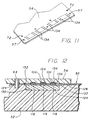
- FIG. 12 is an illustrative diagram of an elevation section along line 12-12 of FIG. 10 of an assembled improved electrical interconnect system for a unitary interconnect constructed in accordance with the present invention.
- Fig. 1 is a perspective view of a thermal inkjet desktop printer incorporating the teachings of the present invention.
- the printer 10 includes a housing 11a and a protective front access lid 11b .
- a carriage assembly 18 which has four inkjet pens 22 , is adapted for reciprocal motion along carriage bar 15 .
- the position of the carriage assembly 18 in the carriage scan axis along carriage bar 15 is determined by a carriage positioning mechanism (not shown) on the carriage assembly 18 that senses its position relative to carriage encoder strip 17 .
- An input tray 19a holds an media input stack 13 and after printing the printed media is held by an output tray 19b .
- a color inkjet printer/plotter has four inkjet pens 22 , one that stores black ink, and three that store colored inks, e.g., magenta, cyan and yellow. The colors from the three color pens are mixed to obtain any particular color.
- FIG. 1b is a detailed illustration of an inkjet pen 22 that includes heater circuits, which when activated cause ink to be ejected from the inkjet pen 22 at end 26 .
- FIG. 1c illustrates carriage assembly 18 including four inkjet pens 22 installed in four pen stalls 16 in unitary housing 12 with cover 24 placed on top.
- the inkjet pens 22 are held in unitary housing 12 by unitary spring clamp assembly 28 , which is installed onto unitary housing 12 , as shown in FIG. 2a.
- the tops of the inkjet pens 22 are retained by cam clamps 32 on unitary spring clamp assembly 28 when the inkjet pens 22 are inserted into unitary housing 12 .
- FIG. 2b shows the position of cam clamps 32 on spring 30 to form unitary spring clamp assembly 28 .
- unitary clamp assembly 28 is installed onto unitary housing 12 , as shown in FIG. 2a, then removable frame circuit assembly 14 is placed into unitary housing 12 , as shown in FIGs. 3a and 3b. Removable frame circuit assembly 14 is fastened to unitary housing 12 with a single attachment device 20 , as shown in FIG 3c.
- FIG. 4 is an illustrative diagram showing a detailed view of the unitary housing 12 in accordance with the present invention.
- the unitary housing 12 is a one piece construction and retains the inkjet pens in a fixed relation to each other and the inkjet printer.
- a first portion 47 integral to the unitary housing extends along a first axis and is adapted to engage the carriage bar 15 .
- the pen stalls 16 each extend along a second axis and are substantially transverse to and integral with the first portion 47 .
- Rear compartment 38 extending along a third axis, is substantially transverse to and integral with the first and second portions and adapted to retain a substantially planar frame circuit assembly 14 within a plane defined by the first and third axes.
- the unitary housing provides a substantially smaller carriage assembly than the prior art.
- the unitary housing 12 has a front wall 41 , two lateral walls 42 , three pen stall walls 44 , and rear wall 43 , which form four pen stalls 16 . It also has a rear compartment 38 formed by lateral walls 42 , rear wall 43 , base 45 , and the spaces between pen stall walls 44 closest to base 45 .
- the four pen stalls 16 have passages that communicate to the rear stall between rear wall 43 and base 45 and between the pen stall walls 44 .
- the removable frame circuit assembly 14 is installed into the rear compartment 38 in unitary housing 12 , as shown in FIGs. 3a - 3c.
- the single attachment device 20 which can be a simple screw, mates with single attachment point 40 on unitary housing 12 to attach removable frame circuit assembly 14 to unitary housing 12 .
- the removable frame circuit assembly 14 needs to be properly aligned to the unitary housing 12 , because there are electrical contacts on the inkjet pens that when mounted in pen stalls 16 must make proper electrical contact with electrical contacts on the removable frame circuit assembly 14 .
- the alignment of removable frame circuit assembly 14 to unitary housing 12 is provided by two vertical alignment pins 46 for vertical alignment and by single horizontal alignment wall 48 for horizontal alignment.
- the vertical alignment pins 46 mate with alignment holes 68 on removable frame circuit assembly 14 , shown in FIG. 5b.
- the single horizontal alignment wall 48 is a vertical wall in unitary housing 12 .
- Alignment slot 70 on removable frame circuit assembly 14 shown in FIG. 5b, slides over and aligns to single horizontal alignment wall 48 when the removable frame circuit assembly 14 is assembled with unitary housing 12 .
- FIGs. 5a and 5b are illustrative diagrams showing the assembly of a unitary frame 52 with circuit board 54 and unitary interconnect 56 to form removable frame circuit assembly 14 in accordance with the present invention.
- the unitary interconnect 56 is aligned to unitary frame 52 by alignment pins 64 and unitary interconnect alignment pins 66 on unitary frame 52 that fit into alignment holes 108 and alignment holes 110 , respectively, on unitary interconnect 56 as shown in FIG. 7.
- the unitary interconnect 56 is wrapped over extensions 78 that are on one end of unitary frame 52 .
- the unitary interconnect 56 provides a shorter interconnect between the inkjet pens 22 and the circuit board 54 than the separate flexible circuits for each inkjet pen of the prior art, which is partially a result of the substantially smaller carriage assembly provided by unitary housing 12 .
- the unitary interconnect 56 has two areas of electrical contacts: electrical contacts 60 on unitary interconnect first end 74 and electrical contacts 62 on unitary interconnect second end 75 .
- the electrical contacts 62 interconnect with circuit board 54 .
- the electrical contacts 60 are for electrical interconnection with the inkjet pens 22 held in pen stalls 16 .
- the circuit board 54 is attached to the unitary frame 52 with devices such as screws 58 that pass through circuit board attachment holes 57 and unitary interconnect holes 59 and into unitary frame 52 .
- the single attachment device 20 passes through circuit board attachment hole 61 and unitary frame hole 63 , when attaching removable frame circuit assembly 14 to unitary housing 12 .
- FIGs. 6a and 6b are illustrative diagrams showing the assembly of unitary interconnect 56 on unitary frame 52 and circuit board 54 to form a removable frame circuit assembly 14 in accordance with the present invention.
- the unitary interconnect 56 is first aligned and attached to unitary frame 52 .
- an elastomeric pad 124 is placed into recess 130 in unitary frame 52 and then the unitary interconnect 56 is wrapped over one end of unitary frame 52 and the electrical contacts 62 are aligned onto unitary frame 52 and over the elastomeric pad 124 .
- the circuit board 54 is attached to the unitary frame 52 to make electrical contact with electrical contacts 62 on unitary interconnect 56 .
- the electrical interconnection of the unitary interconnect 56 with the circuit board 54 is described in further detail with reference to FIG. 10 later in this specification.
- FIG. 7 is an illustrative detailed diagram of the unitary interconnect 56 constructed in accordance with the present invention.
- the unitary interconnect 56 includes substrate 88 , which for convenience of description has a unitary interconnect first end 74 and a unitary interconnect second end 75 . As discussed above, there are alignment holes 108 and alignment holes 110 on substrate 88 for alignment to the unitary frame 52 .
- each identical individual set of electrical signal and ground contacts 90 in FIG. 7 has twenty three electrical signal contacts 94 and nine electrical ground contacts 96 .
- the electrical contacts 60 of FIG. 5b are simplified representations of the electrical signal contacts 94 and electrical ground contacts 96 , as shown more accurately in FIG. 7.
- the electrical contacts 62 of FIG. 5a are simplified representations of the electrical signal contacts 100 and electrical ground contacts 102 , as shown more accurately in FIG. 7.
- the number of heater circuits that are activated at any one time are determined by the pattern being printed.
- the advantage of the design for unitary interconnect 56 is that a common conductive ground layer 122 is used to interconnect the nine electrical ground contacts 96 for each of the four identical individual sets of electrical signal and ground contacts 90 to all sixteen electrical ground contacts 102 .
- a total of thirty six electrical ground contacts 96 are interconnected via common conductive ground layer 122 with sixteen electrical ground contacts 102 .
- each inkjet pen can use all sixteen electrical ground contacts 102 for a ground return. Sharing the ground contacts reduces ground fluctuations for the inkjet pens and improves their performance.
- each inkjet pen has a reduced number of electrical ground contacts, which can cause ground fluctuations if a large number of heater circuits are activated in one inkjet pen.
- FIG. 8 is an illustrative diagram of section 8-8 of FIG. 7 showing protrusions 116 on substrate 88 constructed in accordance with the present invention. As shown in FIG. 8, there are electrical signal contacts 94 or electrical ground contacts 96 on protrusions 116 .
- FIG. 9 is an illustrative diagram of section 9-9 of FIG. 7 showing protrusions 118 on substrate 88 . As shown in FIG. 9, there are electrical signal contacts 100 or electrical ground contacts 102 on protrusions 118 . The electrical contacts on protrusions 116 make contact with electrical contacts on the inkjet pens 22 and the electrical contacts on protrusions 118 make contact with electrical contacts on circuit board 54 .
- FIG. 10 an improved electrical interconnect system 140 for a flexible circuit with a circuit board is shown.
- the unitary interconnect 56 shown in detail in FIG. 7, is constructed with a polyester or polyimide material such as Mylar or Kapton substrate 88 onto which multiple conductors are deposited.
- the conductors are made of copper and can be covered with another layer of Mylar or Kapton.
- Electrical contacts 62 are located on protrusions 118 on substrate 88 , as shown in FIG. 9.
- FIG. 11 shows the opposite side of circuit board 54 with circuit board contacts 134 , which according to the present invention are interconnected with electrical contacts 62 on unitary interconnect 56 .
- the arrangement of circuit board contacts 134 on circuit board 54 correspond to the arrangement of electrical contacts 62 on unitary interconnect 56 , which is shown in detail in FIG. 7.
- Each of the circuit board contacts 134 are gold plated and the electrical contacts 62 are also gold plated to insure a low resistance electrical path.
- the circuit board 54 and unitary interconnect 56 are assembled on a unitary frame 52 , which can be constructed of plastic, because only low pressure is used to interconnect circuit board contacts 134 and electrical contacts 62 .
- An elastomeric pad 124 which can be constructed of urethane rubber, provides a spring function and is mounted into recess 130 in unitary frame 52 .
- the improved electrical interconnect system 140 is assembled by using screws 58 that are inserted through circuit board attachment hole 57 on circuit board 54 and unitary interconnect holes 59 on unitary interconnect 56 and then screwed into attachment holes 126 on unitary frame 52 .
- the electrical contacts 62 on unitary interconnect 56 are aligned to circuit board contacts 134 on circuit board 54 by alignment pins 64 coupled to unitary frame 52 , which are inserted through alignment holes 108 on unitary interconnect 56 and alignment holes 72 on circuit board 54 .
- alignment pins 64 coupled to unitary frame 52 , which are inserted through alignment holes 108 on unitary interconnect 56 and alignment holes 72 on circuit board 54 .
- FIG. 12 is an illustrative diagram of an elevation section along line 12-12 of FIG. 10 of an assembled improved electrical interconnect system for a flexible circuit constructed in accordance with the present invention.
- the elastomeric pad 124 is shown to fit within recess 130 in unitary frame 52 .
- the elastomeric pad 124 provides a spring function that bears upon the electrical contacts 100 on protrusions 118 between the elastomeric pad 124 and the circuit board 54 .
- the unitary frame 52 has bevels 132 between the recess 130 and the top surface 128 of the unitary frame 52 .
- each bevel 132 provides relief for allowing the unitary interconnect 56 to deform during assembly so that all of the electrical contacts 100 on protrusions 118 make contact with all of the circuit board contacts 134 on circuit board 54 .
- Bevels 132 provide relief to the portion of unitary interconnect 56 between elastomeric pad 124 and circuit board 54 .
- circuit contact recesses 136 which contain circuit board contacts 134 .
- the circuit contact recesses 136 on circuit board 54 are the result of a coating such as a solder mask that is applied over the conductors on circuit board 54 to protect the conductors from corrosion and to prevent solder bridging. This leaves slight circuit contact recesses 136 on the order of .001 - .002 inches deep at each of the circuit board contacts 134 , which as discussed above are gold plated.
- the portion of unitary interconnect 56 between elastomeric pad 124 and circuit board 54 deforms, which allows the protrusions 118 on unitary interconnect 56 to align with the circuit contact recesses 136 on circuit board 54 to ensure proper electrical contact.
- the improved electrical interconnect system for a flexible circuit 140 is easy to assemble and disassemble by simply loosening or tightening screws 58 .
- the interconnect density exceeds 150 contacts per square inch, which provides a high density interconnect system.
- the improved unitary interconnect system provides an interconnect system that reduces cost, is easier to assemble and align, and provides ground plane sharing for all of the inkjet pens.
- the improved carriage assembly has reduced cost and is easier to assemble, align and service without the need for any special tools.
Landscapes
- Ink Jet (AREA)
- Accessory Devices And Overall Control Thereof (AREA)
- Common Mechanisms (AREA)
Applications Claiming Priority (3)
| Application Number | Priority Date | Filing Date | Title |
|---|---|---|---|
| US5561893A | 1993-04-30 | 1993-04-30 | |
| US55618 | 1993-04-30 | ||
| EP93120341A EP0622240B1 (fr) | 1993-04-30 | 1993-12-16 | Chariot modulaire pour imprimante par jet d'encre |
Related Parent Applications (2)
| Application Number | Title | Priority Date | Filing Date |
|---|---|---|---|
| EP93120341A Division EP0622240B1 (fr) | 1993-04-30 | 1993-12-16 | Chariot modulaire pour imprimante par jet d'encre |
| EP93120341.8 Division | 1993-12-16 |
Publications (3)
| Publication Number | Publication Date |
|---|---|
| EP0807529A2 true EP0807529A2 (fr) | 1997-11-19 |
| EP0807529A3 EP0807529A3 (fr) | 1998-02-11 |
| EP0807529B1 EP0807529B1 (fr) | 2000-07-12 |
Family
ID=21999057
Family Applications (2)
| Application Number | Title | Priority Date | Filing Date |
|---|---|---|---|
| EP93120341A Expired - Lifetime EP0622240B1 (fr) | 1993-04-30 | 1993-12-16 | Chariot modulaire pour imprimante par jet d'encre |
| EP97113771A Expired - Lifetime EP0807529B1 (fr) | 1993-04-30 | 1993-12-16 | Assemblage à chariot pour retenir deux cartouches d'impression à jet d'encre |
Family Applications Before (1)
| Application Number | Title | Priority Date | Filing Date |
|---|---|---|---|
| EP93120341A Expired - Lifetime EP0622240B1 (fr) | 1993-04-30 | 1993-12-16 | Chariot modulaire pour imprimante par jet d'encre |
Country Status (4)
| Country | Link |
|---|---|
| US (1) | US5539436A (fr) |
| EP (2) | EP0622240B1 (fr) |
| JP (1) | JP3420637B2 (fr) |
| DE (2) | DE69319092T2 (fr) |
Families Citing this family (25)
| Publication number | Priority date | Publication date | Assignee | Title |
|---|---|---|---|---|
| US6084617A (en) * | 1995-10-31 | 2000-07-04 | Hewlett-Packard Company | Narrow body inkjet print cartridge having parallel configuration of internal components |
| KR100195908B1 (ko) * | 1996-10-28 | 1999-06-15 | 윤종용 | 잉크젯 프린터의 헤드 구조 |
| EP0890442A1 (fr) * | 1997-06-18 | 1999-01-13 | Hewlett-Packard Company | Imprimante à jet d'encre avec système d'alignement et méthode |
| FR2773248B1 (fr) * | 1997-12-30 | 2000-03-17 | Neopost Ind | Module d'impression postale numerique securise |
| US6082854A (en) * | 1998-03-16 | 2000-07-04 | Hewlett-Packard Company | Modular ink-jet hard copy apparatus and methodology |
| EP0953456A1 (fr) * | 1998-04-29 | 1999-11-03 | Hewlett-Packard Company | Architecture integrée d'une cartouche d'encre animé d'un mouvement de va-et-vient à paliers intégrés |
| US6224192B1 (en) * | 1998-10-06 | 2001-05-01 | Hewlett-Packard Company | Inkjet printing systems using a modular print cartridge assembly |
| US6065826A (en) * | 1998-10-06 | 2000-05-23 | Hewlett-Packard Company | Modular print cartridge receptacle for use in inkjet printing systems |
| US6280017B1 (en) * | 1998-10-27 | 2001-08-28 | Canon Kabushiki Kaisha | Recording apparatus |
| USD430897S (en) * | 1999-06-11 | 2000-09-12 | Lexmark International, Inc. | Ink cartridge for printer |
| US6120201A (en) * | 1999-07-12 | 2000-09-19 | Hewlett-Packard Company | Printer with front portion providing access to print mechanism |
| US6386681B1 (en) | 2000-02-01 | 2002-05-14 | Lexmark International, Inc. | Carrier assembly and ink jet printhead assembly associated therewith |
| US6199977B1 (en) | 2000-04-13 | 2001-03-13 | Lexmark International, Inc. | Cartridge body for ink jet printer |
| US6729714B2 (en) * | 2001-07-31 | 2004-05-04 | Hewlett-Packard Development Company, L.P. | Separable key for establishing detachable printer component compatibility with a printer |
| JP2003182113A (ja) * | 2001-10-12 | 2003-07-03 | Ricoh Co Ltd | カラーインクジェット記録装置及び複写装置 |
| US20030202062A1 (en) * | 2002-04-25 | 2003-10-30 | Steinmetz Charles R. | Configurable ink supply system |
| US6715857B2 (en) | 2002-09-05 | 2004-04-06 | Lexmark International, Inc. | Printhead carrier housing and flexible printed circuit attached to same |
| JP3807359B2 (ja) * | 2002-10-30 | 2006-08-09 | セイコーエプソン株式会社 | 液体噴射装置 |
| JP4563019B2 (ja) * | 2002-11-07 | 2010-10-13 | オセ−テクノロジーズ ビーブイ | プリントキャリッジアセンブリ及びそのアセンブリにプリンタヘッドホルダーを設置するための方法 |
| EP1418054B1 (fr) * | 2002-11-07 | 2006-08-09 | Océ-Technologies B.V. | Ensemble d'un chariot d'impression et méthode pour le montage d'un support de tête d'impression sur l'ensemble |
| JP4161213B2 (ja) * | 2004-01-23 | 2008-10-08 | ブラザー工業株式会社 | インクジェット記録ヘッドにおける配線基板の接合構造及びその接合方法 |
| KR100584611B1 (ko) * | 2004-11-27 | 2006-06-01 | 삼성전자주식회사 | 잉크젯 프린터 |
| JP4726156B2 (ja) * | 2005-02-24 | 2011-07-20 | 株式会社リコー | 画像形成装置 |
| WO2010087857A1 (fr) * | 2009-01-30 | 2010-08-05 | Hewlett-Packard Development Company, L.P. | Circuit flexible |
| KR101278331B1 (ko) * | 2010-10-07 | 2013-06-25 | 삼성전기주식회사 | 솔더 볼 흡착용 지그 |
Citations (5)
| Publication number | Priority date | Publication date | Assignee | Title |
|---|---|---|---|---|
| US4775868A (en) * | 1982-04-19 | 1988-10-04 | Canon Kabushiki Kaisha | Recording apparatus |
| EP0313205A2 (fr) * | 1987-10-23 | 1989-04-26 | Hewlett-Packard Company | Dispositif pour l'alignement de la tête d'impression et du chariot et mécanisme de verrouillage de l'interconnexion électronique |
| EP0315417A2 (fr) * | 1987-11-03 | 1989-05-10 | Hewlett-Packard Company | Imprimante munie de têtes d'impression ou de plumes d'enregistrement interchangeables et identifiables |
| EP0581297A2 (fr) * | 1992-07-30 | 1994-02-02 | Canon Kabushiki Kaisha | Tête d'enregistrement et appareil d'enregistrement l'utilisant |
| US5359357A (en) * | 1992-03-19 | 1994-10-25 | Fuji Xerox Co., Ltd. | Ink-jet recording apparatus |
Family Cites Families (7)
| Publication number | Priority date | Publication date | Assignee | Title |
|---|---|---|---|---|
| US4074284A (en) * | 1976-06-07 | 1978-02-14 | Silonics, Inc. | Ink supply system and print head |
| US4827294A (en) * | 1985-11-22 | 1989-05-02 | Hewlett-Packard Company | Thermal ink jet printhead assembly employing beam lead interconnect circuit |
| US4806106A (en) * | 1987-04-09 | 1989-02-21 | Hewlett-Packard Company | Interconnect lead frame for thermal ink jet printhead and methods of manufacture |
| US4755836A (en) * | 1987-05-05 | 1988-07-05 | Hewlett-Packard Company | Printhead cartridge and carriage assembly |
| US4878070A (en) * | 1988-10-17 | 1989-10-31 | Xerox Corporation | Thermal ink jet print cartridge assembly |
| JPH02198881A (ja) * | 1989-01-27 | 1990-08-07 | Shimadzu Corp | プリンタ |
| US4940998A (en) * | 1989-04-04 | 1990-07-10 | Hewlett-Packard Company | Carriage for ink jet printer |
-
1993
- 1993-12-16 DE DE69319092T patent/DE69319092T2/de not_active Expired - Lifetime
- 1993-12-16 EP EP93120341A patent/EP0622240B1/fr not_active Expired - Lifetime
- 1993-12-16 DE DE69329041T patent/DE69329041T2/de not_active Expired - Lifetime
- 1993-12-16 EP EP97113771A patent/EP0807529B1/fr not_active Expired - Lifetime
-
1994
- 1994-04-13 JP JP09928494A patent/JP3420637B2/ja not_active Expired - Fee Related
-
1995
- 1995-04-28 US US08/431,395 patent/US5539436A/en not_active Expired - Lifetime
Patent Citations (5)
| Publication number | Priority date | Publication date | Assignee | Title |
|---|---|---|---|---|
| US4775868A (en) * | 1982-04-19 | 1988-10-04 | Canon Kabushiki Kaisha | Recording apparatus |
| EP0313205A2 (fr) * | 1987-10-23 | 1989-04-26 | Hewlett-Packard Company | Dispositif pour l'alignement de la tête d'impression et du chariot et mécanisme de verrouillage de l'interconnexion électronique |
| EP0315417A2 (fr) * | 1987-11-03 | 1989-05-10 | Hewlett-Packard Company | Imprimante munie de têtes d'impression ou de plumes d'enregistrement interchangeables et identifiables |
| US5359357A (en) * | 1992-03-19 | 1994-10-25 | Fuji Xerox Co., Ltd. | Ink-jet recording apparatus |
| EP0581297A2 (fr) * | 1992-07-30 | 1994-02-02 | Canon Kabushiki Kaisha | Tête d'enregistrement et appareil d'enregistrement l'utilisant |
Non-Patent Citations (1)
| Title |
|---|
| 26837: "Flex Circuit Wrap Connector" RESEARCH DISCLOSURE, no. 268, August 1986, EMSWORTH HAMPSHIRE, GREAT-BRITTAIN, page 469 XP002049177 * |
Also Published As
| Publication number | Publication date |
|---|---|
| US5539436A (en) | 1996-07-23 |
| DE69319092T2 (de) | 1999-01-07 |
| JP3420637B2 (ja) | 2003-06-30 |
| JPH07125380A (ja) | 1995-05-16 |
| EP0622240B1 (fr) | 1998-06-10 |
| EP0807529B1 (fr) | 2000-07-12 |
| DE69329041D1 (de) | 2000-08-17 |
| EP0622240A3 (fr) | 1996-04-03 |
| EP0622240A2 (fr) | 1994-11-02 |
| DE69329041T2 (de) | 2001-03-22 |
| DE69319092D1 (de) | 1998-07-16 |
| EP0807529A3 (fr) | 1998-02-11 |
Similar Documents
| Publication | Publication Date | Title |
|---|---|---|
| EP0807529B1 (fr) | Assemblage à chariot pour retenir deux cartouches d'impression à jet d'encre | |
| US5533904A (en) | Electrical interconnect system for multiple flexible circuits | |
| EP0622193B1 (fr) | Un système d'interconnexion unitaire perfectionné pour une imprimante à jet d'encre | |
| US5684518A (en) | Interconnect scheme for mounting differently configured printheads on the same carriage | |
| US5712669A (en) | Common ink-jet cartridge platform for different printheads | |
| US5949453A (en) | Mixed resolution printing for color and monochrome printers | |
| US6174046B1 (en) | Reliable contact pad arrangement on plastic print cartridge | |
| JPH05270099A (ja) | 熱インクジェットノズル配列 | |
| US5883646A (en) | Compact flex-circuit for modular assembly of optical sensor components in an inkjet printer | |
| US6003974A (en) | Unitary interconnect system for an inkjet printer | |
| EP0820871B1 (fr) | Tête d'enregistrement du type à jet d'encre | |
| EP0730975B1 (fr) | Elément d'interconnexion souple pour monter des cartouches d'impression amovibles sur un chariot | |
| US8210651B2 (en) | Modular printhead incorporating alignment mechanism for printhead module | |
| US5975679A (en) | Dot alignment in mixed resolution printer | |
| EP0268395A2 (fr) | Tête d'impression pour imprimante à jet d'encre | |
| KR100385987B1 (ko) | 잉크젯 프린터의 전기적 접점장치 | |
| EP0730969B1 (fr) | Alignement de points pour imprimante à résolution mixte | |
| JPH08108546A (ja) | インクジェット記録装置 | |
| JPH07195684A (ja) | 高精度スタック可能インクジェットプリントバー及びその製造方法 |
Legal Events
| Date | Code | Title | Description |
|---|---|---|---|
| PUAI | Public reference made under article 153(3) epc to a published international application that has entered the european phase |
Free format text: ORIGINAL CODE: 0009012 |
|
| 17P | Request for examination filed |
Effective date: 19970808 |
|
| AC | Divisional application: reference to earlier application |
Ref document number: 622240 Country of ref document: EP |
|
| AK | Designated contracting states |
Kind code of ref document: A2 Designated state(s): DE FR GB IT |
|
| PUAL | Search report despatched |
Free format text: ORIGINAL CODE: 0009013 |
|
| AK | Designated contracting states |
Kind code of ref document: A3 Designated state(s): DE FR GB IT |
|
| 17Q | First examination report despatched |
Effective date: 19990409 |
|
| GRAG | Despatch of communication of intention to grant |
Free format text: ORIGINAL CODE: EPIDOS AGRA |
|
| GRAG | Despatch of communication of intention to grant |
Free format text: ORIGINAL CODE: EPIDOS AGRA |
|
| GRAH | Despatch of communication of intention to grant a patent |
Free format text: ORIGINAL CODE: EPIDOS IGRA |
|
| GRAH | Despatch of communication of intention to grant a patent |
Free format text: ORIGINAL CODE: EPIDOS IGRA |
|
| ITF | It: translation for a ep patent filed | ||
| GRAA | (expected) grant |
Free format text: ORIGINAL CODE: 0009210 |
|
| AC | Divisional application: reference to earlier application |
Ref document number: 622240 Country of ref document: EP |
|
| AK | Designated contracting states |
Kind code of ref document: B1 Designated state(s): DE FR GB IT |
|
| REF | Corresponds to: |
Ref document number: 69329041 Country of ref document: DE Date of ref document: 20000817 |
|
| ET | Fr: translation filed | ||
| RAP2 | Party data changed (patent owner data changed or rights of a patent transferred) |
Owner name: HEWLETT-PACKARD COMPANY, A DELAWARE CORPORATION |
|
| PLBE | No opposition filed within time limit |
Free format text: ORIGINAL CODE: 0009261 |
|
| STAA | Information on the status of an ep patent application or granted ep patent |
Free format text: STATUS: NO OPPOSITION FILED WITHIN TIME LIMIT |
|
| 26N | No opposition filed | ||
| REG | Reference to a national code |
Ref country code: GB Ref legal event code: IF02 |
|
| REG | Reference to a national code |
Ref country code: GB Ref legal event code: 732E |
|
| REG | Reference to a national code |
Ref country code: FR Ref legal event code: TP |
|
| PGFP | Annual fee paid to national office [announced via postgrant information from national office to epo] |
Ref country code: IT Payment date: 20061231 Year of fee payment: 14 |
|
| PGFP | Annual fee paid to national office [announced via postgrant information from national office to epo] |
Ref country code: GB Payment date: 20071227 Year of fee payment: 15 Ref country code: FR Payment date: 20070207 Year of fee payment: 14 |
|
| REG | Reference to a national code |
Ref country code: FR Ref legal event code: ST Effective date: 20081020 |
|
| PG25 | Lapsed in a contracting state [announced via postgrant information from national office to epo] |
Ref country code: FR Free format text: LAPSE BECAUSE OF NON-PAYMENT OF DUE FEES Effective date: 20071231 |
|
| GBPC | Gb: european patent ceased through non-payment of renewal fee |
Effective date: 20081216 |
|
| PG25 | Lapsed in a contracting state [announced via postgrant information from national office to epo] |
Ref country code: IT Free format text: LAPSE BECAUSE OF NON-PAYMENT OF DUE FEES Effective date: 20071216 |
|
| PG25 | Lapsed in a contracting state [announced via postgrant information from national office to epo] |
Ref country code: GB Free format text: LAPSE BECAUSE OF NON-PAYMENT OF DUE FEES Effective date: 20081216 |
|
| PGFP | Annual fee paid to national office [announced via postgrant information from national office to epo] |
Ref country code: DE Payment date: 20121231 Year of fee payment: 20 |
|
| REG | Reference to a national code |
Ref country code: DE Ref legal event code: R071 Ref document number: 69329041 Country of ref document: DE |
|
| PG25 | Lapsed in a contracting state [announced via postgrant information from national office to epo] |
Ref country code: DE Free format text: LAPSE BECAUSE OF EXPIRATION OF PROTECTION Effective date: 20131217 |