EP0807373B1 - Regelung für einen halbgetragenen Pflug - Google Patents
Regelung für einen halbgetragenen Pflug Download PDFInfo
- Publication number
- EP0807373B1 EP0807373B1 EP97303101A EP97303101A EP0807373B1 EP 0807373 B1 EP0807373 B1 EP 0807373B1 EP 97303101 A EP97303101 A EP 97303101A EP 97303101 A EP97303101 A EP 97303101A EP 0807373 B1 EP0807373 B1 EP 0807373B1
- Authority
- EP
- European Patent Office
- Prior art keywords
- plough
- linkage
- tractor
- lowering
- value
- Prior art date
- Legal status (The legal status is an assumption and is not a legal conclusion. Google has not performed a legal analysis and makes no representation as to the accuracy of the status listed.)
- Expired - Lifetime
Links
Images


Classifications
-
- A—HUMAN NECESSITIES
- A01—AGRICULTURE; FORESTRY; ANIMAL HUSBANDRY; HUNTING; TRAPPING; FISHING
- A01B—SOIL WORKING IN AGRICULTURE OR FORESTRY; PARTS, DETAILS, OR ACCESSORIES OF AGRICULTURAL MACHINES OR IMPLEMENTS, IN GENERAL
- A01B63/00—Lifting or adjusting devices or arrangements for agricultural machines or implements
- A01B63/02—Lifting or adjusting devices or arrangements for agricultural machines or implements for implements mounted on tractors
- A01B63/10—Lifting or adjusting devices or arrangements for agricultural machines or implements for implements mounted on tractors operated by hydraulic or pneumatic means
- A01B63/111—Lifting or adjusting devices or arrangements for agricultural machines or implements for implements mounted on tractors operated by hydraulic or pneumatic means regulating working depth of implements
- A01B63/1117—Lifting or adjusting devices or arrangements for agricultural machines or implements for implements mounted on tractors operated by hydraulic or pneumatic means regulating working depth of implements using a hitch position sensor
Definitions
- the present invention relates to a semi-mounted plough control system for an agricultural tractor.
- a semi-mounted plough has a support wheel at the centre or at the far end on which the plough is supported via a hydraulic cylinder, for height adjustment. This means that the height of the near end of the plough, which is mounted on a tractor 3-point linkage and the height of the far end of the plough are controlled by separate hydraulic lines.
- a value is inputted to the control system before ploughing commences which is representative of the length of the plough.
- the control system uses this value together with the sensed speed of the tractor to determine a time delay between the lowering of the front and rear of the plough into work and a similar time delay between removal of the front and rear of the plough from work.
- a system for the control of a semi-mounted plough attached to a tractor linkage, the plough having a support wheel with lifting/lowering means associated therewith, comprises:
- the angle between the ploughing direction and the field boundary is taken into account when setting the delay between the front and rear of the semi-mounted plough being taken out of or put into work, thereby causing the individual ploughshares to enter and leave work in line with the field worked area boundary.
- a tractor 1 has connected up to it a semi-mounted plough 2.
- the plough 2 is mounted on one end on the tractor three-point linkage 3 and at the other is supported by means of a support wheel 4.
- the wheel 4 can be provided towards the centre.
- the plough may be lifted and lowered on the support wheel 4 by means of a hydraulic cylinder 5.
- the three-point linkage can be raised and lowered in a conventional manner by means of hydraulic cylinders 15 whose operation is in turn controlled by an electronic linkage control panel 10 in the tractor cab via an electro-hydraulic valve 9 (or valves).
- the electro-hydraulic valve 9 is connected electronically to the control panel 10 as shown and is also connected to a source 16 of hydraulic pressure and a hydraulic reservoir 17, as well as to the hydraulic cylinders 15 via lines 7.
- the electronic linkage control unit performs the usual linkage control functions known in themselves, including the automatic control of the linkage height based on sensed draft force ("draft control"). It also includes the usual simple linkage raise/lower switch 10a to put an implement mounted on the linkage into work.
- the electronic linkage control unit is connected via a CAN network connection 14 to a tractor function display/monitoring unit 13.
- the hydraulic cylinder 5 on the rear of the plough is fed from a hydraulic line 6 and the supply of fluid along this line is controlled by an electro-hydraulic valve 8.
- the valve 8 is connected in a known manner to a source of hydraulic pressure 16 and the hydraulic reservoir 17, and is electronically connected into the electronic linkage control unit, although it could also be connected into the display/monitoring unit 13. It is also operable by a manual lever 18 associated directly with the valve 8.
- a linkage position sensor 12 provides an electronic output representative of the linkage position and a tractor speed sensor 11 similarly provides an electronic output representative of tractor ground speed. Both sensors are connected to the electronic linkage control unit 10, although they could equally be connected to the monitoring/display unit 13.
- the semi-mounted plough control system as a whole, incorporating the speed and implement linkage position sensors 11, 12, valves 8, 9, control unit 10 and monitoring/display unit 13, etc functions in four distinct operational modes, described in the following paragraphs.
- the first of these modes is “work mode", when the plough is fully engaged in soil.
- the system will control movements of the hydraulic cylinder 5 on the rear of the plough to mirror the movements of the three-point linkage 3, so that the plough is maintained in a horizontal orientation.
- the 3-point linkage will function in "position control” or “draft control” mode, or a mixture of the two as is conventional.
- the second mode of operation is "headland mode". In this mode, the tractor linkage and the wheel support are at a predefined maximum height for transport purposes.
- the third mode is "furrow entry mode", which is entered when the linkage raise/lower switch 10a on the electronic control unit 10 is toggled to cause the plough to be lowered into work.
- the front end of the plough, mounted on the tractor linkage is lowered into work in exactly the same way that a fully mounted plough would be.
- the rear end of the plough is lowered in two stages: firstly it is lowered to a predefined height just above the ground and then, after a given period of time, it is lowered into work. At that point, the system transfers into work mode.
- the fourth mode is "furrow exit mode". This mode is entered when the linkage raise/lower switch 10a is toggled to the "raise” position whilst the plough is in work.
- the switch When the switch is toggled, the tractor linkage, and therefore the front of the plough, are raised out of work to the fully raised position as is conventional.
- the rear of the plough As the front of the plough is raised, the rear of the plough is raised slightly with respect to the support wheel. This is to compensate for plough rotation effects, as explained later on.
- the actual level of the rear of the plough in the ground will stay the same, or raise slightly so that it is still in the ground but at a shallower depth. After a period of time, the rear of the plough is fully raised out of work.
- the control system then enters headland mode.
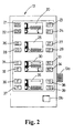
- FIG. 2 is a schematic illustration of the display/monitoring device 13, showing the plough control set-up screen on its multi-function display.
- an icon 20 showing a semi-mounted plough in a horizontal raised position.
- the figure in the upper lefthand window 21 is a stored value for the maximum desired height of the tractor linkage.
- the tractor linkage needs to be raised to an appropriate maximum upper position.
- the numerical value shown in the lower window 22 will change.
- a "save" button 13a is depressed and this value is then stored by the system and transferred to the upper window 21 which indicates the maximum linkage height value currently stored by the system.
- the upper and lower windows 23, 24 on the right-hand side of the raised plough icon are used in the same way to set the maximum height for the plough on the support wheel 4.
- the manual control 18 for the electro-hydraulic valve 8 controlling the hydraulic cylinder 5 on the rear of the plough is adjusted so that the cylinder 5 is fully extended and the rear of the plough is at its maximum height. As this is being done, the value in the lower window, 24 is changing.
- the "save" button 13a is depressed and this value is transferred to the upper window 23 and stored in the control system.
- the second icon 25, showing a plough in its lowered position, is used for storing the lowest possible position for the front and rear of the plough in the same way as for the maximum height position. Assuming a reversible plough is fitted, the plough is first rotated into a position where each set of ploughshares projects horizontally, and the tractor linkage control and the manual control on the electro-hydraulic valve 8 are both adjusted so that the front and rear of the plough are in their lowest possible position. The variable values shown in the lower windows 27, 28 on each side of the icon 25 are then saved into the control system, at which time they are also displayed in the respective upper windows 26, 27.
- the third icon down on the display is used for setting a notional plough length value for use by the system when in furrow entry mode.
- this value will not actually be in meters or feet, but will simply be a number suitable for the particular plough being used.
- This value is set using windows 31, 32 on the left-hand side of the icon 30.
- the upper window 31 shows the current saved value for plough "entry" length, whilst the value displayed in the lower window will change as the control 13a on the display/monitoring unit 13 is adjusted.
- a "save" button 13b is depressed and this value is stored and displayed on the upper window 31.
- This value will generally be related to the length of the plough, although there may be slight differences between ideal values for different ploughs of the same length. To some extent, the optimum value is best determined by trial and error.
- the third icon 30 On the right-hand side of the third icon 30 are upper and lower windows 33, 34 showing values for the "partial lowering" of the rear of the plough.
- the linkage raise/lower switch 10a when toggled to lower the plough into work, the front of the plough is first lowered into work and, at the same time, or shortly afterwards the rear of the plough is partially lowered.
- a value representative of the height to which the rear of the implement is lowered in this "partially lowered" position is selected using a manual control 13a on the unit 13 and stored, as with the entry length setting.
- the fourth icon 35 is for setting another notional value for implement length for use in furrow exit mode (using windows 36, 37 on the left-hand side of icon 35) and also for setting a "partial lift" value using the right-hand windows 38, 39.
- a "partial lift" value is representative of the amount by which the plough is raised with respect to the support wheel in furrow exit mode.
- a working screen is called up on the display/monitoring unit 13, as shown in Figure 3.
- the upper half of the screen of the unit 13 is shown in Figure 3 as simply giving the date. This can be altered to a number of other functions, none of which are relevant to the present invention and will be discussed no further.
- the lower half of the screen is the plough control "working screen”. This comprises a semi-mounted plough icon in the top left of the working screen which simply indicates the function of the screen, and an ON/OFF indicator in the bottom left-hand comer which indicates whether the semi-mounted plough control system is active or not.
- the working screen also comprises three figures 42, 43, 44, whose significance will be explained below.
- the set up values need not be re-set until the plough is removed.
- the tractor electronics are powered up, it is necessary specifically to activate semi-mounted plough control mode by going to the working screen and depressing a button (not shown) on the unit 13 to change the ON/OFF indicator to ON.
- the semi-mounted plough control system assumes that the tractor is positioned on a field headland with the linkage and the wheel support in the maximum height position.
- the figure 42 in the top right-hand comer of the screen is a value from 0 - 99 representative of the support wheel height.
- the figures 43, 44 on the left and right centre portion of the working screen represent adjustments to the plough length value determined by the geometry of the field, in particular the angle between the desired ploughing direction and the field headlands.
- each of these values is set to zero, as will be the case when the working screen is first entered after setting the system up.
- This setting would be appropriate for ploughing a field where the furrows are to be perpendicular to the headlands at each end.
- the operator simply toggles the linkage raise/lower switch on the linkage control unit when it is desired to put the plough into work.
- the system will then enter furrow entry mode and the supply of hydraulic fluid to the support wheel cylinder will be automatically controlled so that the rear of the plough first descends to a partially lowered position and then, after a time delay determined by the plough "entry" length value stored by the system, is lowered into work.
- Figure 4 shows a more normal irregular field with headlands A, B non-perpendicular to the ploughing direction C.
- the figure 43 on the working screen may be adjusted from zero to an appropriate negative value whose magnitude reflects the magnitude of the obtuse angle made by the desired worked area boundary a to the ploughing direction C. If the line a were at an acute angle to direction C then of course a positive value would be input. In practice, the value is input by rotating the control 13a on the side of the unit 13.
- the operator moves the tractor off, toggles the linkage raise/lower switch 10a and the front of the plough then enters work followed by the rear of the plough, after an appropriately adjusted time delay.
- the system then enters work mode.
- the raise/lower switch is toggled and the front of the implement is lifted out of work followed after a suitable time delay by the rear of the plough.
- the tractor then enters headland mode.
- the system automatically causes the sign of the right-hand figure 44 (the B headland figure) to change. This is necessary because, if a reversible plough is used as is almost universal these days, the angle which the plough makes with the direction of travel of the tractor will change when the plough is reversed. Of course, if a non-reversible plough is used, the sign change would not be necessary.
- an option is provided for disabling this sign reversing function.
- the time delay set by the system in conjunction with sensed speed amounts to setting the distance travelled between raising/lowering of the three point linkage and raising/lowering of the rear of the plough.
- a "distance travelled" sensor is employed instead of the speed sensor and the system controls lowering/raising of the rear of the plough after a given sensed distance rather than after a given elapsed time.
- the system recognises the changes between these four phases by detecting the raising and lowering of the tractor linkage, eg from the action of the linkage raise/lower switch on the electronic linkage control unit. If it is desired to set the adjustment values 43, 44 before the ploughing operation commences, this can be easily done simply by raising or lowering the linkage whilst stationary.
- the control system will normally take into account tractor speed when setting the time delay between lifting/lowering of the front and rear of the plough, but a time limit is imposed (eg 7 seconds) after which the rear of the plough will be raised/lowered, irrespective of tractor speed. This allows this stationary setting of the adjustment values 43, 44.
- the maximum time limit also has safety implications.
- a manual control feature is provided to move the system between the four phases, either alternatively or in addition to the automatic "count" of lifting/lowering operations.
- this value is set by lowering the whole plough so that it is horizontal with one set of ploughshares just clearing the ground.
- the idea of this is that the ploughshares will be poised ready to be lowered into work rather than having to drop a great distance. If the rear ploughshares were not poised in this way, an additional time factor would have to be set into the plough entry length figure to allow for the descent of the rear ploughshares from their fully raised position.
- Another advantage of partially lowering the rear ploughshares before entering work is that it avoids an excessively steep entry angle for the front ploughshares which could result in them digging too deep.
- the partial lowering figure also takes into account the rotation effect on a semi-mounted plough when the front of the plough is lowered. This is more pronounced in semi-mounted ploughs with a centre wheel rather than a wheel at the rear, but occurs to a certain extent in both types. As the front of the plough is lowered, the plough support wheel acts as a pivot and the rear end of the plough is in fact raised. Accordingly, the setting of the partial lowering value cannot be exactly determined by simply lowering the plough in a parallel position, and to some extent needs to be determined by trial and error.
- the plough is partially raised at the rear when the front is taken out of work. This is for similar reasons to those explained above, namely to avoid rotation effects.
- the wheel support acts as a pivot and can cause the rear of the plough to be plunged deeply into the soil. This process can also cause the ploughshares to be at an inappropriate angle, which causes the entire plough to "pop" out of the ground too early.
- the partial lift position thus compensates for rotation and can also be used to set a slightly shallower depth for the rear of the plough during the last few metres of its travel whilst the front of the plough is out of work, to avoid an excessively incorrect angle for the ploughshares.
- jagged edges cause wasted work because the area of headland that needs to be ploughed effectively extends from the actual field boundary right up to the furthest part of unworked field from the boundary.
- traction is greatly reduced when driving across a previously ploughed field, and this makes ploughing the "zigzag” areas difficult.
Landscapes
- Life Sciences & Earth Sciences (AREA)
- Engineering & Computer Science (AREA)
- Mechanical Engineering (AREA)
- Soil Sciences (AREA)
- Environmental Sciences (AREA)
- Lifting Devices For Agricultural Implements (AREA)
- Soil Working Implements (AREA)
Claims (5)
- Regelsystem für einen halbgetragenen Pflug (2) an einer Traktoraufhängung (3), wobei der Pflug (2) ein Laufrad (4) mit einer damit verbundenen Einrichtung (5) zum Anheben und Absenken aufweist und das Regelsystemaufweist, dadurch gekennzeichnet, dassa) Elemente zum Eingeben eines Wertes entsprechend einer nominellen Pfluglänge,b) Mittel (11) zum direkten oder indirekten Erfassen des von dem Traktor und dem Pflug zurückgelegten Weges,c) Mittel (10, 13) zum Betätigen der Einrichtung (5) zum Anheben und Absenken während des Zurücklegens eines bestimmten erfassten Weges nach dem Anheben oder Absenken der Aufhängung, wobei dieser bestimmte Weg repräsentativ für den wert der nominellen Pfluglänge ist,vorgesehen sind.d) Mittel (13) zum Abspeichern eines Parameters, der repräsentativ für den Winkel zwischen einer Begrenzungslinie (a, b) des Arbeitsfeldes und einer gewünschten Pflügerichtung (C) ist, unde) Mittel (13) zum Einstellen der Länge des bestimmten erfassten zurückgelegten Weges in Abhängigkeit von dem gespeicherten Parameter für den Winkel
- Regelsystem nach Anspruch 1, dadurch gekennzeichnet, dass die Mittel (11) zum Erfassen des Weges Mittel zum Erfassen der Fahrgeschwindigkeit des Traktors und des Pfluges umfassen.
- Regelsystem nach Anspruch 1 oder 2, dadurch gekennzeichnet, dass die Mittel (13) zum Einstellen für negative und positive Einstellung des bestimmten zurückgelegten Weges entsprechend der Anzahl der Hebe/Senkbetätigungen der Aufhängung (3) ausgebildet sind.
- Regelsystem nach einem der vorangehenden Ansprüche, dadurch gekennzeichnet, dass die Mittel (13) zum Abspeichern des für den Winkel repräsentativen Parameters zum Abspeichern separater Winkelparameter, die repräsentativ in Bezug auf die Winkel zwischen gegenüberliegenden Begrenzungslinien (a, b) des Arbeitsfeldes und der gewünschten Pflügerichtung (C) sind, angepasst sind.
- Regelsystem nach Anspruch 4, dadurch gekennzeichnet, dass die Mittel (13) zum Einstellen einen Zähler zum Zählen der Anzahl der Hebe/Senkbetätigungen der Aufhängung (3) aufweisen, um festzulegen, von welchen der gespeicherten Winkelparameter die Größe der Einstellung abhängt.
Applications Claiming Priority (2)
| Application Number | Priority Date | Filing Date | Title |
|---|---|---|---|
| GB9610124 | 1996-05-15 | ||
| GBGB9610124.1A GB9610124D0 (en) | 1996-05-15 | 1996-05-15 | Control of a semi-mounted plough |
Publications (2)
| Publication Number | Publication Date |
|---|---|
| EP0807373A1 EP0807373A1 (de) | 1997-11-19 |
| EP0807373B1 true EP0807373B1 (de) | 2000-11-15 |
Family
ID=10793723
Family Applications (1)
| Application Number | Title | Priority Date | Filing Date |
|---|---|---|---|
| EP97303101A Expired - Lifetime EP0807373B1 (de) | 1996-05-15 | 1997-05-07 | Regelung für einen halbgetragenen Pflug |
Country Status (4)
| Country | Link |
|---|---|
| US (1) | US5894894A (de) |
| EP (1) | EP0807373B1 (de) |
| DE (1) | DE69703512T2 (de) |
| GB (2) | GB9610124D0 (de) |
Families Citing this family (18)
| Publication number | Priority date | Publication date | Assignee | Title |
|---|---|---|---|---|
| US6070673A (en) * | 1996-11-22 | 2000-06-06 | Case Corporation | Location based tractor control |
| US6278955B1 (en) | 1998-12-10 | 2001-08-21 | Caterpillar Inc. | Method for automatically positioning the blade of a motor grader to a memory position |
| US6286606B1 (en) | 1998-12-18 | 2001-09-11 | Caterpillar Inc. | Method and apparatus for controlling a work implement |
| US6129156A (en) * | 1998-12-18 | 2000-10-10 | Caterpillar Inc. | Method for automatically moving the blade of a motor grader from a present blade position to a mirror image position |
| GB2428770A (en) * | 2005-07-25 | 2007-02-07 | Cnh Oesterreich Gmbh | Control panel with controls located on a visual representation of a machine |
| US7739015B2 (en) | 2007-07-31 | 2010-06-15 | Deere & Company | System and method for controlling a vehicle with a sequence of vehicle events |
| FR2964292B1 (fr) | 2010-09-06 | 2013-09-27 | Kuhn Huard Sa | Charrue avec un dispositif pour soulever au moins un age |
| US8909435B2 (en) | 2011-09-29 | 2014-12-09 | Cnh Industrial Canada, Ltd. | Method and apparatus for implement control of tractor hydraulics via isobus connection |
| US8868303B2 (en) | 2011-09-29 | 2014-10-21 | Cnh Industrial Canada, Ltd. | Method and apparatus for automatic positioning of gull wings of stackerbar planter based on tractor hitch position |
| US8862338B2 (en) | 2011-09-29 | 2014-10-14 | Cnh Industrial Canada, Ltd. | Method and apparatus for auto-leveling of bulk fill hopper frame |
| DK178793B1 (en) * | 2015-07-08 | 2017-02-20 | Agro Intelligence Aps | A plough system and a method for ploughing |
| DK201500813A1 (en) * | 2015-12-17 | 2017-07-03 | Agro Intelligence Aps | A system for controlling the working depth of an agricultural implement |
| JP6977402B2 (ja) * | 2017-08-30 | 2021-12-08 | 井関農機株式会社 | 作業車両 |
| NL2022429B1 (en) * | 2019-01-22 | 2020-08-18 | Agxeed B V | A method for ploughing farmland and an autonomous tractor for employing the method |
| US12016257B2 (en) | 2020-02-19 | 2024-06-25 | Sabanto, Inc. | Methods for detecting and clearing debris from planter gauge wheels, closing wheels and seed tubes |
| US12461083B2 (en) | 2020-08-03 | 2025-11-04 | Sabanto, Inc. | Methods for improved agricultural procedures |
| DE102021213919A1 (de) * | 2021-12-07 | 2023-06-07 | Lemken Gmbh & Co. Kg | Verfahren zum automatischen Umstellen eines Bodenbearbeitungsgeräts |
| CN118633381A (zh) * | 2024-07-09 | 2024-09-13 | 深圳市爱民创新智慧农业科技有限公司 | 一种自走式螺旋深耕机控制方法 |
Family Cites Families (11)
| Publication number | Priority date | Publication date | Assignee | Title |
|---|---|---|---|---|
| US3422906A (en) * | 1965-08-23 | 1969-01-21 | Massey Ferguson Inc | Mixed draft and position control |
| DE2008051C3 (de) * | 1970-02-21 | 1978-03-16 | Robert Bosch Gmbh, 7000 Stuttgart | Hydraulische Krafthebeanlage für schleppergezogene landwirtschaftliche Geräte |
| US4231432A (en) * | 1978-09-22 | 1980-11-04 | International Harvester Company | Position and draft control system for plows |
| US4410047A (en) * | 1981-06-22 | 1983-10-18 | Deere & Company | Tractor-drawn plow with hitch and furrow wheel hydraulic motors connected in series |
| US4518044A (en) * | 1982-03-22 | 1985-05-21 | Deere & Company | Vehicle with control system for raising and lowering implement |
| DE3235818A1 (de) * | 1982-09-28 | 1984-03-29 | Robert Bosch Gmbh, 7000 Stuttgart | Einrichtung zur steuerung der arbeitstiefe eines bodenbearbeitungsgeraetes |
| FR2627932B1 (fr) * | 1988-03-02 | 1991-06-14 | Huard Sa | Perfectionnements aux charrues reversibles semi-portees |
| US5031704A (en) * | 1988-05-10 | 1991-07-16 | Fleischer Manufacturing, Inc. | Guidance control apparatus for agricultural implement |
| FR2666911B1 (fr) * | 1990-09-19 | 1992-12-18 | Huard Sa | Dispositif electronique de controle de la profondeur et du relevage d'une charrue semi-portee. |
| GB9100665D0 (en) * | 1991-01-11 | 1991-02-27 | Massey Ferguson Services Nv | Implement control |
| FR2738706B1 (fr) * | 1995-09-15 | 1998-01-02 | Renault Agriculture | Procede et dispositif de controle d'un outil semi-porte |
-
1996
- 1996-05-15 GB GBGB9610124.1A patent/GB9610124D0/en active Pending
-
1997
- 1997-05-07 US US08/852,697 patent/US5894894A/en not_active Expired - Lifetime
- 1997-05-07 DE DE69703512T patent/DE69703512T2/de not_active Expired - Lifetime
- 1997-05-07 GB GB9709143A patent/GB2313534B/en not_active Revoked
- 1997-05-07 EP EP97303101A patent/EP0807373B1/de not_active Expired - Lifetime
Also Published As
| Publication number | Publication date |
|---|---|
| GB2313534B (en) | 1999-12-08 |
| GB2313534A (en) | 1997-12-03 |
| DE69703512D1 (de) | 2000-12-21 |
| EP0807373A1 (de) | 1997-11-19 |
| DE69703512T2 (de) | 2001-05-31 |
| GB9709143D0 (en) | 1997-06-25 |
| GB9610124D0 (en) | 1996-07-24 |
| US5894894A (en) | 1999-04-20 |
Similar Documents
| Publication | Publication Date | Title |
|---|---|---|
| EP0807373B1 (de) | Regelung für einen halbgetragenen Pflug | |
| EP0494516B1 (de) | Gerätesteuerung | |
| EP0167681B1 (de) | Arbeitstiefesteuersystem für Fahrzeug mit Bodenbearbeitungswerkzeug | |
| AU2008233254B2 (en) | Ripper autodig system implementing machine acceleration control | |
| US6216072B1 (en) | Hitch control system with adjustable slip response | |
| JP4031700B2 (ja) | 農用トラクタ | |
| EP0590992B1 (de) | Steuersystem für landwirtschaftliches Gerät | |
| JP3583010B2 (ja) | 農用トラクタ | |
| EP0151323B2 (de) | Arbeitstiefesteuersystem für Fahrzeug mit Bodenbearbeitungswerkzeug | |
| JPH0431645B2 (de) | ||
| JP3498474B2 (ja) | トラクタの負荷制御装置 | |
| JP3687350B2 (ja) | トラクタの負荷制御装置 | |
| JPH0614602A (ja) | ロ−タリ耕耘装置における耕深制御装置 | |
| JP2001078507A (ja) | トラクタの昇降装置 | |
| JPH0614806B2 (ja) | トラクタ−の耕深自動制御装置 | |
| JPH0626100Y2 (ja) | 掘取り作業機の昇降制御装置 | |
| JPH0745128Y2 (ja) | 農作業機の耕深制御装置 | |
| JPH0856411A (ja) | 対地作業機の耕深表示装置 | |
| JP2000105601A (ja) | 作業機械の制御装置 | |
| JPH0239802A (ja) | ロータリ耕耘装置の作業回転速度切換装置 | |
| IE55385B1 (en) | Working depth control system for vehicle with ground working implement | |
| JPH02128607A (ja) | 農作業車 | |
| JPH09275705A (ja) | 耕耘作業機の懸架装置 | |
| JPS6325506A (ja) | ロ−タリ耕耘装置の実耕深検出方法 | |
| JPS63148907A (ja) | 対地作業装置の耕深制御装置 |
Legal Events
| Date | Code | Title | Description |
|---|---|---|---|
| PUAI | Public reference made under article 153(3) epc to a published international application that has entered the european phase |
Free format text: ORIGINAL CODE: 0009012 |
|
| AK | Designated contracting states |
Kind code of ref document: A1 Designated state(s): DE FR GB IT |
|
| 17P | Request for examination filed |
Effective date: 19980411 |
|
| 17Q | First examination report despatched |
Effective date: 19980608 |
|
| GRAG | Despatch of communication of intention to grant |
Free format text: ORIGINAL CODE: EPIDOS AGRA |
|
| GRAG | Despatch of communication of intention to grant |
Free format text: ORIGINAL CODE: EPIDOS AGRA |
|
| GRAH | Despatch of communication of intention to grant a patent |
Free format text: ORIGINAL CODE: EPIDOS IGRA |
|
| GRAH | Despatch of communication of intention to grant a patent |
Free format text: ORIGINAL CODE: EPIDOS IGRA |
|
| GRAA | (expected) grant |
Free format text: ORIGINAL CODE: 0009210 |
|
| AK | Designated contracting states |
Kind code of ref document: B1 Designated state(s): DE FR GB IT |
|
| REF | Corresponds to: |
Ref document number: 69703512 Country of ref document: DE Date of ref document: 20001221 |
|
| ITF | It: translation for a ep patent filed | ||
| ET | Fr: translation filed | ||
| PLBE | No opposition filed within time limit |
Free format text: ORIGINAL CODE: 0009261 |
|
| STAA | Information on the status of an ep patent application or granted ep patent |
Free format text: STATUS: NO OPPOSITION FILED WITHIN TIME LIMIT |
|
| 26N | No opposition filed | ||
| REG | Reference to a national code |
Ref country code: GB Ref legal event code: IF02 |
|
| PGFP | Annual fee paid to national office [announced via postgrant information from national office to epo] |
Ref country code: GB Payment date: 20140521 Year of fee payment: 18 |
|
| PGFP | Annual fee paid to national office [announced via postgrant information from national office to epo] |
Ref country code: IT Payment date: 20140527 Year of fee payment: 18 |
|
| GBPC | Gb: european patent ceased through non-payment of renewal fee |
Effective date: 20150507 |
|
| PG25 | Lapsed in a contracting state [announced via postgrant information from national office to epo] |
Ref country code: IT Free format text: LAPSE BECAUSE OF NON-PAYMENT OF DUE FEES Effective date: 20150507 |
|
| PG25 | Lapsed in a contracting state [announced via postgrant information from national office to epo] |
Ref country code: GB Free format text: LAPSE BECAUSE OF NON-PAYMENT OF DUE FEES Effective date: 20150507 |
|
| REG | Reference to a national code |
Ref country code: FR Ref legal event code: PLFP Year of fee payment: 20 |
|
| PGFP | Annual fee paid to national office [announced via postgrant information from national office to epo] |
Ref country code: DE Payment date: 20160520 Year of fee payment: 20 |
|
| PGFP | Annual fee paid to national office [announced via postgrant information from national office to epo] |
Ref country code: FR Payment date: 20160520 Year of fee payment: 20 |
|
| REG | Reference to a national code |
Ref country code: DE Ref legal event code: R071 Ref document number: 69703512 Country of ref document: DE |