EP0807258B1 - Appareil de controle pour ensembles electroniques plats - Google Patents
Appareil de controle pour ensembles electroniques plats Download PDFInfo
- Publication number
- EP0807258B1 EP0807258B1 EP96902914A EP96902914A EP0807258B1 EP 0807258 B1 EP0807258 B1 EP 0807258B1 EP 96902914 A EP96902914 A EP 96902914A EP 96902914 A EP96902914 A EP 96902914A EP 0807258 B1 EP0807258 B1 EP 0807258B1
- Authority
- EP
- European Patent Office
- Prior art keywords
- probe
- drive
- needle
- drives
- test device
- Prior art date
- Legal status (The legal status is an assumption and is not a legal conclusion. Google has not performed a legal analysis and makes no representation as to the accuracy of the status listed.)
- Expired - Lifetime
Links
- 238000012360 testing method Methods 0.000 title claims abstract description 101
- 230000000712 assembly Effects 0.000 title claims description 4
- 238000000429 assembly Methods 0.000 title claims description 4
- 239000000523 sample Substances 0.000 claims abstract description 34
- 238000006073 displacement reaction Methods 0.000 claims 1
- 238000010276 construction Methods 0.000 description 5
- 238000013461 design Methods 0.000 description 4
- 230000001965 increasing effect Effects 0.000 description 4
- 238000004519 manufacturing process Methods 0.000 description 3
- 230000003287 optical effect Effects 0.000 description 3
- 238000013459 approach Methods 0.000 description 2
- 238000000034 method Methods 0.000 description 2
- 239000007921 spray Substances 0.000 description 2
- 238000010998 test method Methods 0.000 description 2
- 235000012431 wafers Nutrition 0.000 description 2
- JAYCNKDKIKZTAF-UHFFFAOYSA-N 1-chloro-2-(2-chlorophenyl)benzene Chemical compound ClC1=CC=CC=C1C1=CC=CC=C1Cl JAYCNKDKIKZTAF-UHFFFAOYSA-N 0.000 description 1
- 101100084627 Neurospora crassa (strain ATCC 24698 / 74-OR23-1A / CBS 708.71 / DSM 1257 / FGSC 987) pcb-4 gene Proteins 0.000 description 1
- 230000001133 acceleration Effects 0.000 description 1
- 239000000969 carrier Substances 0.000 description 1
- 239000004020 conductor Substances 0.000 description 1
- 230000001939 inductive effect Effects 0.000 description 1
- 238000005457 optimization Methods 0.000 description 1
- 230000003071 parasitic effect Effects 0.000 description 1
- 238000010079 rubber tapping Methods 0.000 description 1
- 238000012549 training Methods 0.000 description 1
Images


Classifications
-
- G—PHYSICS
- G01—MEASURING; TESTING
- G01R—MEASURING ELECTRIC VARIABLES; MEASURING MAGNETIC VARIABLES
- G01R1/00—Details of instruments or arrangements of the types included in groups G01R5/00 - G01R13/00 and G01R31/00
- G01R1/02—General constructional details
- G01R1/06—Measuring leads; Measuring probes
- G01R1/067—Measuring probes
- G01R1/06705—Apparatus for holding or moving single probes
-
- G—PHYSICS
- G01—MEASURING; TESTING
- G01R—MEASURING ELECTRIC VARIABLES; MEASURING MAGNETIC VARIABLES
- G01R1/00—Details of instruments or arrangements of the types included in groups G01R5/00 - G01R13/00 and G01R31/00
- G01R1/02—General constructional details
- G01R1/06—Measuring leads; Measuring probes
- G01R1/067—Measuring probes
- G01R1/073—Multiple probes
- G01R1/07392—Multiple probes manipulating each probe element or tip individually
Definitions
- the invention relates to a test device in the preamble of claim 1 Art.
- test devices are used to check electronic printed circuit boards of various types. Such assemblies can, for example assembled or bare circuit boards or for example on a wafer arranged into several highly integrated circuits for IC production.
- the test heads can be of various types, such as electrical Contact peaks via relay fields on stimulus sources or measuring amplifiers a suitable electronic measuring device can be connected or other test heads used for other test methods, such as inductive or capacitive sensors or optical scanners, for example cameras or microscopes.
- test heads For quick testing of larger printed circuit boards, such as computer motherboards, usually several test heads are provided, which are independent of each other are positionable. This is often the reason why several test heads are used required to connect multiple electrical nodes at the same time for example, to apply a voltage at two nodes and on tapping a voltage at a third node.
- the control of the test heads mostly takes place on the basis of sequence programs, which are individual for one certain printed circuit boards are created.
- test devices of this type are always designed in such a way that all preheads over the entire area of the maximum still on of the test device, the testable flat module can be positioned.
- the test heads are arranged on slides, with spindles in the X and Y directions over the surface of the Flat module are movable.
- moving up and down Contact tips are height drives working on the slides in the Z direction intended.
- the slide guides and drives over the entire length of the printed circuit board to be tested be movable, that is over considerable lengths, which at a typical PC circuit board, for example, 30 x 40 cm.
- a typical PC circuit board for example, 30 x 40 cm.
- the individual contact pins modern ICs with a length resolution far below 1/10 mm can be controlled. Therefore, they are extremely stable and heavy bearings and drives are required for the sledges lead to high moving masses.
- test devices of the generic type are kind of too slow. It can therefore only be selected individually Printed circuit boards are tested or several test devices are required can be used in parallel.
- test fixtures for each grid point on the printed circuit board have their own test head, that is, with stationary ones Probes work and the speed problems mentioned do not to have.
- these test devices are circuit-wise and inexpensive disadvantageous and especially with regard to their fixed arrangement of the test specimens. she are therefore only suitable for a certain, mass-produced flat module, while the generic test devices with their movable Test heads suitable for rapid changeover to various printed circuit boards for testing small series.
- each carry a head drive in the form of a swivel lever, at the end of a height-adjustable head can be provided.
- the head drive For positioning the test head can the head drive by pivoting the swivel arm be used. However, this only allows points to be placed on a circle around the Reach sled. Should all surface points of the PCB be accessible must be both the head drive and the for positioning the test head Carriage drive and the drive of the movable crossbar can be operated. If the test head is adjusted quickly, the light head drive is not sufficient to operate, but there must be heavy sledges and crossbars are operated, i.e. large masses are accelerated. This construction does not offer any speed advantages compared to the previously cited general State of the art.
- Head drives are known from US-A-3 185 927 and EP-A-0 458 280 which the test head sits at the end of a needle that can be controlled by pivoting.
- the object of the present invention is to provide a test device to create the type mentioned above with higher test speed.
- test devices With this design, the advantage of the test devices mentioned at the outset remains received, even a larger flat module with only one or with a few movable To be able to test probes. Compared to those known in this field
- the advantage of test devices is that one test head can be used by one Head drive driven over only a partial area of the total area of the printed circuit board becomes. This shortens the routes and allows you to do the same or better control precision the moving masses by orders of magnitude be reduced. This results in an order of magnitude which can be increased accordingly Driving speed. For certain applications, e.g. a big PCB with only one IC, it is sufficient to provide the partial area in the size of the IC. The remaining few test points on the board can be tested in other ways become.
- test heads with corresponding sub-areas
- the head drives can be between different sub-areas the flat module can be moved or several, covering the entire area, be fixed provided.
- Equipped electronic circuit boards the most common test case nowadays mostly equipped with ICs of standardized size. are the sub-areas adapted to the ICs, it is sufficient to use head drives to be positioned over all ICs or one or more head drives to move from IC to IC in order to reach all those to be reached To be able to approach test points.
- head drives can be arranged in one line be and by a main drive one after the other across Move the direction of the line over a larger board. It head drives can also cover the entire area of a device under test Assembly covering be arranged stionär, which is particularly for Smaller assemblies to be tested can be an advantage. With the latter Training is very high, so far unthinkable test speeds reachable.
- Head drives can instead of known test devices on the sled of the pre-arranged heads previously provided and are moved in larger steps by the main drives. Even if the main drives, as is common in the prior art, are very slow, this slows down the overall test time not essential, since with an optimized test sequence program for it can be ensured that the main drive is only a few steps makes the much larger number of test steps from the very fast head drives is made.
- test head is arranged on a swiveling needle, so it can also adjusted beyond the base of the head drive become.
- head drives can be arranged adjacent where the test heads are in the border area of two head drives can work overlapping.
- Part-turn actuators can be current state of the art for the required control electronics train very easily and quickly. They offer the extra Advantage, places difficult to access with an inclined needle to be able to reach, for example, those that are only on the side, but are not directly accessible from above.
- Test heads can be optical, capacitive or other, for example Work in a contactless manner, keeping the distance to the test object Surface location of the printed circuit board is not critical. Then a height drive would not be necessary for the pre-spray head. At least with electrically contacting, designed as a contact tip However, a height drive is required for the test heads, which is the contact tip drop off at each test point and lift again. At Such test devices are advantageous in the features of the claim 7 provided. By moving the contact tip opposite the head drive also results for this drive very low masses and high positioning speeds.
- the features of claim 8 are advantageously provided. As a result, the needle is very easily movable as a whole.
- the contact tip compared to the Needle are moved. This makes the needle more mechanically complex, however the moving masses are further reduced.
- the features of claim 10 are advantageously provided. This creates a large number of possible variations for speed optimization. For example, has an assembled circuit board some highly integrated ICs with a very narrow grid of contacts Connection pins on, but otherwise for example one Number of discrete blocks with a coarser grid, so small areas Working head drives of the highest resolution for starting of the ICs and low-resolution head drives for Approach the other contact points. For these other contact points can even from slow main drives, for example movable test heads can be used.
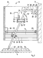
- Figures 1 and 2 show a test device with two moving Test heads, which is of essentially known design.
- a frame with base plate 1 and two cheeks 2 takes on the Base plate 1 with schematically indicated brackets 3 one testing circuit board 4.
- the Printed circuit board 4 with a number of ICs or other components equipped.
- the carriages 7, 7 ' by appropriate control of the motors 9, 9 ', 10, 10' can be moved to any point on the circuit board 4.
- the carriage 7, 7 ' carries a head drive 11 for one at the end Needle 13 arranged prehead.
- a height drive is provided with which the needles 13 are raised and can be lowered.
- Test fixtures Lines from the test heads to an electronic, not shown Test fixtures are designed to simplify the drawing because just like the electronic test device omitted.
- the circuit board 4 can be of two types, for example electrical nodes can be contacted and it can for example the volume resistance can be determined.
- test device shown is usually with more test heads equipped.
- more than two crossbars can be used and several slides can be provided on each of them, so that a large number of test heads can be used.
- test speed i.e. the average travel speed of a test head between two positions to be approached on the To significantly reduce printed circuit board 4 are the top drives 11 intended. This is explained in detail with reference to FIGS. 3 and 4.
- the head drive 11 is formed in a housing shaft 12, in the interior of which drives for the needle 13 are provided which carries a contact tip 32 at its lower end as a test head.
- Each of the slides 15 and 17 carries a gimbal in the form of a rotatable on all sides in a ball recess of the slide stored ball 24 and 25.
- the needle 13 passes through one Bore of the ball 24 or 25 longitudinally displaceable.
- the needle 13 By adjusting the slides 15 and 17 by means of the motors 18 and 19 in the X and Y directions, the needle 13 can in any Swivel positions are brought. It is in the gimbals the balls 24, 25 longitudinally displaceable. A height drive ensures Height adjustment.
- the height drive has one in the illustrated embodiment on the housing shaft 12 mounted motor 26 on his Output shaft 27 pivots an arm 28 in the direction of the arrow (FIG. 3).
- a pivot arm 30 is on the arm 28 via a pivot bearing 29 stored on which the upper end of the needle 13 with a ring slide bearing 31 shown is guided.
- the height drive shown must take into account the swivel position of the needle. This can be done through a appropriate computer control of the intended for the height drive Motors 26 take into account the respective Position of the carriages 15 pivoting in the X and Y directions and 17th
- the needle 13 with its contact tip 32 connecting legs 33 of an IC 34 start up one after the other, which are soldered to the printed circuit board 4.
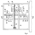
- FIGS. 5 and 6 show a basic embodiment variant, in which several of those shown in Figures 3 and 4 Head drives 11, in the embodiment six pieces in fixed arrangement attached to each other and over a to be tested Printed circuit board 35 with holders, not shown.
- the illustrated six head drives 11 for those formed on needles 13 Pre-heads are firmly above the during the test process Circuit board 35. It only move with those on the figures 3 and 4 explained drives the needles 13, so that all too contacting points on the circuit board 35 can be reached can.
- Such a solution is particularly suitable for smaller ones Circuit boards.
- a line from several next to each other arranged head drives 11, as in Figure 6 of the Side seen as a line on one of the crossbars 6, 6 'of the test device of Figures 1 and 2 may be arranged.
- this line of head drives over the PCB 4 are moved.
- FIGS. 3 and 4 Head drive 11 has a height drive, which the needle 13 as Whole height adjusted.
- a needle can be used 43 carry a height drive 44 which the contact tip 45 in the direction of the arrow adjusted relative to the needle 43.
- This allows through Reduction of the height-moving masses of the height drive significantly be accelerated. It also becomes the one in FIGS. 3 and 4 illustrated structure simplified, since the height drive shown there not applicable.
- the needle 13 then no longer has to be in both universal joints, So in both balls 24 and 25, held longitudinally his. It can be held in a longitudinally fixed manner in one of the balls.
- Figure 8 shows a further variant for the height drive.
- the needle As in FIGS. 3 and 4, 13 is longitudinally displaceable in the balls 24 and 25 out. It is from its top end height-driven, but with a different drive type than in the Figures 3 and 4 shown.
- a head 47 is at the upper end of the needle 13 supported with a helical spring 48 with respect to the slide 17 and pushes the needle 13 up.
- On the head 47 acts from above a height adjustable in parallel by a drive member 49 Plate 50, the height adjustment against the force of the spring 48 the needle 13 concerned.
- the plate 50 can have an ellipsoidal dome shape on its underside Have recess 51 which fits in two radii to the distance around the ball 24 or 25 is formed. Thereby can the computing effort for the control of the height drive motor Reduce 26.
- the head drive each designed as a needle swivel drive for the test head.
- FIG. 6 shows, for example, this has the advantage that the test head at the lower end of the needle 13 over the base of the respective head drive 11, that is, between adjacent ones Head drives overlapping, can be adjusted. If you compare Figure 2, it can be seen that the two head drives 11 laterally can be driven side by side and overlap in the border area can work.
- Needle swivel drives can also be other than those shown Drives are used.
- the needle swiveled around a central pivot point with suitable drives become.
- carriage 15 and 17 for example at the location of Sliding ring 31, that is, at its upper end, on a stationary Point be pivoted.
- the sled 15 and 17 can then the needle with slits extending parallel to its rails grasp.
- the electrical connections the contact tip 32 are omitted. This is through the needle 13 electrically connected through to a connecting conductor 52, which to an electronic test device, not shown leads. Depending on the test situation, the contact tip 32 can also be in this position a measuring amplifier or a stimulus source, e.g. a constant voltage source or a constant current source become.
- a measuring amplifier or a stimulus source e.g. a constant voltage source or a constant current source become.
- the corresponding test procedure is based on the corresponding extensive literature referenced. For example, Guard tests or parasitic transistor tests according to DE 41 10 551 C1 become.
- the needle 13 shown in the embodiments can be used instead the illustrated contact tip 32, which is used for electrical contacting is also used to carry other preheads, such as inductively or capacitive sensors, which in the example of FIG not to contact the legs 33, but at a defined distance to be brought to them.
- preheads for example optical devices, such as cameras or microscopes with connected video camera, be provided with which high-resolution considerations are made. Such facilities can in particular in miniaturized form for testing integrated circuits can be used on wafers.
- test head drives can also be used as head drives
- other mechanical drives can be provided.
- simple XY drives with the X drive on the Y drive sits, usable with which, for example, a needle-shaped Test probe is moved in parallel. They are also on one level Swiveling drives are superimposed parallel to the circuit board to be tested usable.
- test device explained with reference to FIGS. 1 to 4 can be supplemented by an additional coarse height drive the head drives 11 are held on the carriage 7, 7 '. It can be slow height drives that are only for Special cases are used when, for example, unusual height movements required when driving over a larger component are not of the height drives in the head drive 11 can be achieved.
Claims (10)
- Dispositif de test de modules électroniques plats (4, 35) avec au moins un entraínement de tête (11) pouvant être positionné au-dessus d'une surface partielle d'un module afin d'assurer le déplacement direct d'une tête d'essai (32, 45), caractérisé en ce que la tête d'essai (32, 45) peut, sans changement de position de l'entraínement de tête (11), être déplacée par celui-ci sur la totalité de la surface partielle.
- Dispositif de test selon la revendication 1, caractérisé en ce que la surface partielle est configurée de façon à recouvrir les emplacements des composantes (34).
- Dispositif de test selon la revendication 1, caractérisé en ce que plusieurs entraínements de tête (11) avec leurs têtes d'essai (32, 45) sont agencés de façon à couvrir des surfaces partielles contiguës.
- Dispositif de test selon la revendication 1, caractérisé en ce que l'entraínement de tête (11) est agencé de façon à pouvoir être positionné en surface par des éléments moteurs (7, 7') d'un entraínement principal.
- Dispositif de test selon la revendication 1, caractérisé en ce que la tête d'essai (32, 45) est disposée à l'extrémité avant d'une aiguille allongée (13, 43) maintenue par l'entraínement de tête (11) de façon à pouvoir la faire pivoter en variant l'angle qu'elle forme avec la surface du module électronique.
- Dispositif de test selon la revendication 5, caractérisé en ce que l'entraínement de tête (11) présente deux entraíneurs transversaux (15, 17) placés à différentes distances de la surface du module électronique et déplaçables parallèlement à celle-ci selon différentes directions (X, Y), et à chacun desquels l'aiguille (13) est maintenue par un logement de type Cardan avec une possibilité de déplacement longitudinal au niveau d'au moins un palier de Cardan (24, 25).
- Dispositif de test selon la revendication 5 muni d'un organe de déplacement en hauteur de la tête d'essai (32, 45) par rapport à la surface du module électronique, caractérisé en ce que la tête d'essai (32, 45) est ajustable dans le sens longitudinal de l'aiguille (13, 43) par l'organe de déplacement en hauteur (26, 44).
- Dispositif de test selon les revendications 6 et 7, caractérisé en ce que l'aiguille (13) est logée de façon à pouvoir être décalée longitudinalement dans les deux paliers de Cardan, et est actionnée à son extrémité arrière opposée à la tête d'essai (32, 45) par l'organe de déplacement en hauteur (26, 44) qui assure l'ajustage longitudinal global de l'aiguille (13).
- Dispositif de test selon la revendication 7, caractérisé en ce que la tête d'essai (45) peut être déplacée longitudinalement par rapport à l'aiguille (43) par l'organe de déplacement en hauteur (44) de l'aiguille (43).
- Dispositif de test selon la revendication 1, caractérisé en ce que qu'il comporte plusieurs entraínements de tête (11) avec différentes résolutions spatiales.
Applications Claiming Priority (3)
| Application Number | Priority Date | Filing Date | Title |
|---|---|---|---|
| DE19503329A DE19503329C2 (de) | 1995-02-02 | 1995-02-02 | Testvorrichtung für elektronische Flachbaugruppen |
| DE19503329 | 1995-02-02 | ||
| PCT/EP1996/000280 WO1996024069A1 (fr) | 1995-02-02 | 1996-01-24 | Appareil de controle pour ensembles electroniques plats |
Publications (2)
| Publication Number | Publication Date |
|---|---|
| EP0807258A1 EP0807258A1 (fr) | 1997-11-19 |
| EP0807258B1 true EP0807258B1 (fr) | 2000-01-19 |
Family
ID=7752974
Family Applications (1)
| Application Number | Title | Priority Date | Filing Date |
|---|---|---|---|
| EP96902914A Expired - Lifetime EP0807258B1 (fr) | 1995-02-02 | 1996-01-24 | Appareil de controle pour ensembles electroniques plats |
Country Status (9)
| Country | Link |
|---|---|
| US (1) | US6307389B1 (fr) |
| EP (1) | EP0807258B1 (fr) |
| JP (1) | JPH10513261A (fr) |
| AT (1) | ATE189064T1 (fr) |
| AU (1) | AU4713796A (fr) |
| CA (1) | CA2211703C (fr) |
| DE (2) | DE19503329C2 (fr) |
| DK (1) | DK0807258T3 (fr) |
| WO (1) | WO1996024069A1 (fr) |
Cited By (1)
| Publication number | Priority date | Publication date | Assignee | Title |
|---|---|---|---|---|
| DE202012101557U1 (de) | 2012-04-26 | 2012-05-10 | MPH Mess-, Prüf- und Handling-Systeme GmbH | Testvorrichtung |
Families Citing this family (23)
| Publication number | Priority date | Publication date | Assignee | Title |
|---|---|---|---|---|
| DE19709939A1 (de) * | 1997-03-11 | 1998-09-17 | Atg Test Systems Gmbh | Verfahren und Vorrichtung zum Prüfen von Leiterplatten |
| DE20005123U1 (de) * | 2000-03-20 | 2001-08-02 | Atg Test Systems Gmbh | Vorrichtung zum Prüfen von Leiterplatten |
| WO2002008773A2 (fr) * | 2000-07-19 | 2002-01-31 | Orbotech Ltd. | Appareil et procede destines a des tests electriques sur des circuits electriques |
| DE10042770C1 (de) * | 2000-08-31 | 2002-04-04 | Miele & Cie | Verfahren zur Hochspannungsprüfung bei einem elektrischen Gerät, insbesondere bei einem Staubsauger |
| US6657449B2 (en) * | 2000-12-21 | 2003-12-02 | Hansaem Digitec Co., Ltd. | Test pin unit for PCB test device and feeding device of the same |
| DE10159165B4 (de) * | 2001-12-03 | 2007-02-08 | Agilent Technologies, Inc. (n.d.Ges.d.Staates Delaware), Palo Alto | Vorrichtung zum Messen und/oder Kalibrieren eines Testkopfes |
| DE10160119A1 (de) | 2001-12-07 | 2003-10-02 | Atg Test Systems Gmbh | Prüfsonde für einen Fingertester |
| US6822463B1 (en) | 2001-12-21 | 2004-11-23 | Lecroy Corporation | Active differential test probe with a transmission line input structure |
| DE10320381B4 (de) * | 2003-05-06 | 2010-11-04 | Scorpion Technologies Ag | Platinentestvorrichtung mit schrägstehend angetriebenen Kontaktiernadeln |
| US20050174139A1 (en) * | 2003-10-14 | 2005-08-11 | Mahendran Chidambaram | Apparatus for high speed probing of flat panel displays |
| JP5024740B2 (ja) * | 2004-09-30 | 2012-09-12 | 学校法人慶應義塾 | Lsiチップ試験装置 |
| US7463042B2 (en) * | 2005-06-30 | 2008-12-09 | Northrop Grumman Corporation | Connector probing system |
| US8134377B1 (en) | 2005-08-31 | 2012-03-13 | Lecroy Corporation | Adherable holder and locater tool |
| US7256596B1 (en) * | 2005-11-01 | 2007-08-14 | Russell Robert J | Method and apparatus for adapting a standard flying prober system for reliable testing of printed circuit assemblies |
| DE102006021569A1 (de) | 2006-02-09 | 2007-08-16 | Rohde & Schwarz Gmbh & Co. Kg | Prüfsystem für einen Schaltungsträger |
| US8674714B2 (en) * | 2007-06-29 | 2014-03-18 | PPI Systems, Inc. | System and method for probing work pieces |
| TWI381168B (zh) * | 2009-09-02 | 2013-01-01 | Au Optronics Mfg Shanghai Corp | 通用探針模組 |
| DE102010053766B4 (de) | 2010-12-08 | 2019-05-23 | Acculogic Corporation | Vorrichtung zum thermischen Testen von Platinen |
| CN104969080B (zh) * | 2012-11-21 | 2019-02-15 | 康拉德有限责任公司 | 用于测试工件的方法及装置 |
| DE102013102564A1 (de) * | 2013-03-13 | 2014-09-18 | Dtg International Gmbh | Traverseneinheit für eine Prüfvorrichtung für Leiterplatten, sowie Prüfvorrichtung damit |
| CN104597381B (zh) * | 2015-01-20 | 2017-10-31 | 厦门大学 | 电连接器机械性能与电气安全性能的检测装置与检测方法 |
| US11255877B2 (en) | 2020-07-17 | 2022-02-22 | Acculogic Corporation | Method and apparatus for testing printed circuit boards |
| US20230288475A1 (en) * | 2020-08-14 | 2023-09-14 | Jenoptik Optical Systems Gmbh | Contacting module for having a mounting plate for contacting optoelectronic chips |
Family Cites Families (5)
| Publication number | Priority date | Publication date | Assignee | Title |
|---|---|---|---|---|
| US3185927A (en) * | 1961-01-31 | 1965-05-25 | Kulicke & Soffa Mfg Co | Probe instrument for inspecting semiconductor wafers including means for marking defective zones |
| US5107206A (en) * | 1990-05-25 | 1992-04-21 | Tescon Co., Ltd. | Printed circuit board inspection apparatus |
| DE4109684C2 (de) * | 1990-07-25 | 2001-07-12 | Atg Test Systems Gmbh | Kontaktierungsvorrichtung für Prüfzwecke |
| EP0468153B1 (fr) * | 1990-07-25 | 1995-10-11 | atg test systems GmbH | Dispositif pour contacter des éléments à tester |
| KR0176627B1 (ko) * | 1995-12-30 | 1999-05-15 | 김광호 | 인쇄회로기판의 통전검사용 프로브 장치 |
-
1995
- 1995-02-02 DE DE19503329A patent/DE19503329C2/de not_active Expired - Fee Related
-
1996
- 1996-01-24 AU AU47137/96A patent/AU4713796A/en not_active Abandoned
- 1996-01-24 CA CA002211703A patent/CA2211703C/fr not_active Expired - Lifetime
- 1996-01-24 DE DE59604229T patent/DE59604229D1/de not_active Expired - Lifetime
- 1996-01-24 DK DK96902914T patent/DK0807258T3/da active
- 1996-01-24 EP EP96902914A patent/EP0807258B1/fr not_active Expired - Lifetime
- 1996-01-24 JP JP8523220A patent/JPH10513261A/ja not_active Ceased
- 1996-01-24 US US08/875,666 patent/US6307389B1/en not_active Expired - Lifetime
- 1996-01-24 AT AT96902914T patent/ATE189064T1/de active
- 1996-01-24 WO PCT/EP1996/000280 patent/WO1996024069A1/fr active IP Right Grant
Cited By (1)
| Publication number | Priority date | Publication date | Assignee | Title |
|---|---|---|---|---|
| DE202012101557U1 (de) | 2012-04-26 | 2012-05-10 | MPH Mess-, Prüf- und Handling-Systeme GmbH | Testvorrichtung |
Also Published As
| Publication number | Publication date |
|---|---|
| ATE189064T1 (de) | 2000-02-15 |
| AU4713796A (en) | 1996-08-21 |
| EP0807258A1 (fr) | 1997-11-19 |
| DE19503329C2 (de) | 2000-05-18 |
| US6307389B1 (en) | 2001-10-23 |
| DE19503329A1 (de) | 1996-08-08 |
| US20010028254A1 (en) | 2001-10-11 |
| WO1996024069A1 (fr) | 1996-08-08 |
| DK0807258T3 (da) | 2000-05-08 |
| CA2211703A1 (fr) | 1996-08-08 |
| DE59604229D1 (de) | 2000-02-24 |
| CA2211703C (fr) | 2002-08-06 |
| JPH10513261A (ja) | 1998-12-15 |
Similar Documents
| Publication | Publication Date | Title |
|---|---|---|
| EP0807258B1 (fr) | Appareil de controle pour ensembles electroniques plats | |
| DE10005807A1 (de) | Zweidimensionales Antriebssystem | |
| DE102013102564A1 (de) | Traverseneinheit für eine Prüfvorrichtung für Leiterplatten, sowie Prüfvorrichtung damit | |
| DE19952553B4 (de) | Kompakte Video-Prüf-Vorrichtung mit gekoppelten Y,Z, X Messachsen | |
| DE2628428C3 (de) | Adapter zum Verbinden von Anschluß- und/oder Prüfpunkten einer Baugruppe mit einer Mefischaltung | |
| DE2559004C2 (de) | Anordnung zur Prüfung von elektrischen Prüflingen mit einer Vielzahl von Prüfkontakten | |
| DE19844428B4 (de) | Prüfsonde für einen Fingertester, ein Verfahren zum Ansteuern einer Prüfsonde, Fingertester zum Prüfen von Leiterplatten und ein Verfahren zum Prüfen von Leiterplatten mit einem Fingertester | |
| DE2800775C2 (fr) | ||
| EP0424961B1 (fr) | Appareil à planter les composants | |
| DE102007037886B4 (de) | Feldgeführter planarer Präzisionsantrieb mit einem luftgelagerten Läufer | |
| EP1954115B1 (fr) | Tête à implanter multiple dotée d'un entraînement rotatif collectif et d'un entraînement d'élévation mobile pour dispositifs de retenue de composants | |
| DE19920776A1 (de) | Vorrichtung zum Positionieren einer Arbeitseinheit | |
| DE4109684A1 (de) | Kontaktierungsvorrichtung fuer pruefzwecke | |
| DE10159165B4 (de) | Vorrichtung zum Messen und/oder Kalibrieren eines Testkopfes | |
| EP3500398B1 (fr) | Dispositif d'accueil destiné à accueillir un objet de forme quelconque | |
| EP0416524B1 (fr) | Dispositif pour le changement de palpeurs pour dispositifs de mesure | |
| DE102008023614B3 (de) | Verfahren zum automatischen Positionieren von Unterstützungsstiften und Bestückautomat | |
| DE3539979A1 (de) | Mikro-manipulator | |
| DE19757567C2 (de) | Einrichtung zur Verstellung des Meßtisches an einem Meßmikroskop | |
| WO2004050310A2 (fr) | Dispositif de marquage | |
| DE102006046028B4 (de) | Verschiebeeinrichtung für eine Bauelement-Haltevorrichtung mit zentraler Krafteinleitung | |
| DE3906691A1 (de) | Kontaktiervorrichtung fuer pruefvorrichtungen zum pruefen von leiterplatten oder dgl. | |
| DE102007000306B4 (de) | Koordinatenmessvorrichtung | |
| DE102021112047A1 (de) | Verfahreinheit zum Verfahren von zwei Lötbaugruppen zur Bearbeitung von Leiterplatten und Lötanlage zum selektiven Wellenlöten mit einer Verfahreinheit | |
| DE4312909C2 (de) | Vorrichtung zur automatischen Manipulation von Werkstücken in einem kartesischen Koordinatensystem |
Legal Events
| Date | Code | Title | Description |
|---|---|---|---|
| PUAI | Public reference made under article 153(3) epc to a published international application that has entered the european phase |
Free format text: ORIGINAL CODE: 0009012 |
|
| 17P | Request for examination filed |
Effective date: 19970703 |
|
| AK | Designated contracting states |
Kind code of ref document: A1 Designated state(s): AT CH DE DK FR GB IT LI NL SE |
|
| 17Q | First examination report despatched |
Effective date: 19980109 |
|
| GRAG | Despatch of communication of intention to grant |
Free format text: ORIGINAL CODE: EPIDOS AGRA |
|
| GRAG | Despatch of communication of intention to grant |
Free format text: ORIGINAL CODE: EPIDOS AGRA |
|
| GRAG | Despatch of communication of intention to grant |
Free format text: ORIGINAL CODE: EPIDOS AGRA |
|
| GRAH | Despatch of communication of intention to grant a patent |
Free format text: ORIGINAL CODE: EPIDOS IGRA |
|
| GRAH | Despatch of communication of intention to grant a patent |
Free format text: ORIGINAL CODE: EPIDOS IGRA |
|
| RAP1 | Party data changed (applicant data changed or rights of an application transferred) |
Owner name: ITA INGENIEURBUERO FUER TESTAUFGABEN GMBH |
|
| GRAA | (expected) grant |
Free format text: ORIGINAL CODE: 0009210 |
|
| AK | Designated contracting states |
Kind code of ref document: B1 Designated state(s): AT CH DE DK FR GB IT LI NL SE |
|
| REF | Corresponds to: |
Ref document number: 189064 Country of ref document: AT Date of ref document: 20000215 Kind code of ref document: T |
|
| REG | Reference to a national code |
Ref country code: CH Ref legal event code: NV Representative=s name: WILLIAM BLANC & CIE CONSEILS EN PROPRIETE INDUSTRI Ref country code: CH Ref legal event code: EP |
|
| ITF | It: translation for a ep patent filed |
Owner name: BUGNION S.P.A. |
|
| REF | Corresponds to: |
Ref document number: 59604229 Country of ref document: DE Date of ref document: 20000224 |
|
| GBT | Gb: translation of ep patent filed (gb section 77(6)(a)/1977) |
Effective date: 20000208 |
|
| ET | Fr: translation filed | ||
| REG | Reference to a national code |
Ref country code: DK Ref legal event code: T3 |
|
| REG | Reference to a national code |
Ref country code: CH Ref legal event code: PFA Free format text: ITA INGENIEURBUERO FUER TESTAUFGABEN GMBH TRANSFER- SCORPION TECHNOLOGIES AG |
|
| REG | Reference to a national code |
Ref country code: FR Ref legal event code: CJ Ref country code: FR Ref legal event code: CD |
|
| PLBE | No opposition filed within time limit |
Free format text: ORIGINAL CODE: 0009261 |
|
| STAA | Information on the status of an ep patent application or granted ep patent |
Free format text: STATUS: NO OPPOSITION FILED WITHIN TIME LIMIT |
|
| NLS | Nl: assignments of ep-patents |
Owner name: SCORPION TECHNOLOGIES AG |
|
| 26N | No opposition filed | ||
| REG | Reference to a national code |
Ref country code: GB Ref legal event code: IF02 |
|
| PGFP | Annual fee paid to national office [announced via postgrant information from national office to epo] |
Ref country code: DK Payment date: 20090113 Year of fee payment: 14 |
|
| PGFP | Annual fee paid to national office [announced via postgrant information from national office to epo] |
Ref country code: FR Payment date: 20090113 Year of fee payment: 14 |
|
| REG | Reference to a national code |
Ref country code: CH Ref legal event code: PFA Owner name: SCORPION TECHNOLOGIES AG Free format text: SCORPION TECHNOLOGIES AG#PAPENREYE 51#22453 HAMBURG (DE) -TRANSFER TO- SCORPION TECHNOLOGIES AG#PAPENREYE 51#22453 HAMBURG (DE) |
|
| REG | Reference to a national code |
Ref country code: DK Ref legal event code: EBP |
|
| REG | Reference to a national code |
Ref country code: FR Ref legal event code: ST Effective date: 20100930 |
|
| PG25 | Lapsed in a contracting state [announced via postgrant information from national office to epo] |
Ref country code: FR Free format text: LAPSE BECAUSE OF NON-PAYMENT OF DUE FEES Effective date: 20100201 |
|
| PG25 | Lapsed in a contracting state [announced via postgrant information from national office to epo] |
Ref country code: DK Free format text: LAPSE BECAUSE OF NON-PAYMENT OF DUE FEES Effective date: 20100131 |
|
| REG | Reference to a national code |
Ref country code: CH Ref legal event code: PCAR Free format text: NOVAGRAAF SWITZERLAND SA;CHEMIN DE L'ECHO 3;1213 ONEX (CH) |
|
| PGFP | Annual fee paid to national office [announced via postgrant information from national office to epo] |
Ref country code: NL Payment date: 20140110 Year of fee payment: 19 |
|
| PGFP | Annual fee paid to national office [announced via postgrant information from national office to epo] |
Ref country code: CH Payment date: 20150114 Year of fee payment: 20 Ref country code: IT Payment date: 20150114 Year of fee payment: 20 Ref country code: DE Payment date: 20141023 Year of fee payment: 20 |
|
| PGFP | Annual fee paid to national office [announced via postgrant information from national office to epo] |
Ref country code: AT Payment date: 20141222 Year of fee payment: 20 Ref country code: GB Payment date: 20150121 Year of fee payment: 20 Ref country code: SE Payment date: 20150113 Year of fee payment: 20 |
|
| REG | Reference to a national code |
Ref country code: NL Ref legal event code: V1 Effective date: 20150801 |
|
| PG25 | Lapsed in a contracting state [announced via postgrant information from national office to epo] |
Ref country code: NL Free format text: LAPSE BECAUSE OF NON-PAYMENT OF DUE FEES Effective date: 20150801 |
|
| REG | Reference to a national code |
Ref country code: DE Ref legal event code: R071 Ref document number: 59604229 Country of ref document: DE |
|
| REG | Reference to a national code |
Ref country code: CH Ref legal event code: PL |
|
| REG | Reference to a national code |
Ref country code: GB Ref legal event code: PE20 Expiry date: 20160123 |
|
| REG | Reference to a national code |
Ref country code: SE Ref legal event code: EUG |
|
| REG | Reference to a national code |
Ref country code: AT Ref legal event code: MK07 Ref document number: 189064 Country of ref document: AT Kind code of ref document: T Effective date: 20160124 |
|
| PG25 | Lapsed in a contracting state [announced via postgrant information from national office to epo] |
Ref country code: GB Free format text: LAPSE BECAUSE OF EXPIRATION OF PROTECTION Effective date: 20160123 |