EP0807258B1 - Test device for flat electronic assemblies - Google Patents
Test device for flat electronic assemblies Download PDFInfo
- Publication number
- EP0807258B1 EP0807258B1 EP96902914A EP96902914A EP0807258B1 EP 0807258 B1 EP0807258 B1 EP 0807258B1 EP 96902914 A EP96902914 A EP 96902914A EP 96902914 A EP96902914 A EP 96902914A EP 0807258 B1 EP0807258 B1 EP 0807258B1
- Authority
- EP
- European Patent Office
- Prior art keywords
- probe
- drive
- needle
- drives
- test device
- Prior art date
- Legal status (The legal status is an assumption and is not a legal conclusion. Google has not performed a legal analysis and makes no representation as to the accuracy of the status listed.)
- Expired - Lifetime
Links
- 238000012360 testing method Methods 0.000 title claims abstract description 101
- 230000000712 assembly Effects 0.000 title claims description 4
- 238000000429 assembly Methods 0.000 title claims description 4
- 239000000523 sample Substances 0.000 claims abstract description 34
- 238000006073 displacement reaction Methods 0.000 claims 1
- 238000010276 construction Methods 0.000 description 5
- 238000013461 design Methods 0.000 description 4
- 230000001965 increasing effect Effects 0.000 description 4
- 238000004519 manufacturing process Methods 0.000 description 3
- 230000003287 optical effect Effects 0.000 description 3
- 238000013459 approach Methods 0.000 description 2
- 238000000034 method Methods 0.000 description 2
- 239000007921 spray Substances 0.000 description 2
- 238000010998 test method Methods 0.000 description 2
- 235000012431 wafers Nutrition 0.000 description 2
- JAYCNKDKIKZTAF-UHFFFAOYSA-N 1-chloro-2-(2-chlorophenyl)benzene Chemical compound ClC1=CC=CC=C1C1=CC=CC=C1Cl JAYCNKDKIKZTAF-UHFFFAOYSA-N 0.000 description 1
- 101100084627 Neurospora crassa (strain ATCC 24698 / 74-OR23-1A / CBS 708.71 / DSM 1257 / FGSC 987) pcb-4 gene Proteins 0.000 description 1
- 230000001133 acceleration Effects 0.000 description 1
- 239000000969 carrier Substances 0.000 description 1
- 239000004020 conductor Substances 0.000 description 1
- 230000001939 inductive effect Effects 0.000 description 1
- 238000005457 optimization Methods 0.000 description 1
- 230000003071 parasitic effect Effects 0.000 description 1
- 238000010079 rubber tapping Methods 0.000 description 1
- 238000012549 training Methods 0.000 description 1
Images


Classifications
-
- G—PHYSICS
- G01—MEASURING; TESTING
- G01R—MEASURING ELECTRIC VARIABLES; MEASURING MAGNETIC VARIABLES
- G01R1/00—Details of instruments or arrangements of the types included in groups G01R5/00 - G01R13/00 and G01R31/00
- G01R1/02—General constructional details
- G01R1/06—Measuring leads; Measuring probes
- G01R1/067—Measuring probes
- G01R1/06705—Apparatus for holding or moving single probes
-
- G—PHYSICS
- G01—MEASURING; TESTING
- G01R—MEASURING ELECTRIC VARIABLES; MEASURING MAGNETIC VARIABLES
- G01R1/00—Details of instruments or arrangements of the types included in groups G01R5/00 - G01R13/00 and G01R31/00
- G01R1/02—General constructional details
- G01R1/06—Measuring leads; Measuring probes
- G01R1/067—Measuring probes
- G01R1/073—Multiple probes
- G01R1/07392—Multiple probes manipulating each probe element or tip individually
Definitions
- the invention relates to a test device in the preamble of claim 1 Art.
- test devices are used to check electronic printed circuit boards of various types. Such assemblies can, for example assembled or bare circuit boards or for example on a wafer arranged into several highly integrated circuits for IC production.
- the test heads can be of various types, such as electrical Contact peaks via relay fields on stimulus sources or measuring amplifiers a suitable electronic measuring device can be connected or other test heads used for other test methods, such as inductive or capacitive sensors or optical scanners, for example cameras or microscopes.
- test heads For quick testing of larger printed circuit boards, such as computer motherboards, usually several test heads are provided, which are independent of each other are positionable. This is often the reason why several test heads are used required to connect multiple electrical nodes at the same time for example, to apply a voltage at two nodes and on tapping a voltage at a third node.
- the control of the test heads mostly takes place on the basis of sequence programs, which are individual for one certain printed circuit boards are created.
- test devices of this type are always designed in such a way that all preheads over the entire area of the maximum still on of the test device, the testable flat module can be positioned.
- the test heads are arranged on slides, with spindles in the X and Y directions over the surface of the Flat module are movable.
- moving up and down Contact tips are height drives working on the slides in the Z direction intended.
- the slide guides and drives over the entire length of the printed circuit board to be tested be movable, that is over considerable lengths, which at a typical PC circuit board, for example, 30 x 40 cm.
- a typical PC circuit board for example, 30 x 40 cm.
- the individual contact pins modern ICs with a length resolution far below 1/10 mm can be controlled. Therefore, they are extremely stable and heavy bearings and drives are required for the sledges lead to high moving masses.
- test devices of the generic type are kind of too slow. It can therefore only be selected individually Printed circuit boards are tested or several test devices are required can be used in parallel.
- test fixtures for each grid point on the printed circuit board have their own test head, that is, with stationary ones Probes work and the speed problems mentioned do not to have.
- these test devices are circuit-wise and inexpensive disadvantageous and especially with regard to their fixed arrangement of the test specimens. she are therefore only suitable for a certain, mass-produced flat module, while the generic test devices with their movable Test heads suitable for rapid changeover to various printed circuit boards for testing small series.
- each carry a head drive in the form of a swivel lever, at the end of a height-adjustable head can be provided.
- the head drive For positioning the test head can the head drive by pivoting the swivel arm be used. However, this only allows points to be placed on a circle around the Reach sled. Should all surface points of the PCB be accessible must be both the head drive and the for positioning the test head Carriage drive and the drive of the movable crossbar can be operated. If the test head is adjusted quickly, the light head drive is not sufficient to operate, but there must be heavy sledges and crossbars are operated, i.e. large masses are accelerated. This construction does not offer any speed advantages compared to the previously cited general State of the art.
- Head drives are known from US-A-3 185 927 and EP-A-0 458 280 which the test head sits at the end of a needle that can be controlled by pivoting.
- the object of the present invention is to provide a test device to create the type mentioned above with higher test speed.
- test devices With this design, the advantage of the test devices mentioned at the outset remains received, even a larger flat module with only one or with a few movable To be able to test probes. Compared to those known in this field
- the advantage of test devices is that one test head can be used by one Head drive driven over only a partial area of the total area of the printed circuit board becomes. This shortens the routes and allows you to do the same or better control precision the moving masses by orders of magnitude be reduced. This results in an order of magnitude which can be increased accordingly Driving speed. For certain applications, e.g. a big PCB with only one IC, it is sufficient to provide the partial area in the size of the IC. The remaining few test points on the board can be tested in other ways become.
- test heads with corresponding sub-areas
- the head drives can be between different sub-areas the flat module can be moved or several, covering the entire area, be fixed provided.
- Equipped electronic circuit boards the most common test case nowadays mostly equipped with ICs of standardized size. are the sub-areas adapted to the ICs, it is sufficient to use head drives to be positioned over all ICs or one or more head drives to move from IC to IC in order to reach all those to be reached To be able to approach test points.
- head drives can be arranged in one line be and by a main drive one after the other across Move the direction of the line over a larger board. It head drives can also cover the entire area of a device under test Assembly covering be arranged stionär, which is particularly for Smaller assemblies to be tested can be an advantage. With the latter Training is very high, so far unthinkable test speeds reachable.
- Head drives can instead of known test devices on the sled of the pre-arranged heads previously provided and are moved in larger steps by the main drives. Even if the main drives, as is common in the prior art, are very slow, this slows down the overall test time not essential, since with an optimized test sequence program for it can be ensured that the main drive is only a few steps makes the much larger number of test steps from the very fast head drives is made.
- test head is arranged on a swiveling needle, so it can also adjusted beyond the base of the head drive become.
- head drives can be arranged adjacent where the test heads are in the border area of two head drives can work overlapping.
- Part-turn actuators can be current state of the art for the required control electronics train very easily and quickly. They offer the extra Advantage, places difficult to access with an inclined needle to be able to reach, for example, those that are only on the side, but are not directly accessible from above.
- Test heads can be optical, capacitive or other, for example Work in a contactless manner, keeping the distance to the test object Surface location of the printed circuit board is not critical. Then a height drive would not be necessary for the pre-spray head. At least with electrically contacting, designed as a contact tip However, a height drive is required for the test heads, which is the contact tip drop off at each test point and lift again. At Such test devices are advantageous in the features of the claim 7 provided. By moving the contact tip opposite the head drive also results for this drive very low masses and high positioning speeds.
- the features of claim 8 are advantageously provided. As a result, the needle is very easily movable as a whole.
- the contact tip compared to the Needle are moved. This makes the needle more mechanically complex, however the moving masses are further reduced.
- the features of claim 10 are advantageously provided. This creates a large number of possible variations for speed optimization. For example, has an assembled circuit board some highly integrated ICs with a very narrow grid of contacts Connection pins on, but otherwise for example one Number of discrete blocks with a coarser grid, so small areas Working head drives of the highest resolution for starting of the ICs and low-resolution head drives for Approach the other contact points. For these other contact points can even from slow main drives, for example movable test heads can be used.
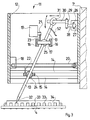
- Figures 1 and 2 show a test device with two moving Test heads, which is of essentially known design.
- a frame with base plate 1 and two cheeks 2 takes on the Base plate 1 with schematically indicated brackets 3 one testing circuit board 4.
- the Printed circuit board 4 with a number of ICs or other components equipped.
- the carriages 7, 7 ' by appropriate control of the motors 9, 9 ', 10, 10' can be moved to any point on the circuit board 4.
- the carriage 7, 7 ' carries a head drive 11 for one at the end Needle 13 arranged prehead.
- a height drive is provided with which the needles 13 are raised and can be lowered.
- Test fixtures Lines from the test heads to an electronic, not shown Test fixtures are designed to simplify the drawing because just like the electronic test device omitted.
- the circuit board 4 can be of two types, for example electrical nodes can be contacted and it can for example the volume resistance can be determined.
- test device shown is usually with more test heads equipped.
- more than two crossbars can be used and several slides can be provided on each of them, so that a large number of test heads can be used.
- test speed i.e. the average travel speed of a test head between two positions to be approached on the To significantly reduce printed circuit board 4 are the top drives 11 intended. This is explained in detail with reference to FIGS. 3 and 4.
- the head drive 11 is formed in a housing shaft 12, in the interior of which drives for the needle 13 are provided which carries a contact tip 32 at its lower end as a test head.
- Each of the slides 15 and 17 carries a gimbal in the form of a rotatable on all sides in a ball recess of the slide stored ball 24 and 25.
- the needle 13 passes through one Bore of the ball 24 or 25 longitudinally displaceable.
- the needle 13 By adjusting the slides 15 and 17 by means of the motors 18 and 19 in the X and Y directions, the needle 13 can in any Swivel positions are brought. It is in the gimbals the balls 24, 25 longitudinally displaceable. A height drive ensures Height adjustment.
- the height drive has one in the illustrated embodiment on the housing shaft 12 mounted motor 26 on his Output shaft 27 pivots an arm 28 in the direction of the arrow (FIG. 3).
- a pivot arm 30 is on the arm 28 via a pivot bearing 29 stored on which the upper end of the needle 13 with a ring slide bearing 31 shown is guided.
- the height drive shown must take into account the swivel position of the needle. This can be done through a appropriate computer control of the intended for the height drive Motors 26 take into account the respective Position of the carriages 15 pivoting in the X and Y directions and 17th
- the needle 13 with its contact tip 32 connecting legs 33 of an IC 34 start up one after the other, which are soldered to the printed circuit board 4.
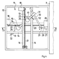
- FIGS. 5 and 6 show a basic embodiment variant, in which several of those shown in Figures 3 and 4 Head drives 11, in the embodiment six pieces in fixed arrangement attached to each other and over a to be tested Printed circuit board 35 with holders, not shown.
- the illustrated six head drives 11 for those formed on needles 13 Pre-heads are firmly above the during the test process Circuit board 35. It only move with those on the figures 3 and 4 explained drives the needles 13, so that all too contacting points on the circuit board 35 can be reached can.
- Such a solution is particularly suitable for smaller ones Circuit boards.
- a line from several next to each other arranged head drives 11, as in Figure 6 of the Side seen as a line on one of the crossbars 6, 6 'of the test device of Figures 1 and 2 may be arranged.
- this line of head drives over the PCB 4 are moved.
- FIGS. 3 and 4 Head drive 11 has a height drive, which the needle 13 as Whole height adjusted.
- a needle can be used 43 carry a height drive 44 which the contact tip 45 in the direction of the arrow adjusted relative to the needle 43.
- This allows through Reduction of the height-moving masses of the height drive significantly be accelerated. It also becomes the one in FIGS. 3 and 4 illustrated structure simplified, since the height drive shown there not applicable.
- the needle 13 then no longer has to be in both universal joints, So in both balls 24 and 25, held longitudinally his. It can be held in a longitudinally fixed manner in one of the balls.
- Figure 8 shows a further variant for the height drive.
- the needle As in FIGS. 3 and 4, 13 is longitudinally displaceable in the balls 24 and 25 out. It is from its top end height-driven, but with a different drive type than in the Figures 3 and 4 shown.
- a head 47 is at the upper end of the needle 13 supported with a helical spring 48 with respect to the slide 17 and pushes the needle 13 up.
- On the head 47 acts from above a height adjustable in parallel by a drive member 49 Plate 50, the height adjustment against the force of the spring 48 the needle 13 concerned.
- the plate 50 can have an ellipsoidal dome shape on its underside Have recess 51 which fits in two radii to the distance around the ball 24 or 25 is formed. Thereby can the computing effort for the control of the height drive motor Reduce 26.
- the head drive each designed as a needle swivel drive for the test head.
- FIG. 6 shows, for example, this has the advantage that the test head at the lower end of the needle 13 over the base of the respective head drive 11, that is, between adjacent ones Head drives overlapping, can be adjusted. If you compare Figure 2, it can be seen that the two head drives 11 laterally can be driven side by side and overlap in the border area can work.
- Needle swivel drives can also be other than those shown Drives are used.
- the needle swiveled around a central pivot point with suitable drives become.
- carriage 15 and 17 for example at the location of Sliding ring 31, that is, at its upper end, on a stationary Point be pivoted.
- the sled 15 and 17 can then the needle with slits extending parallel to its rails grasp.
- the electrical connections the contact tip 32 are omitted. This is through the needle 13 electrically connected through to a connecting conductor 52, which to an electronic test device, not shown leads. Depending on the test situation, the contact tip 32 can also be in this position a measuring amplifier or a stimulus source, e.g. a constant voltage source or a constant current source become.
- a measuring amplifier or a stimulus source e.g. a constant voltage source or a constant current source become.
- the corresponding test procedure is based on the corresponding extensive literature referenced. For example, Guard tests or parasitic transistor tests according to DE 41 10 551 C1 become.
- the needle 13 shown in the embodiments can be used instead the illustrated contact tip 32, which is used for electrical contacting is also used to carry other preheads, such as inductively or capacitive sensors, which in the example of FIG not to contact the legs 33, but at a defined distance to be brought to them.
- preheads for example optical devices, such as cameras or microscopes with connected video camera, be provided with which high-resolution considerations are made. Such facilities can in particular in miniaturized form for testing integrated circuits can be used on wafers.
- test head drives can also be used as head drives
- other mechanical drives can be provided.
- simple XY drives with the X drive on the Y drive sits, usable with which, for example, a needle-shaped Test probe is moved in parallel. They are also on one level Swiveling drives are superimposed parallel to the circuit board to be tested usable.
- test device explained with reference to FIGS. 1 to 4 can be supplemented by an additional coarse height drive the head drives 11 are held on the carriage 7, 7 '. It can be slow height drives that are only for Special cases are used when, for example, unusual height movements required when driving over a larger component are not of the height drives in the head drive 11 can be achieved.
Landscapes
- Physics & Mathematics (AREA)
- General Physics & Mathematics (AREA)
- Tests Of Electronic Circuits (AREA)
- Coupling Device And Connection With Printed Circuit (AREA)
- Measuring Leads Or Probes (AREA)
- Testing Of Individual Semiconductor Devices (AREA)
- Semiconductor Integrated Circuits (AREA)
- Testing Electric Properties And Detecting Electric Faults (AREA)
Abstract
Description
Die Erfindung betrifft eine Testvorrichtung der im Oberbegriff des Anspruchs 1
genannten Art.The invention relates to a test device in the preamble of
Bekannte Testvorrichtungen dienen der Überprüfung elektronischer Flachbaugruppen unterschiedlichster Art. Solche Flachbaugruppen können beispielsweise bestückte oder unbestückte Leiterplatten sein oder zum Beispiel auf einem Wafer zu mehreren angeordnete hochintegrierte Schaltkreise zur IC-Herstellung. Auch die Prüfköpfe können unterschiedlichster Art sein, wie beispielsweise elektrische Kontaktspitzen, die über Relaisfelder an Stimulusquellen oder Meßverstärker einer geeigneten elektronischen Meßeinrichtung anschließbar sind oder sonstige für andere Prüfverfahren verwendete Prüfköpfe, wie beispielsweise induktive oder kapazitive Sensoren oder auch optische Abtaster, beispielsweise Kameras oder Mikroskope.Known test devices are used to check electronic printed circuit boards of various types. Such assemblies can, for example assembled or bare circuit boards or for example on a wafer arranged into several highly integrated circuits for IC production. Also the test heads can be of various types, such as electrical Contact peaks via relay fields on stimulus sources or measuring amplifiers a suitable electronic measuring device can be connected or other test heads used for other test methods, such as inductive or capacitive sensors or optical scanners, for example cameras or microscopes.
Zum schnellen Testen größerer Flachbaugruppen, wie beispielsweise Computer-Motherboards, sind meist mehrere Prüfköpfe vorgesehen, die unabhängig voneinander positionierbar sind. Mehrere Prüfköpfe sind häufig auch schon deswegen erforderlich, um bei gleichzeitigem Kontaktieren mehrerer elektrischer Knotenpunkte zum Beispiel an zwei Knotenpunkten eine Spannung anzulegen und an einem dritten Knotenpunkt eine Spannung abzugreifen. Die Steuerung der Prüfköpfe erfolgt zumeist an Hand von Ablaufprogrammnen, die individuell für eine bestimmte Flachbaugruppe erstellt werden. For quick testing of larger printed circuit boards, such as computer motherboards, usually several test heads are provided, which are independent of each other are positionable. This is often the reason why several test heads are used required to connect multiple electrical nodes at the same time for example, to apply a voltage at two nodes and on tapping a voltage at a third node. The control of the test heads mostly takes place on the basis of sequence programs, which are individual for one certain printed circuit boards are created.
Bekannte Testvorrichtungen dieser Art sind stets derart ausgebildet, daß alle Prülköpfe über die gesamte Fläche der maximal noch auf der Testvorrichtung testbaren Flachbaugruppe positionierbar sind. In üblicher Ausführung sind dabei die Prüfköpfe an Schlitten angeordnet, die mit Spindeln in X- und Y-Richtung über der Fläche der Flachbaugruppe verfahrbar sind. Im Falle auf- und abbewegbarer Kontaktspitzen sind an den Schlitten in Z-Richtung arbeitende Höhenantriebe vorgesehen.Known test devices of this type are always designed in such a way that all preheads over the entire area of the maximum still on of the test device, the testable flat module can be positioned. In the usual design, the test heads are arranged on slides, with spindles in the X and Y directions over the surface of the Flat module are movable. In the case of moving up and down Contact tips are height drives working on the slides in the Z direction intended.
Bei den bekannten Testvorrichtungen müssen die Schlittenführungen und -antriebe über die gesamte Länge der zu testenden Flachbaugruppe verfahrbar sein, also über erhebliche Längen, die bei einer typischen PC-Leiterplatte zum Beispiel 30 x 40 cm betragen. Bei diesen erheblichen Fahrwegen sind hohe räumliche Auflösungen erforderlich. So müssen beispielsweise die einzelnen Kontaktstifte moderner ICs mit einer Längenauflösung von weit unter 1/10 mm angesteuert werden. Daher sind äußerst stabile und schwere Lagerungen und Antriebe für die Schlitten erforderlich, die zu hohen bewegten Massen führen.In the known test devices, the slide guides and drives over the entire length of the printed circuit board to be tested be movable, that is over considerable lengths, which at a typical PC circuit board, for example, 30 x 40 cm. With these considerable routes, there are high spatial resolutions required. For example, the individual contact pins modern ICs with a length resolution far below 1/10 mm can be controlled. Therefore, they are extremely stable and heavy bearings and drives are required for the sledges lead to high moving masses.
Nachteilig bei solchen Testvorrichtungen ist die aus den hohen bewegten Massen sich ergebende niedrige Fahrgeschwindigkeit von Punkt zu Punkt. Es müssen hohe Massen dauernd beschleunigt und gestoppt werden. Dabei müssen Ausschwingzeiten berücksichtigt werden.A disadvantage of such test devices is that of the high moving ones Mass resulting low driving speed of Point to point. High masses have to be continuously accelerated and being stopped. Decay times must be taken into account become.
Bei modernen Fertigungsstraßen, beispielsweise für elektronische Geräte, werden Flachbaugruppen aber in derartiger Geschwindigkeit hergestellt, daß bekannte Testvorrichtungen der gattungsgemäßen Art zu langsam sind. Es können daher nur einzelne ausgewählte Flachbaugruppen getestet werden oder es müssen mehrere Testvorrichtungen parallel verwendet werden.In modern production lines, for example for electronic ones Devices, however, are printed circuit boards at such a speed manufactured that known test devices of the generic type Are kind of too slow. It can therefore only be selected individually Printed circuit boards are tested or several test devices are required can be used in parallel.
Geschwindigkeitsvorteile weisen demgegenüber nichtgattungsgemäße Testvorrichtungen auf, die für jeden Rasterpunkt der Flachbaugruppe einen eigenen Prüfkopf vorhalten, die also mit stillstehenden Prüfköpfen arbeiten und die genannten Geschwindigkeitsprobleme nicht haben. Diese Testvorrichtungen sind jedoch schaltungstechnisch und preislich nachteilig und vor allem hinsichtlich ihrer festen Anordnung der Prüflinge. Sie sind daher nur für eine bestimmte, in Großserie gebaute Flachbaugruppe geeignet, während die gattungsgemäßen Testvorrichtungen mit ihren beweglichen Prüfköpfen zur raschen Umstellung auf verschiedene Flachbaugruppen geeignet sind, also zum Testen von Kleinserien.In contrast, speed advantages show non-generic Test fixtures for each grid point on the printed circuit board have their own test head, that is, with stationary ones Probes work and the speed problems mentioned do not to have. However, these test devices are circuit-wise and inexpensive disadvantageous and especially with regard to their fixed arrangement of the test specimens. she are therefore only suitable for a certain, mass-produced flat module, while the generic test devices with their movable Test heads suitable for rapid changeover to various printed circuit boards for testing small series.
Eine gattungsgemäße Testvorrichtung ist aus der EP-A-0 468 153, Fig. 4, bekannt. Gegenüber dem allgemeinen Stand der Technik weist diese Konstruktion zwei Besonderheiten auf.A generic test device is known from EP-A-0 468 153, Fig. 4. Compared to the general state of the art, this construction shows two special features.
An mehreren Quertraversen, die grundsätzlich über die gesamte Fläche der Flachbaugruppe verfahrbar sind, sind verfahrbare Schlitten vorgesehen, die jeweils einen Kopfantrieb in Form eines Schwenkhebels tragen, an dessen Ende ein höhenverstellbarer Kopf vorgesehen werden kann. Zum Positionieren des Prüfkopfes kann hierbei der Kopfantrieb durch Verschwenken des Schwenkarmes eingesetzt werden. Damit lassen sich aber nur Punkte auf einem Kreis um den Schlitten erreichen. Sollen alle Flächenpunkte der Flachbaugruppe erreichbar sein, muß zum Positionieren des Prüfkopfes sowohl der Kopfantrieb als auch der Schlittenantrieb und der Antrieb der verfahrbaren Quertraverse betätigt werden. Bei schneller Verstellung des Prüfkopfes genügt es also nicht, den leichten Kopfantrieb zu betätigen, sondern es müssen die schweren Schlitten und Quertraversen betätigt werden, also große Massen beschleunigt werden. Diese Konstruktion bietet also keine Geschwindigkeitsvorteile gegenüber dem zuvor zitierten allgemeinen Stand der Technik.On several crossbeams, which basically cover the entire surface of the Flat assembly are movable, movable slides are provided, each carry a head drive in the form of a swivel lever, at the end of a height-adjustable head can be provided. For positioning the test head can the head drive by pivoting the swivel arm be used. However, this only allows points to be placed on a circle around the Reach sled. Should all surface points of the PCB be accessible must be both the head drive and the for positioning the test head Carriage drive and the drive of the movable crossbar can be operated. If the test head is adjusted quickly, the light head drive is not sufficient to operate, but there must be heavy sledges and crossbars are operated, i.e. large masses are accelerated. This construction does not offer any speed advantages compared to the previously cited general State of the art.
Eine weitere Besonderheit bei dieser bekannten Konstruktion ist die virtuelle Unterteilung der Gesamtfläche der Flachbaugruppe in Teilflächen, die von jeweils einer Quertraverse versorgt werden mit je zwei Schlitten und Kopfantrieben, also zwei Schlitten und Kopfantrieben pro Teilfläche. Auch hierdurch wird aber kein wesentlicher Geschwindigkeitsgewinn erreicht.Another special feature of this well-known construction is the virtual one Subdivision of the total area of the printed circuit board into partial areas, each of one crossbeam is supplied with two slides and head drives, so two slides and head drives per partial area. This will also but no significant speed gain was achieved.
Aus der US-A-3 185 927 und der EP-A-0 458 280 sind Kopfantriebe bekannt, bei denen der Prüfkopf am Ende einer durch Verschwenken steuerbaren Nadel sitzt. Head drives are known from US-A-3 185 927 and EP-A-0 458 280 which the test head sits at the end of a needle that can be controlled by pivoting.
Die Aufgabe der vorliegenden Erfindung besteht darin, eine Testvorrichtung der eingangs genannten Art mit höherer Testgeschwindigkeit zu schaffen.The object of the present invention is to provide a test device to create the type mentioned above with higher test speed.
Diese Aufgabe wird erfindungsgemäß mit den Merkmalen des Kennzeichnungsteiles
des Anspruchs 1 gelöst.This object is achieved with the features of the marking part
of
Bei dieser Bauweise bleibt der Vorteil der eingangs genannten Testvorrichtungen erhalten, eine auch größere Flachbaugruppe mit nur einem oder mit wenigen verfahrbaren Prüfköpfen testen zu können. Gegenüber den auf diesem Gebiet bekannten Testvorrichtungen besteht der Vorteil darin, daß ein Prüfkopf von einem Kopfantrieb über nur einer Teilfläche der Gesamtfläche der Flachbaugruppe angetrieben wird. Dadurch werden die Fahrwege verkürzt und es können bei gleicher oder besserer Steuerpräzision die bewegten Massen um Größenordnungen verringert werden. Daraus ergibt sich eine entsprechend um Größenordnungen erhöhbare Fahrgeschwindigkeit. Für bestimmte Anwendungsfälle, z.B. eine große Platine mit nur einem IC, reicht es aus, die Teilfläche in Größe des ICs vorzusehen. Die übrigen wenigen Testpunkte der Platine können auf andere Weise getestet werden. Sind mehrere Prüfköpfe mit entsprechenden Teilflächen vorgesehen, so können die Kopfantriebe zum Beispiel zwischen verschiedenen Teilflächen der Flachbaugruppe verfahrbar oder auch zu mehreren, die Gesamtfläche abdeckend, feststehend vorgesehen sein. Bei geringfügig erhöhtem mechanischen Aufwand ergibt sich eine durch die Verringerung der angetriebenen Massen erheblich erhöhte Testgeschwindigkeit, die auch für modernste Fertigungsstraßen ausreicht. Dabei gibt diese Konstruktion die Möglichkeit, durch Erhöhung der Anzahl der Prülköpfe und Kopfantriebe die Geschwindigkeit erheblich weiter zu erhöhen.With this design, the advantage of the test devices mentioned at the outset remains received, even a larger flat module with only one or with a few movable To be able to test probes. Compared to those known in this field The advantage of test devices is that one test head can be used by one Head drive driven over only a partial area of the total area of the printed circuit board becomes. This shortens the routes and allows you to do the same or better control precision the moving masses by orders of magnitude be reduced. This results in an order of magnitude which can be increased accordingly Driving speed. For certain applications, e.g. a big PCB with only one IC, it is sufficient to provide the partial area in the size of the IC. The remaining few test points on the board can be tested in other ways become. If several test heads with corresponding sub-areas are provided, for example, the head drives can be between different sub-areas the flat module can be moved or several, covering the entire area, be fixed provided. With slightly increased mechanical Effort results from the reduction in the driven masses considerably increased test speed, even for the most modern production lines is sufficient. This gives Construction the possibility by increasing the number of Spray heads and head drives speed up significantly to increase.
Vorteilhaft sind die Merkmale des Anspruches 2 vorgesehen. Bestückte
elektronische Leiterplatten, der häufigste Testfall, sind
heutzutage überwiegend mit ICs genormter Größe bestückt. Sind
die Teilflächen den ICs angepaßt, so reicht es aus, Kopfantriebe
über allen ICs zu positionieren bzw. einen oder mehrere Kopfantriebe
von IC zu IC zu verfahren, um sämtliche zu erreichenden
Testpunkte anfahren zu können.The features of
Vorteilhaft sind die Merkmale des Anspruches 3 vorgesehen. Es
können beispielsweise mehrere Kopfantriebe in einer Zeile angeordnet
sein und von einem Hauptantrieb nacheinander quer zur
Richtung der Zeile über eine größere Platine bewegt werden. Es
können auch Kopfantriebe die gesamte Fläche einer zu testenden
Baugruppe abdeckend stionär angeordnet sein, was insbesondere für
kleinere zu testende Baugruppen von Vorteil sein kann. Bei letzterer
Ausbildung sind sehr hohe, bisher nicht denkbare Testgeschwindigkeiten
erreichbar.The features of
Vorteilhaft sind die Merkmale des Anspruches 4 vorgesehen. Kopfantriebe
können an den Schlitten bekannter Testvorrichtungen anstelle
der bisher dort festangeordneten Prülköpfe vorgesehen sein
und von den Hauptantrieben in größeren Schritten verfahren werden.
Selbst wenn die Hauptantriebe, wie im Stand der Technik üblich,
sehr langsam sind, so verlangsamt dies die Gesamttestzeit
nicht wesentlich, da bei einem optimierten Testablaufprogramm dafür
gesorgt werden kann, daß der Hauptantrieb nur wenige Schritte
macht die wesentlich größere Anzahl der Testschritte aber von den
sehr schnellen Kopfantrieben gemacht wird.The features of
Vorteilhaft sind die Merkmale des Anspruches 5 vorgesehen. Ist
der Prülkopf an einer schwenkbaren Nadel angeordnet, so kann er
auch über die Grundfläche des Kopfantriebes hinaus verstellt
werden. Es können also Kopfantriebe benachbart angeordnet werden,
bei denen die Prüfköpfe im Grenzbereich zweier Kopfantriebe
überlappend arbeiten können. Schwenkantriebe lassen sich beim
heutigen Stand der Technik für die erforderliche Ansteuerelektronik
sehr einfach und schnell ausbilden. Sie bieten den zusätzlichen
Vorteil, mit schräggestellter Nadel schwer zugängliche Stellen
erreichen zu können, beispielsweise solche, die nur seitlich, aber
nicht direkt von oben zugänglich sind.The features of
Vorteilhaft sind dabei die Merkmale des Anspruches 6 vorgesehen.
Mit dieser Konstruktion läßt sich die Verschwenkung der Nadel
sehr einfach mit zwei linearen Antrieben erreichen. Versuchsaufbauten
haben sich als sehr robust und äußerst schnell erwiesen.The features of
Prüfköpfe können beispielsweise optisch, kapazitiv oder auf sonstige
Weise berührungslos arbeiten, wobei der Abstand zur zu prüfenden
Oberflächenstelle der Flachbaugruppe unkritisch ist. Dann
wäre ein Höhenantrieb für den Prülkopf nicht erforderlich. Zumindest
bei elektrisch kontaktierenden, als Kontaktspitze ausgebildeten
Prüfköpfen ist aber ein Höhenantrieb erforderlich, der die Kontaktspitze
an jeder Prüfstelle absetzen und wieder hochheben muß. Bei
solchen Testvorrichtungen sind vorteilhaft die Merkmale des Anspruches
7 vorgesehen. Durch Bewegen der Kontaktspitze gegenüber
dem Kopfantrieb ergeben sich wiederum auch für diesen Antrieb
sehr geringe Massen und hohe Stellgeschwindigkeiten.Test heads can be optical, capacitive or other, for example
Work in a contactless manner, keeping the distance to the test object
Surface location of the printed circuit board is not critical. Then
a height drive would not be necessary for the pre-spray head. At least
with electrically contacting, designed as a contact tip
However, a height drive is required for the test heads, which is the contact tip
drop off at each test point and lift again. At
Such test devices are advantageous in the features of the
Vorteilhaft sind dabei die Merkmale des Anspruches 8 vorgesehen.
Hierdurch ist die Nadel sehr einfach im ganzen bewegbar ausgebildet.The features of
Alternativ kann gemäß Anspruch 9 die Kontaktspitze gegenüber der
Nadel bewegt werden. Dadurch wird die Nadel mechanisch aufwendiger,
jedoch werden die bewegten Massen weiter verringert.Alternatively, according to
Vorteilhaft sind die Merkmale des Anspruches 10 vorgesehen. Dies
schafft eine große Zahl von Variationsmöglichkeiten zur Geschwindigkeitesoptimierung.
Weist beispielsweise eine bestückte Leiterplatte
einige hochintegrierte ICs mit sehr engem Raster der zu kontaktierenden
Anschlußpins auf, im übrigen aber beispielsweise eine
Anzahl diskreter Bausteine mit gröberem Raster, so können kleinflächig
arbeitende Kopfantriebe höchster Auflösung zum Anfahren
der ICs vorgesehen sein und Kopfantriebe geringer Auflösung zum
Anfahren der übrigen Konstaktstellen. Für diese übrigen Kontaktstellen
können beispielsweise sogar von langsamen Hauptantrieben
verfahrbare Prüfköpfe verwendet werden.The features of
In den Zeichnungen ist die Erfindung beispielsweise und schematisch dargestellt. Es zeigen:
- Fig. 1:
- einen Schnitt gemäß Linie 1 - 1 in
Figur 2 durch eine Testvorrichtung, - Fig. 2:
- eine
Draufsicht zu Figur 1, - Fig. 3:
- einen Vertikalschnitt durch einen der in der Testvorrichtung der Figuren 1 und 2 vorgesehenen Kopfantriebe,
- Fig. 4:
- eine Draufsicht auf den
Kopfantrieb der Figur 3, - Fig. 5:
- eine Draufsicht auf eine Testvorrichtung anderer Bauform mit sechs stationären Kopfantrieben,
- Fig. 6:
- eine
Seitenansicht zu Figur 5, - Fig. 7:
- eine Ansicht des unteren Endes der in
Figur 3 dargestellten Nadel mit einem anderen Höhenantrieb und - Fig. 8:
- eine Ansicht des oberen Endes der in
Figur 3 dargestellten Nadel mit einer weiteren Varante des Höhenantriebes.
- Fig. 1:
- 2 shows a section along line 1 - 1 in FIG. 2 through a test device,
- Fig. 2:
- 2 shows a top view of FIG. 1,
- Fig. 3:
- 2 shows a vertical section through one of the head drives provided in the test device in FIGS. 1 and 2,
- Fig. 4:
- 3 shows a top view of the head drive of FIG. 3,
- Fig. 5:
- a plan view of a test device of another design with six stationary head drives,
- Fig. 6:
- 5 shows a side view of FIG. 5,
- Fig. 7:
- a view of the lower end of the needle shown in Figure 3 with a different height drive and
- Fig. 8:
- a view of the upper end of the needle shown in Figure 3 with a further guarantee of the height drive.
Die Figuren 1 und 2 zeigen eine Testvorrichtung mit zwei bewegten Prüfköpfen, die von im wesentlichen bekannter Bauart ist. Figures 1 and 2 show a test device with two moving Test heads, which is of essentially known design.
Ein Rahmen mit Grundplatte 1 und zwei Wangen 2 nimmt auf der
Grundplatte 1 mit schematisch angedeuteten Halterungen 3 eine zu
testende Leiterplatte 4 auf. Wie aus den Figuren zu ersehen, ist die
Leiterplatte 4 mit einer Reihe von ICs oder sonstigen Bauelementen
bestückt.A frame with
Zwischen den Wangen 2 erstrecken sich zwei Spindeln 5, 5' in einer
im folgenden als X-Richtung bezeichneten Fahrrichtung. Auf
diesen laufen Querbalken 6, 6', von denen der eine von der Spindel
5 und der andere von der Spindel 5' angetrieben ist. Auf den Querbalken
6, 6' laufen Schlitten 7, 7', die von parallel zu den Querbalken
6, 6' an diesen gelagerten Querspindeln 8, 8' in Y-Richtung
angetrieben sind. Für die Spindeln 5, 5' sind Antriebsmotoren 9, 9'
vorgesehen und für die Querspindeln 8, 8' Antriebsmotoren 10,
10'.Between the
Mit dieser üblichen Testvorrichtung können die Schlitten 7, 7'
durch entsprechende Ansteuerung der Motoren 9, 9', 10, 10' über
jeden beliebigen Punkt der Leiterplatte 4 gefahren werden. Jeder
der Schlitten 7, 7' trägt einen Kopfantrieb 11 für einen am Ende einer
Nadel 13 angeordneten Prülkopf. In den Kopfantrieben 11 ist
ein Höhenantrieb vorgesehen, mit dem die Nadeln 13 angehoben
und abgesenkt werden können.With this usual test device, the
Leitungen von den Prüfköpfen zu einer nicht dargestellten elektronischen Testvorrichtung sind der zeichnerischen Vereinfachung wegen ebenso wie die elektronische Testvorrichtung weggelassen.Lines from the test heads to an electronic, not shown Test fixtures are designed to simplify the drawing because just like the electronic test device omitted.
Mit der in den Figuren 1 und 2 dargestellten Testvorrichtung bekannter
Bauart kann die Leiterplatte 4 zum Beispiel jeweils an zwei
elektrischen Knoten kontaktiert werden und es kann beispielsweise
der Durchgangswiderstand bestimmt werden.Known with the test device shown in Figures 1 and 2
The
Üblicherweise ist die dargestellte Testvorrichtung mit mehr Prüfköpfen ausgerüstet. Es können beispielsweise mehr als zwei Querbalken und an diesen jeweils mehrere Schlitten vorgesehen sein, so daß eine große Zahl von Prüfköpfen verwendbar ist. The test device shown is usually with more test heads equipped. For example, more than two crossbars can be used and several slides can be provided on each of them, so that a large number of test heads can be used.
Bekannte Testvorrichtungen der in den Figuren 1 und 2 dargestellten Art halten mit den als in X- und Y-Richtung starre Halter ausgebildeten Kopfantrieben 11 die Prüfköpfe in fester Position über der Fläche. Zu jeder Ortsverstellung einer der Prüfspitzen müssen daher die in X- und Y-Richtung vorgesehenen Antriebe verstellt werden. Bei den erforderlichen Fahrwegen von beispielsweise 60 cm in X-Richtung und 40 cm in Y-Richtung und bei den erforderlichen Positioniergenauigkeiten unter 1/10 mm ist die dargestellte Testvorrichtung sehr groß und schwer. Es treten hohe Beschleunigungskräfte auf. Die Fahrgeschwindigkeiten sind entsprechend niedrig.Known test devices of those shown in Figures 1 and 2 Art keep with those designed as rigid in the X and Y directions Head drives 11 over the test heads in a fixed position the area. One of the test probes must be moved for each location therefore the drives provided in the X and Y directions are adjusted become. With the required travel routes of, for example, 60 cm in the X direction and 40 cm in the Y direction and at the required Positioning accuracy below 1/10 mm is the one shown Test device very large and heavy. High acceleration forces occur on. The driving speeds are corresponding low.
Um die Testgeschwindigkeit, also die mittlere Verfahrgeschwindigkeit
eines Prüfkopfes zwischen zwei anzufahrenden Stellen auf der
Leiterplatte 4 wesentlich herabzusetzen, sind die Kopfantriebe 11
vorgesehen. Im einzelnen ist dies an Hand der Figuren 3 und 4 erklärt.The test speed, i.e. the average travel speed
of a test head between two positions to be approached on the
To significantly reduce printed
Der Kopfantrieb 11 ist in einem Gehäuseschacht 12 ausgebildet, in
dessen Inneren Antriebe für die Nadel 13 vorgesehen sind, die an
ihrem unteren Ende als Prüfkopf eine Kontaktspitze 32 trägt.The head drive 11 is formed in a
Zunächst ist ein Antrieb zur Verstellung in X- und Y-Richtung, also
in der Ebene der Leiterplatte 4, vorgesehen. Dieser weist einen in
zwei Schienen 14 in X-Richtung verstellbaren Schlitten 15 auf und
einen in Schienen 16 in Y-Richtung verstellbaren Schlitten 17. Die
auf diese Weise in X- und Y-Richtung vorgesehenen Linearantriebe
sind im Höhenabstand übereinander vorgesehen. Die Schlitten werden
jeweils von Motoren 18 und 19 angetrieben, welche über umlaufende
Endlosbänder 20, 21 und Mitnehmer 22, 23 die Schlitten
15, 17 treiben.First of all, there is a drive for adjustment in the X and Y directions
in the plane of the printed
Jeder der Schlitten 15 und 17 trägt ein Kardanlager in Form einer
in einer Kugelausnehmung des Schlittens allseitig drehbar
gelagerten Kugel 24 und 25. Die Nadel 13 durchsetzt jeweils eine
Bohrung der Kugel 24 bzw. 25 längsverschiebbar. Each of the
Durch Verstellung der Schlitten 15 und 17 mittels der Motoren 18
und 19 in X- bzw. Y-Richtung kann die Nadel 13 in beliebige
Schwenkstellungen gebracht werden. Sie ist in den Kardanlagern
der Kugeln 24, 25 längsverschiebbar. Ein Höhenantrieb sorgt für
Höhenverstellung.By adjusting the
Der Höhenantrieb weist im dargestellten Ausführungsbeispiel einen
am Gehäuseschacht 12 gelagerten Motor 26 auf, der über seine
Abtriebswelle 27 einen Arm 28 in Pfeilrichtung (Fig. 3) schwenkt.
Über ein Schwenklager 29 ist an dem Arm 28 ein Schwenkarm 30
gelagert, auf dem das obere Ende der Nadel 13 mit einem als Ring
dargestellten Gleitlager 31 geführt ist.The height drive has one in the illustrated embodiment
on the
Bei Verschwenkung durch die Schlitten 15 und 17 in X- und Y-Richtung
wird die Nadel 13 jeweils um die Kugel 24 bzw. 25 des
anderen Schlittens geschwenkt, so daß das obere Ende der Nadel 13
mit dem Gleitlager 31 entsprechend auslenkt. Durch die Verschiebbarkeit
des Gleitlagers auf dem Schwenkarm 30 und dessen Verschwenkbarkeit
um das Schwenklager 29 kann der Höhenantrieb
den gesamten Schwenkbereich des oberen Endes der Nadel in dauerndem
Eingriff zulassen.When pivoting through the
Soll die Kontaktspitze 32 am unteren Ende der Nadel 13 definierte
Höhenpositionen ausführen, so muß der dargestellte Höhenantrieb
die Schwenklage der Nadel berücksichtigen. Dies kann über eine
entsprechende Computeransteuerung des für den Höhenantrieb vorgesehenen
Motors 26 erfolgen unter Berücksichtigung der jeweiligen
Lage der in X- und Y-Richtung verschwenkenden Schlitten 15
und 17.Should define the
Wie Figur 3 im unteren Teil der Darstellung zeigt, kann die Nadel
13 mit ihrer Kontaktspitze 32 Anschlußbeine 33 eines ICs 34
nacheinander anfahren, die auf der Leiterplatte 4 verlötet sind.As shown in Figure 3 in the lower part of the illustration, the
Mit der insgesamt in den Figuren 1 bis 4 dargestellten Testvorrichtung
wird die dargestellte Leiterplatte 4 mit einem Prüfprogramm
getestet, das die Wege optimiert. Die Hauptantriebe mit den Motoren
9, 9', 10, 10' werden möglichst wenig benutzt. Sie verfahren
jeweils die Kopfantriebe 11 in eine neue Position, in der diese
durch die wesentlich schnellere Bewegung der leichten Nadel 13
sehr rasch eine sehr große Zahl von Punkten erreichen können, beispielsweise
wie in Figur 3 dargestellt die verschiedenen Anschlußbeine
33 des ICs 34.With the test device shown overall in FIGS. 1 to 4
the printed
Die Figuren 5 und 6 zeigen eine grundsätzliche Ausführungsvariante,
bei der mehrere der in den Figuren 3 und 4 dargestellten
Kopfantriebe 11, und zwar im Ausführungsbeispiel sechs Stück in
fester Anordnung aneinander befestigt und über einer zu testenden
Leiterplatte 35 mit nicht dargestellten Haltern aufgestellt. Die dargestellten
sechs Kopfantriebe 11 für die an Nadeln 13 ausgebildeten
Prülköpfe stehen hier während des Testvorganges fest über der
Leiterplatte 35. Es bewegen sich nur mit den an Hand der Figuren
3 und 4 erläuterten Antriebe die Nadeln 13, so daß sämtliche zu
kontaktierenden Punkte auf der Leiterplatte 35 erreicht werden
können. Eine solche Lösung eignet sich insbesondere für kleinere
Leiterplatten.FIGS. 5 and 6 show a basic embodiment variant,
in which several of those shown in Figures 3 and 4
Head drives 11, in the embodiment six pieces in
fixed arrangement attached to each other and over a to be tested
Printed
In einer Variante kann beispielsweise eine Zeile aus mehreren nebeneinander
angeordneten Kopfantrieben 11, wie in Figur 6 von der
Seite zu sehen, als Zeile an einem der Querbalken 6, 6' der Testvorrichtung
der Figuren 1 und 2 angeordnet sein. Durch Verfahren
des jeweiligen Querbalkens mit dem in X-Richtung wirkenden Antrieb
5, 9 bzw. 5' 9' kann diese Zeile von Kopfantrieben über der
Leiterplatte 4 verfahren werden.In one variant, for example, a line from several next to each other
arranged head drives 11, as in Figure 6 of the
Side seen as a line on one of the
Gegenüber den dargestellten Ausführungsformen sind eine Reihe
weiterer Varianten möglich. Der in den Figuren 3 und 4 erläuterte
Kopfantrieb 11 weist einen Höhenantrieb auf, der die Nadel 13 als
Ganzes höhenverstellt. Alternativ kann gemäß Figur 7 eine Nadel
43 einen Höhenantrieb 44 tragen, der die Kontaktspitze 45 in Pfeilrichtung
gegenüber der Nadel 43 verstellt. Dadurch kann durch
Verringerung der höhenbewegten Massen der Höhenantrieb wesentlich
beschleunigt werden. Es wird auch der in den Figuren 3 und 4
dargestellte Aufbau vereinfacht, da der dort dargestellte Höhenantrieb
entfällt. Die Nadel 13 muß dann nicht mehr in beiden Kardangelenken,
also in beiden Kugeln 24 und 25, längsverschiebbar gehalten
sein. Sie kann in einer der Kugeln längsfest gehalten sein.Compared to the illustrated embodiments, there are a number
other variants possible. The one explained in FIGS. 3 and 4
Figur 8 zeigt eine weitere Variante für den Höhenantrieb. Die Nadel
13 ist, wie gemäß den Figuren 3 und 4, längsverschiebbar in
den Kugeln 24 und 25 geführt. Sie wird von ihrem oberen Ende her
höhenangetrieben, jedoch mit einer anderen Antriebsart als in den
Figuren 3 und 4 dargestellt.Figure 8 shows a further variant for the height drive. The needle
As in FIGS. 3 and 4, 13 is longitudinally displaceable in
the
Wie Figur 8 zeigt, ist ein Kopf 47 am oberen Ende der Nadel 13
mit einer Schraubenfeder 48 gegenüber dem Schlitten 17 abgestützt
und drückt die Nadel 13 nach oben. Auf den Kopf 47 wirkt von
oben eine von einem Antriebsorgan 49 parallel höhenverstellbare
Platte 50, die gegen die Kraft der Feder 48 die Höhenverstellung
der Nadel 13 besorgt.As FIG. 8 shows, a
Dabei kann die Platte 50 auf ihrer Unterseite eine ellipsoidkalottenförmige
Ausnehmung 51 aufweisen, die in zwei Radien, passend
zum Abstand um die Kugel 24 bzw. 25 ausgeformt ist. Dadurch
läßt sich der Rechenaufwand für die Ansteuerung des Höhenantriebsmotors
26 verringern.The
In der dargestellten bevorzugten Ausführungsform ist der Kopfantrieb
für den Prüfkopf jeweils als Nadel-Schwenkantrieb ausgebildet.
Dies hat, wie beispielsweise die Figur 6 zeigt, den Vorteil, daß
der Prüfkopf am unteren Ende der Nadel 13 über die Grundfläche
des jeweiligen Kopfantriebes 11 heraus, also zwischen benachbarten
Kopfantrieben überlappend, verstellt werden kann. Vergleicht man
Figur 2, so erkennt man, daß die beiden Kopfantriebe 11 seitlich
nebeneinander gefahren werden können und im Grenzbereich überlappend
arbeiten können.In the preferred embodiment shown, the head drive
each designed as a needle swivel drive for the test head.
As FIG. 6 shows, for example, this has the advantage that
the test head at the lower end of the
Als Nadel-Schwenkantriebe können auch andere als die dargestellten
Antriebe verwendet werden. So kann beispielsweise die Nadel
um einen zentralen Schwenkpunkt mit geeigneten Antrieben geschwenkt
werden. Sie kann auch oberhalb der in den Figuren 3 und
4 dargestellten Schlitten 15 und 17, beispielsweise an der Stelle des
Gleitringes 31, also an ihrem oberen Ende, an einem ortsfesten
Punkt schwenkbar gelagert sein. Die Schlitten 15 und 17 können
dann die Nadel mit parallel zu ihren Schienen erstreckten Schlitzen
fassen.Needle swivel drives can also be other than those shown
Drives are used. For example, the needle
swiveled around a central pivot point with suitable drives
become. You can also above that in Figures 3 and
4 shown
Es sei noch erwähnt, daß in dieser Beschreibung, die sich auf die
mechanische Ansteuerung beschränkt, die elektrischen Anschlüsse
der Kontaktspitze 32 weggelassen sind. Diese ist durch die Nadel
13 hindurch mit einem Anschlußleiter 52 elektrisch verbunden,
welcher zu einer nicht dargestellten elektronischen Prüfeinrichtung
führt. In dieser kann die Kontaktspitze 32 je nach Prüfsituation mit
einem Meßverstärker oder einer Stimulusquelle, z.B. einer Konstantspannungsquelle
oder einer Konstantstromquelle, verbunden
werden. Zu den entsprechenden Testverfahren wird auf die entsprechende
umfangreiche Literatur verwiesen. Es können z.B. Guard-Tests
oder Parasitärtransistortests gemäß DE 41 10 551 C1 vorgenommen
werden.It should also be mentioned that in this description, which relates to the
mechanical control limited, the electrical connections
the
Die in den Ausführungsformen dargestellte Nadel 13 kann anstelle
der dargestellten Kontaktspitze 32, die zur elektrischen Kontaktierung
dient, auch andere Prülköpfe tragen, wie beispielsweise induktiv
oder kapazitive Sensoren, die im Beispiel der Figur 3 mit
den Beinen 33 nicht zu kontaktieren, sondern in definiertem Abstand
zu diesen zu bringen sind. Als Prülköpfe können auch beispielsweise
optische Einrichtungen, wie Kameras oder Mikroskope
mit angeschlossener Videokamera, vorgesehen sein, mit denen
hochauflösende Betrachtungen vorgenommen werden. Solche Einrichtungen
können insbesondere in miniaturisierter Form zum Prüfen
integrierter Schaltkreise auf Wafern verwendet werden.The
Anstelle des bevorzugten, in den Figuren dargestellten Nadel-Schwenkantriebes für den Prüfkopf können als Kopfantriebe auch andere mechanische Antriebe vorgesehen sein. So sind beispielsweise einfache XY-Antriebe, wobei der X-Antrieb auf dem Y-Antrieb sitzt, verwendbar, mit denen eine beispielsweise nadelförmige Prüfspitze parallel verfahren wird. Außerdem sind in einer Ebene parallel zur zu prüfenden Leiterplatte überlagert schwenkende Antriebe verwendbar.Instead of the preferred needle swivel drive shown in the figures for the test head can also be used as head drives other mechanical drives can be provided. For example simple XY drives, with the X drive on the Y drive sits, usable with which, for example, a needle-shaped Test probe is moved in parallel. They are also on one level Swiveling drives are superimposed parallel to the circuit board to be tested usable.
Die an Hand der Figuren 1 bis 4 erläuterte Testvorrichtung kann
noch um einen zusätzlichen Grobhöhenantrieb ergänzt werden, über
den die Kopfantriebe 11 an den Schlitten 7, 7' gehalten sind. Es
kann sich dabei um langsame Höhenantriebe handeln, die nur für
Sonderfälle verwendet werden, wenn beispielsweise unübliche Höhenbewegungen
beim Überfahren eines größeren Bauteiles erforderlich
sind, die von den Höhenantrieben im Kopfantrieb 11 nicht
geleistet werden können.The test device explained with reference to FIGS. 1 to 4 can
can be supplemented by an additional coarse height drive
the head drives 11 are held on the
Claims (10)
- A test device for electronic board assemblies (4, 35) comprising at least one probe (32, 45) which, within the total area of an assembly, is positionable parallel to the surface by drive means, characterised in that the drive means comprise a probe drive (11) which, operating in all movement co-ordinates (X, Y) independently of the probe drives of other probes, positions the probe on a sub-area of the total area.
- A test device according to claim 1, characterised in that the sub-area is constructed so as to cover component locations (34).
- A test device according to claim 1, characterised in that a plurality of probe drives (11) are disposed so that their probes (13) cover adjacent sub-areas.
- A test device according to claim 1, characterised in that the probe drive (11) is disposed to be positionable in the surface by drive elements (7, 7') of a main drive.
- A test device according to claim 1, characterised in that the probe (32) is disposed at the front end of an elongate needle (13) which is mounted so as to be pivotable by means of the probe drive (11) in respect of its angle to the assembly surface.
- A test device according to claim 5, characterised in that the probe drive comprises two transverse drives (15, 17) disposed at different distances from the assembly surface and movable in different directions (X, Y) parallel thereto, the needle (13) being mounted on said transverse drives in each case so as to be universally movable and longitudinally displaceable on at least one gimbal mount (24, 25).
- A test device according to claim 5, with a vertical drive for the probe (32, 45) relatively to the assembly surface, characterised in that the probe (32, 45) is movable in the longitudinal direction of the needle (13) by the vertical drive (26, 44).
- A test device according to claims 6 and 7, characterised in that the needle (13) is mounted for longitudinal displacement in both gimbal mounts (24, 25) and is subjected, at its rear end remote from the probe (32), to the action of the vertical drive (26, 30), which moves the needle (13) in its entirety in the in the longitudinal direction.
- A test device according to claim 7, characterised in that the probe (45) is longitudinally movable relatively to the needle by means of the vertical drive (44) disposed on the needle (43).
- A test device according to claim 1, characterised in that a plurality of probe drives having different spatial resolution are provided.
Applications Claiming Priority (3)
| Application Number | Priority Date | Filing Date | Title |
|---|---|---|---|
| DE19503329A DE19503329C2 (en) | 1995-02-02 | 1995-02-02 | Test device for electronic printed circuit boards |
| DE19503329 | 1995-02-02 | ||
| PCT/EP1996/000280 WO1996024069A1 (en) | 1995-02-02 | 1996-01-24 | Test device for flat electronic assemblies |
Publications (2)
| Publication Number | Publication Date |
|---|---|
| EP0807258A1 EP0807258A1 (en) | 1997-11-19 |
| EP0807258B1 true EP0807258B1 (en) | 2000-01-19 |
Family
ID=7752974
Family Applications (1)
| Application Number | Title | Priority Date | Filing Date |
|---|---|---|---|
| EP96902914A Expired - Lifetime EP0807258B1 (en) | 1995-02-02 | 1996-01-24 | Test device for flat electronic assemblies |
Country Status (9)
| Country | Link |
|---|---|
| US (1) | US6307389B1 (en) |
| EP (1) | EP0807258B1 (en) |
| JP (1) | JPH10513261A (en) |
| AT (1) | ATE189064T1 (en) |
| AU (1) | AU4713796A (en) |
| CA (1) | CA2211703C (en) |
| DE (2) | DE19503329C2 (en) |
| DK (1) | DK0807258T3 (en) |
| WO (1) | WO1996024069A1 (en) |
Cited By (1)
| Publication number | Priority date | Publication date | Assignee | Title |
|---|---|---|---|---|
| DE202012101557U1 (en) | 2012-04-26 | 2012-05-10 | MPH Mess-, Prüf- und Handling-Systeme GmbH | test device |
Families Citing this family (23)
| Publication number | Priority date | Publication date | Assignee | Title |
|---|---|---|---|---|
| DE19709939A1 (en) * | 1997-03-11 | 1998-09-17 | Atg Test Systems Gmbh | Method and device for testing printed circuit boards |
| DE20005123U1 (en) * | 2000-03-20 | 2001-08-02 | atg test systems GmbH & Co. KG Reicholzheim, 97877 Wertheim | Device for testing printed circuit boards |
| JP2004505251A (en) | 2000-07-19 | 2004-02-19 | オルボテック リミテッド | Apparatus and method for electrical testing of electrical circuits |
| DE10042770C1 (en) * | 2000-08-31 | 2002-04-04 | Miele & Cie | HV testing method for electric vacuum cleaner uses test pin in form of soft carbon fibre brush for contacting fixing screws for vacuum cleaner housing parts and/or joints between latter |
| US6657449B2 (en) * | 2000-12-21 | 2003-12-02 | Hansaem Digitec Co., Ltd. | Test pin unit for PCB test device and feeding device of the same |
| DE10159165B4 (en) * | 2001-12-03 | 2007-02-08 | Agilent Technologies, Inc. (n.d.Ges.d.Staates Delaware), Palo Alto | Device for measuring and / or calibrating a test head |
| DE10160119A1 (en) | 2001-12-07 | 2003-10-02 | Atg Test Systems Gmbh | Test probe for a finger tester |
| US6822463B1 (en) | 2001-12-21 | 2004-11-23 | Lecroy Corporation | Active differential test probe with a transmission line input structure |
| DE10320381B4 (en) | 2003-05-06 | 2010-11-04 | Scorpion Technologies Ag | Platinum tester with obliquely driven contacting needles |
| US20050174139A1 (en) * | 2003-10-14 | 2005-08-11 | Mahendran Chidambaram | Apparatus for high speed probing of flat panel displays |
| JP5024740B2 (en) * | 2004-09-30 | 2012-09-12 | 学校法人慶應義塾 | LSI chip testing equipment |
| US7463042B2 (en) * | 2005-06-30 | 2008-12-09 | Northrop Grumman Corporation | Connector probing system |
| US8134377B1 (en) | 2005-08-31 | 2012-03-13 | Lecroy Corporation | Adherable holder and locater tool |
| US7256596B1 (en) * | 2005-11-01 | 2007-08-14 | Russell Robert J | Method and apparatus for adapting a standard flying prober system for reliable testing of printed circuit assemblies |
| DE102006021569A1 (en) | 2006-02-09 | 2007-08-16 | Rohde & Schwarz Gmbh & Co. Kg | Test system for a circuit carrier |
| US8674714B2 (en) * | 2007-06-29 | 2014-03-18 | PPI Systems, Inc. | System and method for probing work pieces |
| TWI381168B (en) * | 2009-09-02 | 2013-01-01 | Au Optronics Mfg Shanghai Corp | Universal probe module |
| DE102010053766B4 (en) | 2010-12-08 | 2019-05-23 | Acculogic Corporation | Apparatus for thermal testing of printed circuit boards |
| CN104969080B (en) * | 2012-11-21 | 2019-02-15 | 康拉德有限责任公司 | Method and device for test piece |
| DE102013102564A1 (en) * | 2013-03-13 | 2014-09-18 | Dtg International Gmbh | Truss unit for a tester for printed circuit boards, as well as tester with it |
| CN104597381B (en) * | 2015-01-20 | 2017-10-31 | 厦门大学 | The detection means and detection method of electric connector mechanical performance and electrical safety performance |
| US11255877B2 (en) | 2020-07-17 | 2022-02-22 | Acculogic Corporation | Method and apparatus for testing printed circuit boards |
| EP4196804A1 (en) * | 2020-08-14 | 2023-06-21 | JENOPTIK Optical Systems GmbH | Contacting module for contacting optoelectronic chips |
Family Cites Families (5)
| Publication number | Priority date | Publication date | Assignee | Title |
|---|---|---|---|---|
| US3185927A (en) * | 1961-01-31 | 1965-05-25 | Kulicke & Soffa Mfg Co | Probe instrument for inspecting semiconductor wafers including means for marking defective zones |
| US5107206A (en) * | 1990-05-25 | 1992-04-21 | Tescon Co., Ltd. | Printed circuit board inspection apparatus |
| DE4109684C2 (en) * | 1990-07-25 | 2001-07-12 | Atg Test Systems Gmbh | Contacting device for testing purposes |
| EP0468153B1 (en) * | 1990-07-25 | 1995-10-11 | atg test systems GmbH | Device for contacting elements for testing |
| KR0176627B1 (en) * | 1995-12-30 | 1999-05-15 | 김광호 | Probe apparatus for examining conductiveness of printed circuit board |
-
1995
- 1995-02-02 DE DE19503329A patent/DE19503329C2/en not_active Expired - Fee Related
-
1996
- 1996-01-24 AU AU47137/96A patent/AU4713796A/en not_active Abandoned
- 1996-01-24 DE DE59604229T patent/DE59604229D1/en not_active Expired - Lifetime
- 1996-01-24 JP JP8523220A patent/JPH10513261A/en not_active Ceased
- 1996-01-24 AT AT96902914T patent/ATE189064T1/en active
- 1996-01-24 CA CA002211703A patent/CA2211703C/en not_active Expired - Lifetime
- 1996-01-24 DK DK96902914T patent/DK0807258T3/en active
- 1996-01-24 WO PCT/EP1996/000280 patent/WO1996024069A1/en active IP Right Grant
- 1996-01-24 US US08/875,666 patent/US6307389B1/en not_active Expired - Lifetime
- 1996-01-24 EP EP96902914A patent/EP0807258B1/en not_active Expired - Lifetime
Cited By (1)
| Publication number | Priority date | Publication date | Assignee | Title |
|---|---|---|---|---|
| DE202012101557U1 (en) | 2012-04-26 | 2012-05-10 | MPH Mess-, Prüf- und Handling-Systeme GmbH | test device |
Also Published As
| Publication number | Publication date |
|---|---|
| WO1996024069A1 (en) | 1996-08-08 |
| DE19503329A1 (en) | 1996-08-08 |
| US6307389B1 (en) | 2001-10-23 |
| ATE189064T1 (en) | 2000-02-15 |
| CA2211703A1 (en) | 1996-08-08 |
| EP0807258A1 (en) | 1997-11-19 |
| DE19503329C2 (en) | 2000-05-18 |
| US20010028254A1 (en) | 2001-10-11 |
| JPH10513261A (en) | 1998-12-15 |
| DE59604229D1 (en) | 2000-02-24 |
| DK0807258T3 (en) | 2000-05-08 |
| AU4713796A (en) | 1996-08-21 |
| CA2211703C (en) | 2002-08-06 |
Similar Documents
| Publication | Publication Date | Title |
|---|---|---|
| EP0807258B1 (en) | Test device for flat electronic assemblies | |
| DE10254229B4 (en) | Positioning device for positioning a collecting device of a laser microdissection system | |
| DE10005807A1 (en) | Moving mechanism for XY table, includes moving beams between fixed guides in which slider is moved by actuating ball screws | |
| DE102013102564A1 (en) | Truss unit for a tester for printed circuit boards, as well as tester with it | |
| DE19952553B4 (en) | Compact video testing device with coupled Y, Z, X measuring axes | |
| DE2628428C3 (en) | Adapter for connecting connection and / or test points of an assembly with a measuring circuit | |
| DE19844428B4 (en) | Test probe for a finger tester, a method for driving a test probe, finger tester for testing printed circuit boards and a method for testing printed circuit boards with a finger tester | |
| DE69905210T2 (en) | Marking device with improved drive device | |
| DE2800775C2 (en) | ||
| EP0424961B1 (en) | Mounting apparatus | |
| DE102007037886B4 (en) | Field-guided planar precision drive with an air-bearing rotor | |
| EP1954115B1 (en) | Multiple mounting head with collective rotary drive and adjustable lifting device for component holding devices | |
| EP2378239B1 (en) | Device for measuring objects | |
| DE4109684A1 (en) | CONTACTING DEVICE FOR TEST PURPOSES | |
| DE102021112047A1 (en) | Traversing unit for moving two soldering assemblies for processing printed circuit boards and soldering system for selective wave soldering with one traversing unit | |
| DE10159165B4 (en) | Device for measuring and / or calibrating a test head | |
| EP3500398B1 (en) | Accommodating apparatus for accommodating an object of any desired shape | |
| DE69512231T2 (en) | TEST SYSTEM FOR ASSEMBLED AND UNBUILDED BOARDS | |
| DE3906691A1 (en) | Contact-making device for testing devices for testing printed circuit boards or the like | |
| DE3539979A1 (en) | Micro-manipulator | |
| WO2004050310A2 (en) | Marking device | |
| DE102006046028B4 (en) | Displacement device for a component holding device with central force introduction | |
| DE102007000306B4 (en) | Coordinate measuring machine | |
| DE4312909C2 (en) | Device for the automatic manipulation of workpieces in a Cartesian coordinate system | |
| DE29716961U1 (en) | Positioning device |
Legal Events
| Date | Code | Title | Description |
|---|---|---|---|
| PUAI | Public reference made under article 153(3) epc to a published international application that has entered the european phase |
Free format text: ORIGINAL CODE: 0009012 |
|
| 17P | Request for examination filed |
Effective date: 19970703 |
|
| AK | Designated contracting states |
Kind code of ref document: A1 Designated state(s): AT CH DE DK FR GB IT LI NL SE |
|
| 17Q | First examination report despatched |
Effective date: 19980109 |
|
| GRAG | Despatch of communication of intention to grant |
Free format text: ORIGINAL CODE: EPIDOS AGRA |
|
| GRAG | Despatch of communication of intention to grant |
Free format text: ORIGINAL CODE: EPIDOS AGRA |
|
| GRAG | Despatch of communication of intention to grant |
Free format text: ORIGINAL CODE: EPIDOS AGRA |
|
| GRAH | Despatch of communication of intention to grant a patent |
Free format text: ORIGINAL CODE: EPIDOS IGRA |
|
| GRAH | Despatch of communication of intention to grant a patent |
Free format text: ORIGINAL CODE: EPIDOS IGRA |
|
| RAP1 | Party data changed (applicant data changed or rights of an application transferred) |
Owner name: ITA INGENIEURBUERO FUER TESTAUFGABEN GMBH |
|
| GRAA | (expected) grant |
Free format text: ORIGINAL CODE: 0009210 |
|
| AK | Designated contracting states |
Kind code of ref document: B1 Designated state(s): AT CH DE DK FR GB IT LI NL SE |
|
| REF | Corresponds to: |
Ref document number: 189064 Country of ref document: AT Date of ref document: 20000215 Kind code of ref document: T |
|
| REG | Reference to a national code |
Ref country code: CH Ref legal event code: NV Representative=s name: WILLIAM BLANC & CIE CONSEILS EN PROPRIETE INDUSTRI Ref country code: CH Ref legal event code: EP |
|
| ITF | It: translation for a ep patent filed | ||
| REF | Corresponds to: |
Ref document number: 59604229 Country of ref document: DE Date of ref document: 20000224 |
|
| GBT | Gb: translation of ep patent filed (gb section 77(6)(a)/1977) |
Effective date: 20000208 |
|
| ET | Fr: translation filed | ||
| REG | Reference to a national code |
Ref country code: DK Ref legal event code: T3 |
|
| REG | Reference to a national code |
Ref country code: CH Ref legal event code: PFA Free format text: ITA INGENIEURBUERO FUER TESTAUFGABEN GMBH TRANSFER- SCORPION TECHNOLOGIES AG |
|
| REG | Reference to a national code |
Ref country code: FR Ref legal event code: CJ Ref country code: FR Ref legal event code: CD |
|
| PLBE | No opposition filed within time limit |
Free format text: ORIGINAL CODE: 0009261 |
|
| STAA | Information on the status of an ep patent application or granted ep patent |
Free format text: STATUS: NO OPPOSITION FILED WITHIN TIME LIMIT |
|
| NLS | Nl: assignments of ep-patents |
Owner name: SCORPION TECHNOLOGIES AG |
|
| 26N | No opposition filed | ||
| REG | Reference to a national code |
Ref country code: GB Ref legal event code: IF02 |
|
| PGFP | Annual fee paid to national office [announced via postgrant information from national office to epo] |
Ref country code: DK Payment date: 20090113 Year of fee payment: 14 |
|
| PGFP | Annual fee paid to national office [announced via postgrant information from national office to epo] |
Ref country code: FR Payment date: 20090113 Year of fee payment: 14 |
|
| REG | Reference to a national code |
Ref country code: CH Ref legal event code: PFA Owner name: SCORPION TECHNOLOGIES AG Free format text: SCORPION TECHNOLOGIES AG#PAPENREYE 51#22453 HAMBURG (DE) -TRANSFER TO- SCORPION TECHNOLOGIES AG#PAPENREYE 51#22453 HAMBURG (DE) |
|
| REG | Reference to a national code |
Ref country code: DK Ref legal event code: EBP |
|
| REG | Reference to a national code |
Ref country code: FR Ref legal event code: ST Effective date: 20100930 |
|
| PG25 | Lapsed in a contracting state [announced via postgrant information from national office to epo] |
Ref country code: FR Free format text: LAPSE BECAUSE OF NON-PAYMENT OF DUE FEES Effective date: 20100201 |
|
| PG25 | Lapsed in a contracting state [announced via postgrant information from national office to epo] |
Ref country code: DK Free format text: LAPSE BECAUSE OF NON-PAYMENT OF DUE FEES Effective date: 20100131 |
|
| REG | Reference to a national code |
Ref country code: CH Ref legal event code: PCAR Free format text: NOVAGRAAF SWITZERLAND SA;CHEMIN DE L'ECHO 3;1213 ONEX (CH) |
|
| PGFP | Annual fee paid to national office [announced via postgrant information from national office to epo] |
Ref country code: NL Payment date: 20140110 Year of fee payment: 19 |
|
| PGFP | Annual fee paid to national office [announced via postgrant information from national office to epo] |
Ref country code: CH Payment date: 20150114 Year of fee payment: 20 Ref country code: IT Payment date: 20150114 Year of fee payment: 20 Ref country code: DE Payment date: 20141023 Year of fee payment: 20 |
|
| PGFP | Annual fee paid to national office [announced via postgrant information from national office to epo] |
Ref country code: AT Payment date: 20141222 Year of fee payment: 20 Ref country code: GB Payment date: 20150121 Year of fee payment: 20 Ref country code: SE Payment date: 20150113 Year of fee payment: 20 |
|
| REG | Reference to a national code |
Ref country code: NL Ref legal event code: V1 Effective date: 20150801 |
|
| PG25 | Lapsed in a contracting state [announced via postgrant information from national office to epo] |
Ref country code: NL Free format text: LAPSE BECAUSE OF NON-PAYMENT OF DUE FEES Effective date: 20150801 |
|
| REG | Reference to a national code |
Ref country code: DE Ref legal event code: R071 Ref document number: 59604229 Country of ref document: DE |
|
| REG | Reference to a national code |
Ref country code: CH Ref legal event code: PL |
|
| REG | Reference to a national code |
Ref country code: GB Ref legal event code: PE20 Expiry date: 20160123 |
|
| REG | Reference to a national code |
Ref country code: SE Ref legal event code: EUG |
|
| REG | Reference to a national code |
Ref country code: AT Ref legal event code: MK07 Ref document number: 189064 Country of ref document: AT Kind code of ref document: T Effective date: 20160124 |
|
| PG25 | Lapsed in a contracting state [announced via postgrant information from national office to epo] |
Ref country code: GB Free format text: LAPSE BECAUSE OF EXPIRATION OF PROTECTION Effective date: 20160123 |