EP1954115B1 - Multiple mounting head with collective rotary drive and adjustable lifting device for component holding devices - Google Patents
Multiple mounting head with collective rotary drive and adjustable lifting device for component holding devices Download PDFInfo
- Publication number
- EP1954115B1 EP1954115B1 EP08100520.9A EP08100520A EP1954115B1 EP 1954115 B1 EP1954115 B1 EP 1954115B1 EP 08100520 A EP08100520 A EP 08100520A EP 1954115 B1 EP1954115 B1 EP 1954115B1
- Authority
- EP
- European Patent Office
- Prior art keywords
- rotor
- rotation
- placement
- mounting head
- axis
- Prior art date
- Legal status (The legal status is an assumption and is not a legal conclusion. Google has not performed a legal analysis and makes no representation as to the accuracy of the status listed.)
- Active
Links
Images

Classifications
-
- H—ELECTRICITY
- H05—ELECTRIC TECHNIQUES NOT OTHERWISE PROVIDED FOR
- H05K—PRINTED CIRCUITS; CASINGS OR CONSTRUCTIONAL DETAILS OF ELECTRIC APPARATUS; MANUFACTURE OF ASSEMBLAGES OF ELECTRICAL COMPONENTS
- H05K13/00—Apparatus or processes specially adapted for manufacturing or adjusting assemblages of electric components
- H05K13/04—Mounting of components, e.g. of leadless components
- H05K13/0404—Pick-and-place heads or apparatus, e.g. with jaws
- H05K13/0413—Pick-and-place heads or apparatus, e.g. with jaws with orientation of the component while holding it; Drive mechanisms for gripping tools, e.g. lifting, lowering or turning of gripping tools
-
- H—ELECTRICITY
- H05—ELECTRIC TECHNIQUES NOT OTHERWISE PROVIDED FOR
- H05K—PRINTED CIRCUITS; CASINGS OR CONSTRUCTIONAL DETAILS OF ELECTRIC APPARATUS; MANUFACTURE OF ASSEMBLAGES OF ELECTRICAL COMPONENTS
- H05K13/00—Apparatus or processes specially adapted for manufacturing or adjusting assemblages of electric components
- H05K13/04—Mounting of components, e.g. of leadless components
- H05K13/0404—Pick-and-place heads or apparatus, e.g. with jaws
- H05K13/0406—Drive mechanisms for pick-and-place heads, e.g. details relating to power transmission, motors or vibration damping
-
- H—ELECTRICITY
- H05—ELECTRIC TECHNIQUES NOT OTHERWISE PROVIDED FOR
- H05K—PRINTED CIRCUITS; CASINGS OR CONSTRUCTIONAL DETAILS OF ELECTRIC APPARATUS; MANUFACTURE OF ASSEMBLAGES OF ELECTRICAL COMPONENTS
- H05K13/00—Apparatus or processes specially adapted for manufacturing or adjusting assemblages of electric components
- H05K13/04—Mounting of components, e.g. of leadless components
- H05K13/0404—Pick-and-place heads or apparatus, e.g. with jaws
- H05K13/0408—Incorporating a pick-up tool
- H05K13/041—Incorporating a pick-up tool having multiple pick-up tools
Definitions
- a multiple placement head is capable of simultaneously receiving a plurality of components from the component feeder and sequentially mounting these at various positions on the substrate after any optical measurement. This principle is often referred to as the Collect & Place principle. In order to be able to place the components picked up by the mounting head in the correct position, it is not only necessary for the retaining devices to be mounted relative to the housing Insertion head lowered, but that the holding devices can also be rotated about their longitudinal axes.
- a collective rotary drive can be used with which all holding devices are rotated together about their longitudinal axis. This can be done either for all holding devices at the same time or one after another, when the holding devices are rotated, for example, in a so-called turret head successively to a specific position within the placement.
- the use of a drive technology commonly used for several holding devices has the disadvantage that when placing the recorded components on the substrate to be populated at least then a certain placement order must be met if the placement should not be significantly reduced. Such a reduction of the placement would be caused for example in a turret head by a repeated turning around the star-shaped mounted on the rotor of the placement head holding devices. This has the consequence that, in particular when several different types of components are to be placed on the substrate, the placement head may need to cover additional travel distances in order to set up the components at the correct position in accordance with a predetermined placement sequence.
- spring-loaded or spring-biased holding devices has the advantage that the holding devices are without appropriate activation by a Hubaktuator in a well-defined starting position.
- the displacement of the holding device can be effected by a simple pressure movement, for example by means of a plunger.
- after a deflection automatically takes place a precise resetting of the holding device in the starting position.
- the rotary actuator, the Hubaktuator, a rotary drive for the Hubaktuator and / or a rotary drive for the rotor are arranged outside the rotor axis of rotation. Since the described actuators or drives each represent an unavoidable heat source, the described spatial arrangement of the actuators or drives with respect to the rotor axis of rotation has the advantage that the heat input of these heat sources is reduced to the rotor axis in a simple manner. Thus, the temperature of the most relevant for the pick-up and in particular for the placement accuracy element can be kept substantially constant even under different operating conditions.
- the placement additionally comprises at least two further holding means for temporarily receiving the electronic components.
- the further holding devices are likewise arranged on the rotor in a plane oriented perpendicular to the rotor axis of rotation.
- the further holding devices are also rotatable relative to the rotor about an axis of rotation parallel to the axis of rotation and slidably mounted in a direction parallel to the axis of rotation displacement direction.
- the rotary actuator is also coupled to the further holding devices such that the further holding devices upon activation of the rotary actuator each rotated about their axes of rotation.
- the Hubaktuator is individually deliverable to a further holding device of the at least two further holding devices.
- the Hubaktuator with the one further holding device can be coupled individually, so that it can cause a lifting movement of a further holding device in the direction of displacement.
- the use of at least four holding devices has the advantage that the drive technology already required for only two holding devices can also be used for a plurality of holding devices without a significantly greater outlay. Consequently, the complexity of the described placement head increases only insignificantly even when using a plurality of holding devices or of a plurality of further holding devices. In contrast, increases the performance of the placement head considerably with the use of multiple holding devices or other holding devices.
- the placement device has a placement head according to one of the claims described above.
- the placement is based on the finding that the placement head described above can be used in an advantageous manner instead of a conventional placement in a placement.
- the placement selectively selective holding devices can be raised or lowered.
- the flexibility of the entire placement device is considerably increased, since in the case of the simultaneous transport of several components from a component supply device to a placement region of the placement device (so-called. Collect & Place principle) selected the Aufsetzsequenz largely independent of the recording sequence of the components can be.
- Independent claim 10 describes a method for equipping substrates with electronic components.
- the method comprises: (a) picking up at least two devices from a component feeder by means of a placement head according to one of the above-described claims, (b) positioning the placement head relative to a substrate to be loaded, and (c) placing the components on the assembly Substrate at predetermined Aufsetzpositionen defined by component pads.
- the placement can be positioned freely by means of a ceremoniesnpositioniersystems relative to a fixed chassis of a placement between the component feeder and a Be Divisionfeld in which the substrate to be loaded is located.
- the placement head can also be rotatable about a rotor axis of rotation which is stationary relative to the chassis of the placement machine, so that the component transport between the component feed device and the substrate to be loaded takes place by the rotation of the placement head.
- the component feed device can be moved relative to the rotor rotational axis by means of a suitable displacement device in the case of a stationary rotor axis of rotation.
- the substrate to be loaded can preferably be displaced in a plane perpendicular to the rotor axis of rotation, so that placement of the components at different positions on the substrate to be loaded is possible.
- the recording of the components can be done sequentially or simultaneously.
- a suitable spacing between different component pickup positions with respect to the spacing between individual holding devices of the picking head is required.
- the condition must be met that the spacing of the corresponding component Aufsetzpositionen corresponds to a relative distance between at least two holding devices of the placement.
- the two holding devices 180 are attached to a not shown rotor of the multiple placement head 150, which rotor is rotatable about a rotor axis of rotation.
- the rotor axis of rotation is oriented parallel to a z-direction which is perpendicular to the x-direction and to the y-direction.
- the corresponding rotational movement of the holding devices 180 and the rotor is illustrated by the double arrow, which is provided with the reference numeral 185 a.
- the holding devices are so-called.
- Suction pipettes 180 which by means of a in FIG. 1 not shown Hubaktuators along the z-direction are displaced.
- this Hubaktuator is also rotatably mounted about the rotor axis of rotation.
- the Hubaktuator despite a rotation of the two holding devices 180 each with one of the two holding devices 180, regardless of their angular position for the purpose of lifting or lowering individually coupled.
- both suction pipettes 180 can be rotated in a synchronous manner about their respective longitudinal axis.
- the multiple placement head can have any number of holding devices, so that a correspondingly high number of components can be transported simultaneously.
- the placement device 100 also has a processor or a data processing device 101.
- a processing program for the placement device 100 for equipping substrates or printed circuit boards with components can be carried out, so that all components of the placement device 100 operate in a synchronized manner and thus contribute to a faultless and rapid loading of substrates with components.
- a so-called printed circuit board camera 140 which is provided for detecting a marking 132 attached to the component carrier 130, is additionally fastened to the carrier element 106. In this way, the exact position of the introduced into the Be Published Scheme device carrier 130 by a positional measurement of the marker 132 within the field of view of the printed circuit board camera 140 are determined.
- the placement head also has a lifting actuator 290 likewise rotatably mounted about the rotor axis of rotation 275.
- the rotation of the lift actuator 290 can be done completely independently of both the rotation of the rotor 270 and the self-rotation of the retainers 280.
- the relative angular position between the Hubaktuator 290 and the rotor 270 and the holding devices 280 is set by a corresponding activation of a rotary drive 288.
- the lift actuator 290 may be selectively coupled to one of the at least two retainers 280.
- a coupling between Hubaktuator 390 and one of the component holding devices 380 is achieved in that the Hubaktuator 390 is first brought into a relation to the rotor 370 suitable angular position, so that a coupling element 392 of Hubaktuators 390 engages in a driver element 395, which desired holding device 380 is assigned.
- the driver element 395 is attached to a plunger 397, which is displaceable by means of a linear bearing 398 along the z-axis. With a downward movement of Hubaktuators 390 thus pushes the plunger 397 on the previously described coupling element 386, so that the corresponding component holding device 380 is pressed by overcoming the clamping force of the spring element 381 down.
Description
Die Erfindung betrifft einen Bestückkopf, eine Bestückvorrichtung sowie ein Verfahren zum Bestücken von Substraten mit elektronischen Bauelementen.The invention relates to a placement head, a placement device and a method for equipping substrates with electronic components.
Bei der automatischen Bestückung von Substraten bzw. Bauelementeträgern mittels so genannter Bestückautomaten werden Bauelemente von einer Bauelement-Zuführeinrichtung an bestimmten Abholpositionen bereitgestellt und dort von einem Bestückkopf abgeholt, welcher mittels eines Positioniersystems innerhalb eines Arbeitsbereiches positioniert werden kann. Die abgeholten Bauelemente werden von dem Bestückkopf zu einer Bestückposition transportiert und auf dem zu bestückenden Substrat an durch entsprechende Anschlussflächen definierte Einbaupositionen aufgesetzt.In the automatic placement of substrates or component carriers by means of so-called placement machines components are provided by a component feeder at certain pickup positions and picked up there by a placement, which can be positioned by means of a positioning within a workspace. The fetched components are transported by the placement head to a placement position and placed on the substrate to be fitted to defined by corresponding pads installation positions.
Um eine möglichst hohe Bestückleistung zu erreichen, wurden sog. Mehrfach-Bestückköpfe entwickelt. Unter dem Begriff Bestückleistung ist in diesem Zusammenhang die Anzahl an Bauelementen zu verstehen, die innerhalb einer vorgegebenen Zeiteinheit, beispielsweise innerhalb einer Stunde, auf einem zu bestückenden Substrat mit einer geforderten Genauigkeit platziert werden können.In order to achieve the highest possible placement performance, so-called multiple placement heads have been developed. The term placement performance in this context means the number of components that can be placed within a given time unit, for example within one hour, on a substrate to be loaded with a required accuracy.
Ein Mehrfach-Bestückkopf ist in der Lage, von der Bauelement-Zuführeinrichtung gleichzeitig mehrere Bauelemente aufzunehmen und diese nach einer eventuellen optischen Vermessung sequentiell an verschiedenen Positionen auf dem Substrat aufzusetzen. Dieses Prinzip wird häufig als Collect & Place Prinzip bezeichnet. Um die vom Bestückkopf aufgenommenen Bauelemente lagerichtig aufsetzen zu können, ist es nicht nur erforderlich, dass die Halteeinrichtungen relativ zu dem Bestückkopf abgesenkt, sondern dass die Haltevorrichtungen auch um ihre Längsachsen gedreht werden können.A multiple placement head is capable of simultaneously receiving a plurality of components from the component feeder and sequentially mounting these at various positions on the substrate after any optical measurement. This principle is often referred to as the Collect & Place principle. In order to be able to place the components picked up by the mounting head in the correct position, it is not only necessary for the retaining devices to be mounted relative to the housing Insertion head lowered, but that the holding devices can also be rotated about their longitudinal axes.
Um das Gewicht von Mehrfach-Bestückköpfen möglichst gering zu halten, ist es bekannt, nicht alle Halteeinrichtungen mit einer eigenen Antriebstechnik zum Drehen und zum Heben bzw. Senken zu versehen. Vielmehr können einzelne Antriebskomponenten innerhalb des Bestückkopfes für mehrere Halteeinrichtungen verwendet werden. So kann beispielsweise ein kollektiver Drehantrieb verwendet werden, mit dem alle Halteeinrichtungen gemeinsam um Ihre Längsachse gedreht werden. Dies kann entweder für alle Halteeinrichtungen gleichzeitig oder auch nacheinander erfolgen, wenn die Halteeinrichtungen beispielsweise bei einem sog. Revolverbestückkopf nacheinander an eine bestimmte Position innerhalb des Bestückkopfes gedreht werden.In order to keep the weight of multiple placement heads as low as possible, it is known not to provide all holding devices with its own drive technology for turning and lifting or lowering. Rather, individual drive components can be used within the placement for several holding devices. For example, a collective rotary drive can be used with which all holding devices are rotated together about their longitudinal axis. This can be done either for all holding devices at the same time or one after another, when the holding devices are rotated, for example, in a so-called turret head successively to a specific position within the placement.
Die Verwendung von einer gemeinsam für mehrere Halteeinrichtungen verwendeten Antriebstechnik hat jedoch den Nachteil, dass beim Aufsetzen der aufgenommenen Bauelemente auf das zu bestückende Substrat zumindest dann eine bestimmte Bestückreihenfolge eingehalten werden muss, wenn die Bestückleistung nicht erheblich reduziert werden soll. Eine derartige Reduzierung der Bestückleistung würde beispielsweise bei einem Revolverbestückkopf durch ein mehrmaliges Herumdrehen der sternförmig am Rotor des Bestückkopfs angebrachten Halteeinrichtungen verursacht werden. Dies hat zur Folge, dass insbesondere dann, wenn mehrere verschiedenartige Bauelemente auf das Substrat aufgesetzt werden sollen, der Bestückkopf eventuell zusätzliche Verfahrwege zurücklegen muss, um entsprechend einer vorgegebenen Bestücksequenz die Bauelemente jeweils an der korrekten Position aufzusetzen.However, the use of a drive technology commonly used for several holding devices has the disadvantage that when placing the recorded components on the substrate to be populated at least then a certain placement order must be met if the placement should not be significantly reduced. Such a reduction of the placement would be caused for example in a turret head by a repeated turning around the star-shaped mounted on the rotor of the placement head holding devices. This has the consequence that, in particular when several different types of components are to be placed on the substrate, the placement head may need to cover additional travel distances in order to set up the components at the correct position in accordance with a predetermined placement sequence.
Aus der Patentschrift
Weiterhin ist aus der Patentschrift
Aus der
Der Erfindung liegt die Aufgabe zugrunde, einen Bestückkopf zu schaffen, der in Bezug auf mögliche Aufsetzsequenzen insbesondere von unterschiedlichen Bauelementen eine hohe Flexibilität ermöglicht.The invention has for its object to provide a placement, which allows a high flexibility with respect to possible Aufsetzsequenzen in particular of different components.
Diese Aufgabe wird gelöst durch die Gegenstände der unabhängigen Patentansprüche. Vorteilhafte Ausführungsformen der vorliegenden Erfindung sind in den abhängigen Ansprüchen beschrieben.This object is solved by the subject matters of the independent claims. Advantageous embodiments of the present invention are described in the dependent claims.
Mit dem unabhängigen Patentanspruch 1 wird ein Bestückkopf zum Bestücken von Substraten mit elektronischen Bauelementen beschrieben. Der Bestückkopf weist auf (a) einen Stator, (b) einen Rotor, welcher relativ zu dem Stator um eine Rotordrehachse drehbar ist und (c) zumindest zwei Halteeinrichtungen zum temporären Aufnehmen der elektronischen Bauelemente, welche Halteeinrichtungen am Rotor in einer zu der Rotordrehachse senkrecht orientierten Ebene angeordnet sind, wobei die Halteeinrichtungen relativ zu dem Rotor um jeweils eine zur Rotordrehachse parallele Drehachse drehbar gelagert und in einer zu der Drehachse parallelen Verschieberichtung verschiebbar gelagert sind. Der Bestückkopf weist ferner auf (d) einen Drehaktuator, welcher mit den Halteeinrichtungen derart gekoppelt ist, dass die Halteeinrichtungen bei einer Aktivierung des Drehaktuators, unabhängig von dem aktuellen Drehwinkel des Rotors, jeweils um ihre Drehachsen gedreht werden, und (e) einen Hubaktuator, welcher relativ zu dem Rotor und zu dem Stator um die Rotordrehachse drehbar gelagert ist, einer Halteeinrichtung der zumindest zwei Halteeinrichtungen durch Drehung individuell zustellbar ist und welcher derart ausgebildet ist, dass er mit der einen Halteeinrichtung individuell koppelbar ist und eine Hubbewegung der einen Halteeinrichtung in der Verschieberichtung bewirken kann.Independent claim 1 describes a placement head for equipping substrates with electronic components. The placement head comprises (a) a stator, (b) a rotor which is rotatable about a rotor axis of rotation relative to the stator, and (c) at least two holding means for temporarily housing the electronic components, which holding means on the rotor are perpendicular to the rotor axis of rotation are arranged rotatably oriented relative to the rotor about a respective axis of rotation parallel to the axis of rotation and slidably mounted in a direction parallel to the axis of rotation displacement direction. The placement head further comprises (d) a rotary actuator which is coupled to the holding means such that the holding means are respectively rotated about their axes of rotation upon activation of the rotary actuator, regardless of the current rotation angle of the rotor, and (e) a lift actuator, which is rotatably mounted relative to the rotor and to the stator about the rotor axis of rotation, a holding device of the at least two holding devices is individually deliverable by rotation and which is designed such that it can be coupled individually with the one holding device and a lifting movement of a holding device in the Can cause displacement.
Der vorliegenden Erfindung liegt die Erkenntnis zugrunde, dass ausgehend von einem horizontal drehenden sog. Revolver-bestückkopf mit lediglich einem kollektiven Drehaktuator für sämtliche Halteeinrichtungen zusätzlich ein um die Rotordrehachse drehbarer Hubaktuator verwendet werden kann. Dieser kann bei einer entsprechenden relativen Winkellage zu dem Rotor selektiv eine Haltevorrichtung von den verschiedenen Haltevorrichtungen entlang einer z-Richtung bewegen. Die z-Richtung verläuft dabei parallel zu der Rotordrehachse bzw. parallel zu den einzelnen Drehachsen der Halteeinrichtungen.The present invention is based on the finding that starting from a horizontally rotating so-called turret head with only one collective rotary actuator for all holding devices can additionally be used a lift actuator rotatable about the rotor axis of rotation. This can selectively move a holding device of the various holding devices along a z-direction at a corresponding relative angular position to the rotor. The z-direction runs parallel to the rotor axis of rotation or parallel to the individual axes of rotation of the holding devices.
Die individuelle Zustellbarkeit des Hubaktuators zu den einzelnen Halteeinrichtungen hat den Vorteil, dass Bauelemente durch die einzelnen Halteeinrichtungen in einer beliebigen Sequenz aufgenommen und nach einer eventuell vorgenommenen Bauelement-Vermessung mittels eines Vision Systems in beliebiger Sequenz auf einem Substrat bzw. auf einem Bauelementeträger aufgesetzt werden können. Die Möglichkeit die aufgenommenen Bauelemente in einer von der Abholsequenz unabhängigen Bestücksequenz auf das Substrat aufsetzen zu können hat den Vorteil, dass die für eine vollständige oder zumindest für eine teilweise Bestückung eines Substrates erforderlichen Verfahrwege des Bestückkopfes relativ zu dem Substrat erheblich reduziert werden können. Dadurch kann die Leistung eines Bestückautomaten deutlich erhöht werden.The individual deliverability of the Hubaktuators to the individual holding devices has the advantage that components can be picked up by the individual holding devices in any sequence and placed on a substrate or on a component carrier after a possibly made device measurement by means of a vision system in any sequence , The possibility of being able to place the recorded components on the substrate in a placement sequence independent of the pickup sequence has the advantage that the travel paths of the placement head required for complete or at least partial placement of a substrate can be reduced considerably relative to the substrate. As a result, the performance of a placement machine can be significantly increased.
Bevorzugt kann die Winkellage der am Abhol- bzw. am Aufsetzvorgang beteiligten Halteeinrichtung unabhängig von dem aktuellen Drehwinkel des Rotors frei eingestellt werden. So kann beispielsweise der kollektive Drehaktuator derart angesteuert werden, dass die resultierende Eigenrotationsbewegung der Halteeinrichtungen gerade die Bahndrehung durch die Drehung des Rotors kompensiert. In diesem Fall ändert sich bei einer Rotordrehung die Winkellage des oder der aufgenommenen Bauelemente nicht.Preferably, the angular position of the holding device involved in the picking up or setting operation can be freely adjusted independently of the current angle of rotation of the rotor. Thus, for example, the collective rotary actuator can be controlled such that the resulting self-rotation movement of the holding devices just compensates for the web rotation by the rotation of the rotor. In this case, the angular position of the recorded components does not change during rotor rotation.
Durch die Verwendung des beschriebenen drehbaren und individuell zustellbaren Hubaktuators kann somit bei einem vertretbaren mechanischen und/oder elektrischen Aufwand die Flexibilität des Bestückkopfes erheblich erhöht werden. Die Erhöhung der Flexibilität des Bestückkopfes im Vergleich zu bekannten Bestückköpfen ist insbesondere dann besonders stark, wenn ein entsprechender Drehantrieb für den individuellen Hubaktuator vollständig unabhängig sowohl von dem kollektiven Drehaktuator als auch von dem individuellen Hubaktuator aktiviert werden kann. Auf diese Weise wird eine flexible und individuelle Zuordnung zwischen dem Hubaktuator und den einzelnen Halteeinrichtungen erreicht.By using the described rotatable and individually deliverable Hubaktuators can thus be increased significantly at a reasonable mechanical and / or electrical effort, the flexibility of the placement. The increase the flexibility of Bestückkopfes compared to known placement heads is particularly strong, especially when a corresponding rotary drive for the individual Hubaktuator can be activated completely independently of both the collective rotary actuator and the individual Hubaktuator. In this way, a flexible and individual association between the Hubaktuator and the individual holding devices is achieved.
Gemäß einem Ausführungsbeispiel der Erfindung nach Anspruch 2 weist der Bestückkopf zusätzlich einen weiteren Hubaktuator auf, welcher derart ausgebildet ist, dass er mit einer weiteren Halteeinrichtung koppelbar ist und eine Hubbewegung der weiteren Halteeinrichtung in der Verschieberichtung bewirken kann. Dies hat den Vorteil, dass gleichzeitig zwei der zumindest zwei Halteeinrichtungen entlang der zu der Drehachse parallelen Verschieberichtung verschoben werden können. Damit können beispielsweise bei einer entsprechenden Beabstandung von nebeneinander angeordneten Bauelement-Abholpositionen gleichzeitig zwei Bauelemente von einer Bauelement-Zuführeinrichtung abgeholt werden. Somit wird bei Anwendung des sog. Collect & Place Prinzips der Bauelement-Abholvorgang erheblich beschleunigt. Bei dem Collect & Place Prinzip werden von einem Bestückkopf zunächst mehrere Bauelemente von einer Bauelement-Zuführeinrichtung, welche mehrere einzelne Zuführvorrichtungen aufweist, abgeholt und nach einem Transport zu dem zu bestückenden Substrat nacheinander an entsprechenden Bauelement-Einbaupositionen auf dem Substrat aufgesetzt.According to an embodiment of the invention according to claim 2, the placement head in addition to a further Hubaktuator, which is designed such that it can be coupled with a further holding device and can cause a lifting movement of the further holding device in the displacement direction. This has the advantage that at the same time two of the at least two holding devices can be displaced along the direction of displacement parallel to the axis of rotation. Thus, for example, with a corresponding spacing of component pick-up positions arranged next to one another, two components can be picked up by a component feeder at the same time. Thus, when using the so-called. Collect & Place principle, the component-pickup process is significantly accelerated. In the Collect & Place principle, a component head first picks up a plurality of components from a component feed device, which has a plurality of individual feed devices, and, after being transported to the substrate to be loaded, is placed one after the other at corresponding component mounting positions on the substrate.
Gemäß einem weiteren Ausführungsbeispiel der Erfindung nach Anspruch 3 ist der weitere Hubaktuator relativ zu dem Stator in einer festen Winkellage in Bezug auf den Stator und/oder in Bezug auf den Rotor angeordnet. Diese Ausführungsform mit einem beweglichen Hubaktuator und einem stationären weiteren Hubaktuator hat den Vorteil, dass der mechanische und der elektrische Aufwand zur Realisierung eines entsprechenden Bestückkopfs im Vergleich zu einem Bestückkopf mit lediglich einem beweglichen Hubaktuator nur unwesentlich höher ist.According to a further embodiment of the invention according to claim 3, the further Hubaktuator is arranged relative to the stator in a fixed angular position with respect to the stator and / or with respect to the rotor. This embodiment with a movable Hubaktuator and a stationary further Hubaktuator has the advantage that the mechanical and electrical effort to implement a corresponding Placement head compared to a placement with only a movable Hubaktuator only slightly higher.
Gemäß einem weiteren Ausführungsbeispiel der Erfindung nach Anspruch 4 ist der weitere Hubaktuator relativ zu dem Rotor und zu dem Stator um die Rotordrehachse drehbar gelagert und durch Drehung relativ zu dem Stator einer weiteren Halteeinrichtung der zumindest zwei Halteeinrichtungen individuell zustellbar. Dabei ist der weitere Hubaktuator derart ausgebildet, dass er mit der einen weiteren Halteeinrichtung individuell koppelbar ist und eine Hubbewegung der einen weiteren Halteeinrichtung in der Verschieberichtung bewirken kann.According to a further embodiment of the invention according to claim 4, the further Hubaktuator is rotatably mounted relative to the rotor and the stator about the rotor axis of rotation and individually deliverable by rotation relative to the stator of another holding means of the at least two holding devices. In this case, the further Hubaktuator is designed such that it can be coupled individually with the one further holding device and can cause a lifting movement of a further holding device in the direction of displacement.
Diese Ausführungsform mit zwei beweglichen Hubaktuatoren hat den Vorteil, dass die Flexibilität bezüglich der AufnahmeSequenz von mehreren elektronischen Bauelementen und der Aufsetz-Sequenz von mehreren elektronischen Bauelementen weiter erhöht wird. Durch eine entsprechende Positionierung der beiden beweglichen Hubaktuatoren können somit zwei beliebige der zumindest zwei Halteeinrichtungen parallel zu deren Drehachsen individuell, d.h. auch gleichzeitig, verschoben werden. Somit können im Fall von mehr als zwei Halteeinrichtungen unabhängig von der Winkellage des Rotors zwei Haltevorrichtungen des Bestückkopfes bzgl. einer Hubbewegung aktiviert werden, welche Haltevorrichtungen zueinander einen Abstand aufweisen, der gerade dem Abstand zwischen zwei unmittelbar oder mittelbar nebeneinander angeordneten Bauelement-Abholpositionen entspricht.This embodiment with two movable lift actuators has the advantage that the flexibility with regard to the acquisition sequence of a plurality of electronic components and the placement sequence of a plurality of electronic components is further increased. By an appropriate positioning of the two movable Hubaktuatoren thus any two of the at least two holding devices parallel to their axes of rotation individually, i. also be moved simultaneously. Thus, in the case of more than two holding devices, regardless of the angular position of the rotor, two holding devices of the placement head can be activated with respect to a lifting movement, which holding devices have a distance from each other which corresponds to the distance between two directly or indirectly arranged component pick-up positions.
Anders ausgedrückt bedeutet dies, dass die Bereitstellung von zwei variabel und unabhängig voneinander drehbaren Hubaktuatoren den Vorteil aufweist, dass während der Drehung des Rotors gleichzeitig zwei beliebige Halteeinrichtungen entlang einer zu der Rotordrehachse parallelen z-Richtung verschoben bzw. gehoben und gesenkt werden können. Auch dies kann zu einer Optimierung von Abhol- und/oder Aufsetzsequenzen bei einem Bestückvorgang beitragen. Auf jeden Fall ist mit dem beschriebenen Bestückkopf mit zwei beweglichen Hubaktuatoren eine weitere Parallelisierung der Bauelement-Aufnahme und ggf. des Bauelement-Aufsetzens möglich. Im Falle von mehr als zwei Halteeinrichtungen ist somit nicht für jede Halteeinrichtung ein eigener Hubaktuator erforderlich, trotzdem ist infolge der freien Winkel-Positionierbarkeit der beiden Hubaktuatoren eine quasi individuelle Verschiebung von Halteeinrichtungen möglich.In other words, the provision of two variable and independently rotatable Hubaktuatoren has the advantage that during rotation of the rotor simultaneously any two holding devices along a direction parallel to the rotor axis of rotation z-direction can be moved or raised and lowered. This can also contribute to the optimization of pick-up and / or Aufsetzsequenzen contribute to a placement process. In any case, with the described placement head with two movable Hubaktuatoren a further parallelization of the component recording and possibly the component placement is possible. In the case of more than two holding devices a separate Hubaktuator is therefore not required for each holding device, nevertheless, a quasi-individual displacement of holding devices is possible due to the free angular positioning of the two Hubaktuatoren.
Gemäß einem weiteren Ausführungsbeispiel der Erfindung nach Anspruch 5 weisen der Hubaktuator und/oder der weitere Hubaktuator ein Koppelelement auf, welches mit einem Mitnehmerelement in Eingriff bringbar ist. Dabei ist das Mitnehmerelement einer der zumindest zwei Halteeinrichtungen zugeordnet.According to a further embodiment of the invention according to claim 5, the Hubaktuator and / or the further Hubaktuator on a coupling element which can be brought into engagement with a driver element. In this case, the driver element is associated with one of the at least two holding devices.
Die Verwendung von einem Mitnehmerelement hat den Vorteil, dass die mechanische Kopplung zwischen dem Hubaktuator und/oder dem weiteren Hubaktuator zum Zwecke einer Verschiebung der jeweiligen Halteeinrichtung auf einfache Weise realisiert werden kann. Es wird jedoch darauf hingewiesen, dass auch andere Ankopplungen wie beispielsweise eine magnetische Ankopplung zwischen Halteeinrichtung und dem Hubaktuator und/oder dem weiteren Hubaktuator möglich ist. Eine magnetischen Ankopplung kann durch eine entsprechende Bestromung eines Elektromagneten erfolgen, welcher in bekannter Weise mit einem magnetischen Element auf der Gegenseite wechselwirkt.The use of a driver element has the advantage that the mechanical coupling between the Hubaktuator and / or the other Hubaktuator for the purpose of a displacement of the respective holding device can be realized in a simple manner. It is noted, however, that other couplings such as a magnetic coupling between the holding device and the Hubaktuator and / or the other Hubaktuator is possible. A magnetic coupling can be effected by a corresponding energization of an electromagnet, which interacts in a known manner with a magnetic element on the opposite side.
Gemäß einem weiteren Ausführungsbeispiel der Erfindung nach Anspruch 6 weist der Bestückkopf zusätzlich zumindest zwei Federelemente auf, welche derart angeordnet sind, dass sie jeweils eine Halteeinrichtung der zumindest zwei Halteeinrichtungen in eine Ausgangsposition drücken. Bei einer Aktivierung des Hubaktuators oder des weiteren Hubaktuators ist die Halteeinrichtung entlang der zu der Drehachse parallelen Verschieberichtung auslenkbar.According to a further embodiment of the invention according to claim 6, the placement additionally comprises at least two spring elements, which are arranged such that they each press a holding device of the at least two holding devices in a starting position. Upon activation of the Hubaktuators or further Hubaktuators the holding device along the direction of rotation parallel to the direction of displacement is deflectable.
Die Verwendung von federbelasteten bzw. federvorgespannten Halteeinrichtungen hat den Vorteil, dass sich die Halteeinrichtungen ohne entsprechende Aktivierung durch einen Hubaktuator in einer genau definierten Ausgangslage befinden. Zudem kann die Verschiebung der Halteeinrichtung durch eine einfache Druckbewegung beispielsweise mittels eines Stößels erfolgen. Außerdem erfolgt nach einer Auslenkung automatisch ein präzises Rückstellen der Halteeinrichtung in die Ausgangslage.The use of spring-loaded or spring-biased holding devices has the advantage that the holding devices are without appropriate activation by a Hubaktuator in a well-defined starting position. In addition, the displacement of the holding device can be effected by a simple pressure movement, for example by means of a plunger. In addition, after a deflection automatically takes place a precise resetting of the holding device in the starting position.
Gemäß einem weiteren Ausführungsbeispiel der Erfindung nach Anspruch 7 sind der Drehaktuator, der Hubaktuator, ein Drehantrieb für den Hubaktuator und/oder ein Drehantrieb für den Rotor außerhalb der Rotordrehachse angeordnet. Da die beschriebenen Aktuatoren bzw. Antriebe jeweils eine nicht zu vermeidende Wärmequelle darstellen, hat die beschriebene räumliche Anordnung der Aktuatoren bzw. Antriebe in Bezug auf die Rotordrehachse den Vorteil, dass der Wärmeeintrag dieser Wärmequellen auf die Rotordrehachse auf einfache Weise reduziert ist. Damit kann die Temperatur des am stärksten für die Abhol- und insbesondere für die Bestückgenauigkeit relevanten Elements auch bei unterschiedlichen Betriebsbedingungen weitgehend konstant gehalten werden.According to a further embodiment of the invention according to claim 7, the rotary actuator, the Hubaktuator, a rotary drive for the Hubaktuator and / or a rotary drive for the rotor are arranged outside the rotor axis of rotation. Since the described actuators or drives each represent an unavoidable heat source, the described spatial arrangement of the actuators or drives with respect to the rotor axis of rotation has the advantage that the heat input of these heat sources is reduced to the rotor axis in a simple manner. Thus, the temperature of the most relevant for the pick-up and in particular for the placement accuracy element can be kept substantially constant even under different operating conditions.
Gemäß einem weiteren Ausführungsbeispiel der Erfindung nach Anspruch 8 weist der Bestückkopf zusätzlich zumindest zwei weitere Halteeinrichtungen zum temporären Aufnehmen der elektronischen Bauelemente auf. Die weiteren Halteeinrichtungen sind ebenfalls am Rotor in einer zu der Rotordrehachse senkrecht orientierten Ebene angeordnet. Die weiteren Halteeinrichtungen sind ferner relativ zu dem Rotor um eine zur Rotordrehachse parallele Drehachse drehbar und in einer zu der Drehachse parallelen Verschieberichtung verschiebbar gelagert. Dabei ist der Drehaktuator auch mit den weiteren Halteeinrichtungen derart gekoppelt, so dass die weiteren Halteeinrichtungen bei einer Aktivierung des Drehaktuators jeweils um ihre Drehachsen gedreht werden. Der Hubaktuator ist einer weiteren Halteeinrichtung der zumindest zwei weiteren Halteeinrichtungen individuell zustellbar. Ferner ist der Hubaktuator mit der einen weiteren Halteeinrichtung individuell koppelbar, so dass er eine Hubbewegung der einen weiteren Halteeinrichtung in der Verschieberichtung bewirken kann.According to a further embodiment of the invention according to claim 8, the placement additionally comprises at least two further holding means for temporarily receiving the electronic components. The further holding devices are likewise arranged on the rotor in a plane oriented perpendicular to the rotor axis of rotation. The further holding devices are also rotatable relative to the rotor about an axis of rotation parallel to the axis of rotation and slidably mounted in a direction parallel to the axis of rotation displacement direction. In this case, the rotary actuator is also coupled to the further holding devices such that the further holding devices upon activation of the rotary actuator each rotated about their axes of rotation. The Hubaktuator is individually deliverable to a further holding device of the at least two further holding devices. Furthermore, the Hubaktuator with the one further holding device can be coupled individually, so that it can cause a lifting movement of a further holding device in the direction of displacement.
Die Verwendung von zumindest vier Haltevorrichtungen hat den Vorteil, dass die bereits für lediglich zwei Halteeinrichtungen erforderliche Antriebstechnik ohne einen signifikant größeren Aufwand auch für mehrere Halteeinrichtungen genutzt werden kann. Die Komplexität des beschriebenen Bestückkopfes erhöht sich demzufolge auch bei Verwendung von mehreren Halteeinrichtungen bzw. von mehreren weiteren Halteeinrichtung nur unwesentlich. Im Gegensatz dazu erhöht sich bei der Verwendung von mehreren Halteeinrichtungen bzw. weiteren Halteeinrichtungen die Leistung des Bestückkopfes erheblich.The use of at least four holding devices has the advantage that the drive technology already required for only two holding devices can also be used for a plurality of holding devices without a significantly greater outlay. Consequently, the complexity of the described placement head increases only insignificantly even when using a plurality of holding devices or of a plurality of further holding devices. In contrast, increases the performance of the placement head considerably with the use of multiple holding devices or other holding devices.
Mit dem nebengeordneten Anspruch 9 wird eine Bestückvorrichtung zum Bestücken von Substraten mit elektronischen Bauelementen beschrieben. Die Bestückvorrichtung weist einen Bestückkopf nach einem der oben beschriebenen Ansprüche auf.With the independent claim 9, a placement device for loading substrates with electronic components is described. The placement device has a placement head according to one of the claims described above.
Der Bestückvorrichtung liegt die Erkenntnis zugrunde, dass der oben beschriebene Bestückkopf auf vorteilhafte Weise anstelle eines herkömmlichen Bestückkopfes in einem Bestückautomaten verwendet werden kann. Dabei können aufgrund des um die Rotordrehachse drehbaren Hubaktuators des Bestückkopfes selektiv einzelne Halteeinrichtungen angehoben bzw. abgesenkt werden. Auf diese Weise wird die Flexibilität der gesamten Bestückvorrichtung erheblich erhöht, da im Falle des gleichzeitigen Transports von mehreren Bauelementen von einer Bauelement-Zuführvorrichtung hin zu einem Bestückbereich der Bestückvorrichtung (sog. Collect & Place Prinzip) die Aufsetzsequenz weitgehend unabhängig von der Aufnahmesequenz der Bauelemente gewählt werden kann.The placement is based on the finding that the placement head described above can be used in an advantageous manner instead of a conventional placement in a placement. In this case, due to the rotatable about the rotor axis Hubaktuators the placement selectively selective holding devices can be raised or lowered. In this way, the flexibility of the entire placement device is considerably increased, since in the case of the simultaneous transport of several components from a component supply device to a placement region of the placement device (so-called. Collect & Place principle) selected the Aufsetzsequenz largely independent of the recording sequence of the components can be.
Mit dem unabhängigen Anspruch 10 wird ein Verfahren zum Bestücken von Substraten mit elektronischen Bauelementen beschrieben. Das Verfahren weist auf: (a) Aufnehmen von zumindest zwei Bauelementen von einer Bauelement-Zuführeinrichtung mittels eines Bestückkopfes nach einem der oben beschriebenen Ansprüche, (b) Positionieren des Bestückkopfes relativ zu einem zu bestückenden Substrat, und (c) Aufsetzen der Bauelemente auf das Substrat an vorgegebenen durch Bauelement-Anschlussflächen definierten Aufsetzpositionen.Independent claim 10 describes a method for equipping substrates with electronic components. The method comprises: (a) picking up at least two devices from a component feeder by means of a placement head according to one of the above-described claims, (b) positioning the placement head relative to a substrate to be loaded, and (c) placing the components on the assembly Substrate at predetermined Aufsetzpositionen defined by component pads.
Der Bestückkopf kann dabei mittels eines Flächepositioniersystems relativ zu einem feststehenden Chassis eines Bestückautomaten zwischen der Bauelement-Zuführeinrichtung und einem Bestückfeld frei positioniert werden, in welchem sich das zu bestückende Substrat befindet. Der Bestückkopf kann alternativ auch um eine relativ zum Chassis des Bestückautomaten stationäre Rotordrehachse drehbar sein, so dass der Bauelementtransport zwischen Bauelement-Zuführeinrichtung und zu bestückendem Substrat durch die Rotation des Bestückkopfes erfolgt. Um Bauelemente von verschiedenen Abholpositionen der Bauelement-Zuführeinrichtung aufnehmen zu können kann bei einer stationären Rotordrehachse die Bauelement-Zuführeinrichtung mittels einer geeigneten Verschiebevorrichtung relativ zu der Rotordrehachse bewegt werden. In analoger Weise kann das zu bestückende Substrat bevorzugt in einer Ebene senkrecht zu der Rotordrehachse verschoben werden, so dass ein Aufsetzen der Bauelemente an verschiednen Positionen auf dem zu bestückenden Substrat möglich ist.The placement can be positioned freely by means of a Flächenpositioniersystems relative to a fixed chassis of a placement between the component feeder and a Bestückfeld in which the substrate to be loaded is located. Alternatively, the placement head can also be rotatable about a rotor axis of rotation which is stationary relative to the chassis of the placement machine, so that the component transport between the component feed device and the substrate to be loaded takes place by the rotation of the placement head. In order to be able to pick up components from different pick-up positions of the component feed device, the component feed device can be moved relative to the rotor rotational axis by means of a suitable displacement device in the case of a stationary rotor axis of rotation. In an analogous manner, the substrate to be loaded can preferably be displaced in a plane perpendicular to the rotor axis of rotation, so that placement of the components at different positions on the substrate to be loaded is possible.
Das Aufnehmen der Bauelemente kann sequentiell oder auch gleichzeitig erfolgen. Im Falle einer gleichzeitigen Bauelement-Aufnahme ist selbstverständlich eine geeignete Beabstandung zwischen verschiedenen Bauelement-Aufnahmepositionen in Bezug auf die Beabstandung zwischen einzelnen Halteeinrichtungen des Bestückkopfes erforderlich. Gleiches gilt auch für das Aufsetzen der Bauelemente, welches Aufsetzen ebenfalls nacheinander oder gleichzeitig erfolgen kann. Bei einem gleichzeitigen Aufsetzen muss die Bedingung erfüllt sein, dass die Beabstandung der entsprechenden Bauelement-Aufsetzpositionen einem relativen Abstand zwischen zumindest zwei Halteeinrichtungen des Bestückkopfes entspricht.The recording of the components can be done sequentially or simultaneously. Of course, in the case of a simultaneous component pickup, a suitable spacing between different component pickup positions with respect to the spacing between individual holding devices of the picking head is required. The same applies to the placement of the components, which also touchdown can be done sequentially or simultaneously. In a simultaneous placement, the condition must be met that the spacing of the corresponding component Aufsetzpositionen corresponds to a relative distance between at least two holding devices of the placement.
Weitere Vorteile und Merkmale der vorliegenden Erfindung ergeben sich aus der folgenden beispielhaften Beschreibung derzeit bevorzugter Ausführungsformen. Die einzelnen Figuren der Zeichnung dieser Anmeldung sind lediglich als schematisch und als nicht maßstabsgetreu anzusehen.
- Figur 1
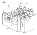
- zeigt eine perspektivische Darstellung einer Bestückvorrichtung mit einem schematisch dargestellten Bestückkopf, welcher Bestückkopf einen kollektiven Drehabtrieb und einen selektiv zustellbaren Hubantrieb für zwei Bauelement-Halteeinrichtungen aufweist.
- Figur 2
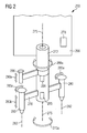
- zeigt eine perspektivische schematische Darstellung eines Zweifach-Bestückkopfes mit einem kollektiven Drehabtrieb und einem selektiv zustellbaren Hubantrieb.
- Figur 3
- zeigt eine Konstruktionszeichnung für einen Mehrfach-Bestückkopf mit einem kollektiven Drehabtrieb und einem selektiv zustellbaren Hubantrieb.
- FIG. 1
- shows a perspective view of a placement device with a schematically shown placement, which placement has a collective rotary drive and a selectively deliverable lifting drive for two component-holding devices.
- FIG. 2
- shows a perspective schematic representation of a dual placement head with a collective rotary drive and a selectively deliverable lifting drive.
- FIG. 3
- shows a construction drawing for a multi-placement head with a collective Drehabtrieb and a selectively deliverable lifting drive.
An dieser Stelle bleibt anzumerken, dass sich in der Zeichnung die Bezugszeichen von gleichen oder von einander entsprechenden Komponenten lediglich in ihrer ersten Ziffer unterscheiden.It should be noted at this point that in the drawing the reference numbers of identical or corresponding components differ only in their first digit.
Die beiden Halteeinrichtungen 180 sind an einem nicht dargestellten Rotor des Mehrfach-Bestückkopfes 150 befestigt, welcher Rotor um eine Rotordrehachse drehbar ist. Die Rotordrehachse ist parallel zu einer zu der x-Richtung und zu der y-Richtung senkrechten z-Richtung orientiert. Die entsprechende Drehbewegung der Halteeinrichtungen 180 bzw. des Rotors ist durch den Doppelpfeil verdeutlicht, der mit dem Bezugszeichen 185a versehen ist.The two
Die Halteeinrichtungen sind sog. Saugpipetten 180, die mittels eines in
Um die Winkellage von aufgenommenen Bauelementen zu korrigieren und um damit die Bauelemente in einer korrekten Orientierung bestücken zu können, ist ferner ein nicht dargestellter Drehaktuator vorgesehen. Mittels des Drehaktuators können beide Saugpipetten 180 in synchroner Weise um ihre jeweilige Längsachse gedreht werden.In order to correct the angular position of recorded components and to be able to equip the components in a correct orientation, an unillustrated rotary actuator is also provided. By means of the rotary actuator, both
Es wird an dieser Stelle ausdrücklich darauf hingewiesen, dass die hier und nachfolgend beschriebene Kombination von einem kollektiven Drehaktuator und einem individuell bereitstellbaren Hubaktuator nicht auf einen Bestückkopf mit lediglich zwei Bauelement-Halteeinrichtungen 180 beschränkt ist.It is expressly pointed out at this point that the combination of a collective rotary actuator and an individually provided lifting actuator described here and below is not restricted to a placement head with only two
Im Prinzip kann der Mehrfach-Bestückkopf beliebig viele Halteeinrichtungen aufweisen, so dass eine entsprechend hohe Anzahl an Bauelementen gleichzeitig transportiert werden kann.In principle, the multiple placement head can have any number of holding devices, so that a correspondingly high number of components can be transported simultaneously.
Die Bestückvorrichtung 100 weist ferner eine Bauelement-Zuführeinrichtung auf, die zumindest zwei Zuführvorrichtungen 110 umfasst, welche an mehreren Abholpositionen 112 der Bestückvorrichtung 100 nicht dargestellte elektronische Bauelemente für den Bestückprozess sequentiell bereitstellen. Dabei können an unterschiedlichen Zuführspuren 110 gleichartige oder auch Bauelemente von unterschiedlichem Typ zugeführt werden.The
Ferner umfasst die dargestellte Bestückvorrichtung 100 ein Förderband 131, mit dem ein Bauelementeträger bzw. ein Substrat 130 in den Bestückbereich eingebracht werden kann. Die Halteeinrichtungen 180 können durch eine entsprechende translatorische und rotatorische Bewegung des Bestückkopfes 150 parallel zu der x-y-Ebene innerhalb des gesamten Bestückbereichs positioniert werden.Furthermore, the
Die Bestückvorrichtung 100 weist außerdem einen Prozessor bzw. eine Datenverarbeitungseinrichtung 101 auf. Auf der Datenverarbeitungseinrichtung 101 kann ein Bearbeitungsprogramm für die Bestückvorrichtung 100 zum Bestücken von Substraten bzw. Leiterplatten mit Bauelementen ausgeführt werden, so dass alle Komponenten der Bestückvorrichtung 100 in synchronisierter Weise arbeiten und somit zu einem fehlerfreien und zügigem Bestücken von Substraten mit Bauelementen beitragen.The
An dem Trägerelement 106 ist zusätzlich eine sog. Leiterplatten-Kamera 140 befestigt, welche zur Erfassung einer an dem Bauelementeträger 130 angebrachten Markierung 132 vorgesehen ist. Auf diese Weise kann die genaue Position des in den Bestückbereich eingebrachten Bauelementeträgers 130 durch eine Lagevermessung der Markierung 132 innerhalb des Gesichtsfeldes der Leiterplatten-Kamera 140 bestimmt werden.A so-called printed
Zur Positionsvermessung und zur Kontrolle von durch den Mehrfach-Bestückkopf 150 aufgenommenen Bauelementen ist eine Kamera 142 vorgesehen, welche gemäß dem hier dargestellten Ausführungsbeispiel in einer festen Position an der Bestückvorrichtung 100 angeordnet ist. Die optische Bauelement-Vermessung erfolgt bevorzugt unmittelbar nach der Aufnahme des Bauelementes bzw. der Bauelemente von der Bauelement-Zuführeinrichtung. Dafür wird der Bestückkopf 150 bzw. die jeweilige Bauelement-Halteeinrichtung 180 in das Gesichtsfeld der Bauelemente-Kamera 142 positioniert. Das von der Kamera 142 aufgenommene Bild wird in einer Auswerteeinheit 145 ausgewertet und dabei die Lage des aufgenommenen Bauelements relativ zu der jeweiligen Saugpipette 180 ermittelt.For position measurement and for the control of components picked up by the
Die Auswerteeinheit 145 kann auch in der Datenverarbeitungseinrichtung 101 integriert sein. Dabei kann die Auswerteeinheit 145 mittels einer eigenen Hardware oder auch mittels einer geeigneten Software realisiert sein.The
Es wird darauf hingewiesen, dass die Erfindung keineswegs auf die Verwendung in der hier dargestellten Bestückvorrichtung 100 beschränkt ist. Die Erfindung kann beispielsweise auch mit einer Bauelemente-Kamera realisiert werden, welche zusammen mit dem Bestückkopf verfahren wird und welche dafür vorgesehen ist, die aufgenommenen Bauelemente während des Transports von der Aufnahmeposition hin zu der Bestückposition zu vermessen.It should be noted that the invention is by no means limited to use in the
Der Rotor 270 ist über eine Hohlwelle 272 mit dem Stator 260 drehbar verbunden, so dass der Rotor 270 um eine Rotordrehachse 275 drehbar ist. Die entsprechende Drehbewegung, welche durch einen Doppelpfeil 275a angedeutet ist, wird von einem schematisch dargestellten Antrieb 278 erzeugt.The
Die Hohlwelle dient der pneumatischen Kopplung der als Saugpipetten ausgebildeten Bauelement-Halteeinrichtungen 280 mit einer nicht dargestellten Vakuum-Erzeugungseinheit. Durch eine entsprechende Beaufschlagung der nicht dargestellten Saugkanäle der Saugpipetten 280 mit Unterdruck kann eine pneumatische Haltekraft auf aufgenommene Bauelemente ausgeübt werden. Beim Absetzen der Bauelemente wird dieser Unterdruck selektiv abgeschaltet. Das Ablösen des Bauelements kann in bekannter Weise durch eine kurzfristige Umschaltung eines Pneumatikventils unterstützt werden. Dabei wird der Saugkanal kurzzeitig mit einem leichten Überdruck beaufschlagt, so dass an der Oberfläche eines aufgenommenen Bauelements kurzzeitig eine leichter Überdruck anliegt, der ein Ablösen des Bauelements von der Saugpipette unterstützt.The hollow shaft serves for the pneumatic coupling of the
An dem Rotor 270 sind außerhalb der Rotordrehachse 275 die beiden Halteeinrichtungen 280 angeordnet, so dass sie sich bei einer Drehung des Rotors 270 ebenfalls um die Rotordrehachse 275 drehen. Die Halteeinrichtungen sind außerdem jeweils um ihre Längsachse 282 drehbar gelagert.On the
Sämtliche Halteeinrichtungen 280 sind außerdem mit einem gemeinsamen Drehaktuator 285 in nicht näher dargestellter Weise beispielsweise mittel eines Riemens gekoppelt. Bei einer Aktivierung des kollektiven Drehantriebs 285 werden somit alle Haltevorrichtungen in synchroner Weise um ihre jeweilige Drehachse 282 gedreht. Diese Eigenrotation der Haltevorrichtungen ist durch die beiden Doppelpfeile 285a angedeutet.All holding
Der Bestückkopf weist ferner einen ebenfalls um die Rotordrehachse 275 drehbar gelagerten Hubaktuator 290 auf. Die Drehung des Hubaktuators 290, welche durch den Doppelpfeil 288a angedeutet ist, kann vollständig unabhängig sowohl von der Drehung des Rotors 270 als auch unabhängig von der Eigenrotation der Halteeinrichtungen 280 erfolgen. Die relative Winkellage zwischen dem Hubaktuator 290 und dem Rotor 270 bzw. den Haltevorrichtungen 280 wird durch eine entsprechende Aktivierung eines Drehantriebs 288 eingestellt. Damit kann der Hubaktuator 290 selektiv mit einer der zumindest zwei Haltevorrichtungen 280 gekoppelt werden. Bei einer entsprechenden Aktivierung des Hubaktuators 290, welche durch einen Doppelpfeil 290a veranschaulicht ist, kann dann die jeweilige Bauelement-Haltevorrichtung 280 relativ zu dem Chassis 260 angehoben bzw. abgesenkt werden. Die durch den Hubaktuator 290 erzeugte Hubbewegung der Bauelement-Haltevorrichtung 280 ist in
An dem Rotor 370 sind außerhalb der Drehachse 375 zumindest zwei Bauelement-Halteeinrichtungen 380 angeordnet, die zum temporären Aufnehmen von elektronischen Bauelementen eingerichtet sind. Die Haltevorrichtungen 380 sind entlang einer z-Achse verschiebbar gelagert und werden von jeweils einem Federelement 381 in eine obere Ausgangslage gedrückt.Arranged on the
Die Haltevorrichtungen 380 sind ferner jeweils um ihre Längsachse 382 drehbar gelagert und mittels eines zentralen Drehaktuators kollektiv d.h. gemeinsam antreibbar. Der schematisch dargestellte zentrale Drehaktuator ist mit dem Bezugszeichen 385 versehen. Bei einer Aktivierung des zentralen Drehaktuators 385 werden alle Haltevorrichtungen 380 gemeinsam zu einer Rotation um ihre jeweilige Längsachse 382 veranlasst.The holding
Gemäß dem hier dargestellten Ausführungsbeispiel der Erfindung sind die Haltevorrichtungen 380 über eine zweite Hohlwelle 389 und Koppelelemente 386 mit dem Drehaktuator 386 gekoppelt. Die Koppelelemente 386 können beispielsweise Zahnräder, Reibräder oder Riemen sein. Die zweite Hohlwelle 389 ist auf der ersten Hohlwelle 372 aufgesteckt. Lagerungen 389a ermöglichen eine reibungsarme relative Drehung zwischen der zweiten Hohlwelle 389 und der ersten Hohlwelle 372.According to the exemplary embodiment of the invention illustrated here, the holding
Der Bestückkopf 350 weist ferner einen in Bezug auf den Rotor 370 drehbar gelagerten Hubaktuator 390 auf, der in
Gemäß dem hier dargestellten Ausführungsbeispiel ist der Hubaktuator 390 an einer dritten Hohlwelle 396 befestigt. Die dritte Hohlwelle 396 ist konzentrisch zu den beiden anderen Hohlwellen 372 und 389 angeordnet und mittels Lagerungen 396a relativ zu der Rotordrehachse 375 zentriert. Die Lagerungen 396a erlauben eine reibungsarme Drehlagerung der dritten Hohlwelle 396 relativ zu der zweiten Hohlwelle 372, auf welcher die dritte Hohlwelle 396 aufgesteckt ist.According to the embodiment shown here, the
Eine Kopplung zwischen Hubaktuator 390 und einer der Bauelement-Halteeinrichtungen 380 wird dadurch erreicht, dass der Hubaktuator 390 zunächst in eine in Bezug auf den Rotor 370 geeignete Winkellage gebracht wird, so dass ein Koppelelement 392 des Hubaktuators 390 in ein Mitnehmerelement 395 eingreift, welches der gewünschten Halteeinrichtung 380 zugeordnet ist. Das Mitnehmerelement 395 ist an einem Stößel 397 angebracht, welcher mittels eines Linearlagers 398 entlang der z-Achse verschiebbar ist. Bei einer Abwärtsbewegung des Hubaktuators 390 drückt somit der Stößel 397 auf das zuvor beschriebene Koppelelement 386, so dass die entsprechende Bauelement-Halteeinrichtung 380 unter Überwindung der Spannkraft des Federelements 381 nach unten gedrückt wird. Bei einer Aufwärtsbewegung des Hubaktuators 390 wird die Halteeinrichtung 380 infolge der Spannkraft des Federelements 381 wieder in ihre Ausgangslage zurück gebracht. Auf diese Weise kann unabhängig von der Winkellage des Rotors 370 jede beliebige Bauelement-Halteeinrichtung in Bezug auf das Chassis des Bestückkopfes individuell entlang der z-Richtung verschoben werden. Damit wird die Flexibilität des Bestückkopfes 350 bezüglich möglicher Sequenzen von Aufnahme- und Absetzvorgängen von unterschiedlichen Bauelementen im Rahmen der automatischen Bestückung von Substraten mit elektronischen Bauelementen im Vergleich zu bekannten Bestückköpfen mit einem stationären Hubaktuator erheblich erhöht.A coupling between
Es wird darauf hingewiesen, dass die hier beschriebenen Ausführungsformen lediglich eine beschränkte Auswahl an möglichen Ausführungsvarianten der Erfindung darstellen. So ist es möglich, die Merkmale einzelner Ausführungsformen in geeigneter Weise miteinander zu kombinieren, so dass für den Fachmann mit den hier expliziten Ausführungsvarianten eine Vielzahl von verschiedenen Ausführungsformen als offensichtlich offenbart anzusehen sind.It should be noted that the embodiments described herein represent only a limited selection of possible embodiments of the invention. Thus, it is possible to combine the features of individual embodiments in a suitable manner with one another, so that for the person skilled in the art with the variants of embodiment which are explicit here, a Variety of different embodiments are to be regarded as obviously disclosed.
Diese Anmeldung beschreibt einen Bestückkopf 250 zum Bestücken von Substraten mit Bauelementen. Der Bestückkopf 250 umfasst (a) einen Stator 260, (b) einen Rotor 270, welcher relativ zu dem Stator 260 um eine Rotordrehachse 275 drehbar ist, und (c) zumindest zwei Bauelement-Halteeinrichtungen 280, welche am Rotor 270 in einer zu der Rotordrehachse 275 senkrecht orientierten Ebene angeordnet sind. Die Halteeinrichtungen 280 sind relativ zu dem Rotor 270 um jeweils eine zur Rotordrehachse 275 parallele Drehachse 282 drehbar und in einer zu der Drehachse 282 parallelen Verschieberichtung 285b verschiebbar gelagert. Der Bestückkopf 250 umfasst ferner (d) einen Drehaktuator 285, welcher mit den Halteeinrichtungen 280 derart gekoppelt ist, dass diese bei einer Aktivierung des Drehaktuators 285 jeweils um ihre Drehachsen 282 gedreht werden, und (e) einen Hubaktuator 290, welcher relativ zu dem Rotor 270 um die Rotordrehachse 275 drehbar gelagert und durch Drehung einer ausgewählten Halteeinrichtung 280 individuell zustellbar ist und welcher derart ausgebildet ist, dass er mit der ausgewählten Halteeinrichtung 280 individuell koppelbar ist und eine Hubbewegung der ausgewählten Halteeinrichtung 280 in der Verschieberichtung 285b bewirken kann.This application describes a
- 100100
- BestückvorrichtungMounting device
- 101101
- Datenverarbeitungseinrichtung / ProzessorData processing device / processor
- 102102
- Rahmenframe
- 103103
- Führungenguides
- 104104
- querstehender Trägerarmtransverse support arm
- 105105
- Führungguide
- 106106
- Trägerelementsupport element
- 110110
- Zuführvorrichtungenfeeders
- 112112
- Abholpositionenpick-up locations
- 130130
- Bauelementeträger / SubstratComponent carrier / substrate
- 131131
- Förderbandconveyor belt
- 132132
- Markierungmark
- 140140
- Leiterplatten-KameraPCB camera
- 142142
- Bauelemente-KameraComponents Camera
- 145145
- Auswerteeinheitevaluation
- 150150
- Bestückkopfplacement
- 180180
- Halteeinrichtung / SaugpipetteHolding device / suction pipette
- 185a185a
- Drehrichtung RotorDirection of rotation rotor
- 250250
- Bestückkopfplacement
- 260260
- Chassis / StatorChassis / stator
- 270270
- Rotorrotor
- 272272
- erste Hohlwellefirst hollow shaft
- 275275
- RotordrehachseRotor axis of rotation
- 275a275a
-
Drehrichtung Rotor 270Direction of
rotation rotor 270 - 278278
-
Antrieb für Rotor 270Drive for
rotor 270 - 280280
- Halteeinrichtungenholding devices
- 282282
- Drehachse / LängsachseRotation axis / longitudinal axis
- 285285
- Drehaktuator / kollektiver DrehantriebRotary actuator / collective rotary drive
- 285a285a
- kollektive Drehrichtung der Halteeinrichtungencollective direction of rotation of the holding devices
- 285b285b
- individuelle Verschieberichtung einer Halteeinrichtungindividual displacement direction of a holding device
- 288288
- Drehantrieb für HubaktuatorRotary actuator for lifting actuator
- 288a288a
- Drehrichtung HubaktuatorDirection of rotation lift actuator
- 290290
- drehbarer Hubaktuatorrotatable lifting actuator
- 290a290a
- Verschieberichtung HubaktuatorDisplacement direction Hubaktuator
- 350350
- Bestückkopfplacement
- 360360
- Chassis / StatorChassis / stator
- 370370
- Rotorrotor
- 372372
- erste Hohlwelle (für Rotor 370)first hollow shaft (for rotor 370)
- 372a372a
- Lagerungenoverlays
- 375375
- RotordrehachseRotor axis of rotation
- 378378
-
Antrieb für Rotor 370Drive for
rotor 370 - 380380
- Halteeinrichtungholder
- 381381
- Federelementspring element
- 382382
- Drehachse / LängsachseRotation axis / longitudinal axis
- 385385
- Drehaktuator / kollektiver DrehantriebRotary actuator / collective rotary drive
- 386386
- Koppelelementecoupling elements
- 388388
- Drehantrieb für HubaktuatorRotary actuator for lifting actuator
- 389389
- zweite Hohlwelle (für kollektiven Drehantrieb)second hollow shaft (for collective rotary drive)
- 389a389a
- Lagerungenoverlays
- 390390
- drehbarer Hubaktuatorrotatable lifting actuator
- 391391
- Antrieb mit Spindel und RiemenDrive with spindle and belt
- 392392
- Koppelelementcoupling element
- 395395
- Mitnehmerelementdogging
- 396396
- dritte Hohlwelle (für Drehung Hubaktuator)third hollow shaft (for rotation stroke actuator)
- 396a396a
- Lagerungenoverlays
- 397397
- Stößeltappet
- 398398
- Linearlagerlinear bearings
Claims (10)
- A mounting head for mounting electronic components on substrates (130), said mounting head (150, 250, 350) comprising• a stator (260, 360),• a rotor (270, 370), which can be rotated relative to the stator (260, 360) about a rotor rotation axis (275, 375),• at least two retaining devices (280, 380) for temporarily picking up the electronic components, which retaining devices (280, 380) are arranged on the rotor (270, 370) in a plane oriented perpendicular to the rotor rotation axis (275, 375), wherein• the retaining devices (280, 380) are pivotably mounted relative to the rotor (270, 370) each about an axis of rotation (282, 282) parallel to the rotor rotation axis (275, 375), and are mounted such that they can be displaced in a displacement direction (285b) parallel to the axis of rotation (282, 382),• a rotary actuator (285, 385), which is coupled to the retaining devices (280, 380) in such a manner that when the rotary actuator (285, 385) is activated the retaining devices (280, 380), independent of the actual angle of rotation of the rotor (270, 370), are rotated about their rotary axes (282, 382), and• a lifting actuator (290, 390), whichis designed in such a manner that it can be individually coupled to the one retaining device (280, 380) and can effect a lifting movement (285b) of the one retaining device (280) in the displacement direction.- is mounted relative to the rotor (270, 370) and to the stator (260, 360) such that it can pivot about the rotor rotation axis (275, 375),- one retaining device (280, 380) of the at least two retaining devices (280, 380) is individually adjustable by rotation and
- The mounting head according to claim 1,
additionally comprising a further lifting actuator, which is designed in such a manner that it can be coupled with a further retaining device and can effect a lifting movement of the further retaining device in the displacement direction. - The mounting head according to claim 2, wherein
the further lifting actuator is arranged relative to the stator (260, 360) in a fixed angular position in relation to the stator (260, 360) and/or in relation to the rotor (270, 370). - The mounting head according to claim 2, wherein
the further lifting actuator is mounted such that it can pivot relative to the rotor (270, 370) and the stator (260, 360) about the rotor rotation axis (275, 375) and is individually adjustable by rotation relative to the stator (260, 360) of a further retaining device of the at least two retaining devices (280, 380), and wherein
the further lifting actuator is designed in such a manner that it can be individually coupled to the one further retaining device and can effect a lifting movement of the one further retaining device in the displacement direction. - The mounting head according to any one of claims 1 to 4, wherein
the lifting actuator and/or the further lifting actuator comprise a coupling element (393), which can be brought into engagement with a driver element (395), the driver element (395) being assigned to one of the at least two retaining devices (380). - The mounting head according to any one of claims 1 to 5, additionally comprising
at least two spring elements (381), which are arranged in such a manner that they each push one retaining device (380) of the at least two retaining devices (380) into a starting position, wherein, when the lifting actuator (390) or the further lifting actuator is activated, the retaining device (380) can be deflected along the displacement direction parallel to the axis of rotation (382). - The mounting head according to any one of claims 1 to 6, wherein
the rotary actuator (285, 385), the lifting actuator (290, 390), a rotary drive (388) for the lifting actuator (390) and/or a rotary drive (378) for the rotor (370) are arranged outside of the rotor rotation axis (375). - The mounting head according to any one of claims 1 to 7, additionally comprising• at least two further retaining devices for temporarily picking up the electronic components, which retaining devices are arranged on the rotor (270, 370) in a plane oriented perpendicular to the rotor rotation axis (275, 375), whereinwherein the rotary actuator (285, 385) is also coupled to the further retaining devices in such a manner that when the rotary actuator (285, 385) is activated, the further retaining devices are each rotated about their respective rotary axes, and wherein also the lifting actuator (290, 390) of a further retaining device of the at least two further retaining devices is individually adjustable, can be individually coupled to a further retaining device and can effect a lifting movement of the one further retaining device in the displacement direction.
the further retaining devices are pivotably mounted relative to the rotor (270, 370) about an axis of rotation parallel to the rotor rotation axis (275, 375), and are mounted such that they can be displaced in a displacement direction parallel to the axis of rotation, - A mounting device for mounting electronic components on substrates (130), said mounting device (100) comprising• a mounting head (150, 250, 350) according to any one of claims 1 to 8.
- A method for mounting electronic components on substrates (130), said method comprising• picking up of at least two components of a component feeding device (110) using a mounting head (150, 250, 350) according to any one of claims 1 to 8,• positioning of the mounting head (150, 250, 350) relative to a substrate (130) to be assembled, and• placement of the components on the substrate (130) at pre-specified placement positions defined by component contact pads.
Applications Claiming Priority (1)
| Application Number | Priority Date | Filing Date | Title |
|---|---|---|---|
| DE102007005151A DE102007005151A1 (en) | 2007-02-01 | 2007-02-01 | Multiple placement head with collective rotary drive and movable lifting drive for component holding devices |
Publications (3)
| Publication Number | Publication Date |
|---|---|
| EP1954115A2 EP1954115A2 (en) | 2008-08-06 |
| EP1954115A3 EP1954115A3 (en) | 2010-12-15 |
| EP1954115B1 true EP1954115B1 (en) | 2014-07-16 |
Family
ID=39338518
Family Applications (1)
| Application Number | Title | Priority Date | Filing Date |
|---|---|---|---|
| EP08100520.9A Active EP1954115B1 (en) | 2007-02-01 | 2008-01-16 | Multiple mounting head with collective rotary drive and adjustable lifting device for component holding devices |
Country Status (4)
| Country | Link |
|---|---|
| EP (1) | EP1954115B1 (en) |
| JP (1) | JP2008193075A (en) |
| CN (1) | CN101272678B (en) |
| DE (1) | DE102007005151A1 (en) |
Families Citing this family (2)
| Publication number | Priority date | Publication date | Assignee | Title |
|---|---|---|---|---|
| MY184276A (en) * | 2015-02-16 | 2021-03-30 | Exis Tech Sdn Bhd | Device and method for conveying and flipping a component |
| CN112379202B (en) * | 2020-11-13 | 2022-04-12 | 广东电网有限责任公司 | Test device for gas-insulated transformer |
Family Cites Families (5)
| Publication number | Priority date | Publication date | Assignee | Title |
|---|---|---|---|---|
| JPH11289194A (en) * | 1998-04-06 | 1999-10-19 | Matsushita Electric Ind Co Ltd | Apparatus and method for mounting electronic component |
| JP2001345596A (en) * | 2000-06-01 | 2001-12-14 | Fuji Mach Mfg Co Ltd | Electrical component attaching apparatus |
| JP4408682B2 (en) * | 2003-10-31 | 2010-02-03 | 株式会社日立ハイテクインスツルメンツ | Electronic component mounting device |
| JP2005228992A (en) * | 2004-02-13 | 2005-08-25 | Hitachi High-Tech Instruments Co Ltd | Electronic component mounting apparatus |
| JP4559243B2 (en) * | 2005-01-28 | 2010-10-06 | 株式会社日立ハイテクインスツルメンツ | Electronic component mounting method and electronic component mounting apparatus |
-
2007
- 2007-02-01 DE DE102007005151A patent/DE102007005151A1/en not_active Withdrawn
-
2008
- 2008-01-16 EP EP08100520.9A patent/EP1954115B1/en active Active
- 2008-01-24 JP JP2008013919A patent/JP2008193075A/en active Pending
- 2008-01-31 CN CN2008100052496A patent/CN101272678B/en active Active
Also Published As
| Publication number | Publication date |
|---|---|
| DE102007005151A1 (en) | 2008-08-07 |
| EP1954115A2 (en) | 2008-08-06 |
| CN101272678A (en) | 2008-09-24 |
| CN101272678B (en) | 2011-09-21 |
| JP2008193075A (en) | 2008-08-21 |
| EP1954115A3 (en) | 2010-12-15 |
Similar Documents
| Publication | Publication Date | Title |
|---|---|---|
| EP0807258B1 (en) | Test device for flat electronic assemblies | |
| EP0984675B1 (en) | Apparatus for aligning a support for electronic circuits | |
| DE102016117815B4 (en) | Caching of FCOB chips in a chip transfer device | |
| DE2834836A1 (en) | DEVICE FOR APPLYING ELECTRONIC COMPONENTS TO A HYBRID LADDER CARRIER | |
| DE4301585A1 (en) | Mounting device for plugging electronic components into PCB - has mounting stations to position PCB in Y direction and mounting head movable in X direction and component stores at each station | |
| DE102007020779B3 (en) | Automatic placement machine for loading electrical and / or optical components on substrates | |
| DE102007047596A1 (en) | Handling device for electronic components, in particular ICs, with a plurality of guided in an orbit circulation car | |
| EP2111092B1 (en) | Loading head, automatic loader, method for fetching construction elements and method for loading substrates | |
| DE102008010236B4 (en) | Device for transporting substrates in a placement machine, automatic placement machine and method for transporting substrates | |
| DE102014103373B4 (en) | Placement head with two groups of quills that can be moved relative to a shaft, placement machine and process for placement | |
| EP1954115B1 (en) | Multiple mounting head with collective rotary drive and adjustable lifting device for component holding devices | |
| DE102008019101B4 (en) | Method for loading substrates and placement machine | |
| DE102018122593B3 (en) | Placement head with intermeshing rotors, placement machine, method for loading a component carrier | |
| DE102020116385B3 (en) | Placement head with two rotor arrangements with individually actuatable handling devices, placement machine and method for the automatic placement of a component carrier | |
| DE102006045301B4 (en) | Positioning system with magnetically preloaded linear axis | |
| EP1868238A2 (en) | Clamping device for a wafer | |
| EP1862048B1 (en) | Pick-and-place robot for placing electrical components on substrates | |
| DE102005035420B4 (en) | Modular device for loading substrates | |
| DE102008023614B3 (en) | Supporting pin positioning method for use in assembly machine, involves moving displacement device in x-direction and y-direction, such that pin is moved to predefined position on table through displacement movement in x and y-directions | |
| DE102006046028B4 (en) | Displacement device for a component holding device with central force introduction | |
| DE102018102417A1 (en) | Device for transporting and aligning one or more flat components | |
| DE10207422C1 (en) | Working station for assembly machine has linear feed with support for carriage driven by linear motor | |
| DE10235471A1 (en) | Printed circuit board assembly method has position of each component detected via camera for accurate positioning relative to printed circuit board | |
| DE10212935A1 (en) | Equipping head for mounting electrical components on substrates, has movable adjustment pieces on ends of leaf spring to vary spacing between ends |
Legal Events
| Date | Code | Title | Description |
|---|---|---|---|
| PUAI | Public reference made under article 153(3) epc to a published international application that has entered the european phase |
Free format text: ORIGINAL CODE: 0009012 |
|
| AK | Designated contracting states |
Kind code of ref document: A2 Designated state(s): AT BE BG CH CY CZ DE DK EE ES FI FR GB GR HR HU IE IS IT LI LT LU LV MC MT NL NO PL PT RO SE SI SK TR |
|
| AX | Request for extension of the european patent |
Extension state: AL BA MK RS |
|
| RAP1 | Party data changed (applicant data changed or rights of an application transferred) |
Owner name: SIEMENS ELECTRONICS ASSEMBLY SYSTEMS GMBH & CO. KG |
|
| PUAL | Search report despatched |
Free format text: ORIGINAL CODE: 0009013 |
|
| AK | Designated contracting states |
Kind code of ref document: A3 Designated state(s): AT BE BG CH CY CZ DE DK EE ES FI FR GB GR HR HU IE IS IT LI LT LU LV MC MT NL NO PL PT RO SE SI SK TR |
|
| AX | Request for extension of the european patent |
Extension state: AL BA MK RS |
|
| RAP1 | Party data changed (applicant data changed or rights of an application transferred) |
Owner name: ASM ASSEMBLY SYSTEMS GMBH & CO. KG |
|
| 17P | Request for examination filed |
Effective date: 20110615 |
|
| AKX | Designation fees paid |
Designated state(s): DE |
|
| 17Q | First examination report despatched |
Effective date: 20131203 |
|
| GRAP | Despatch of communication of intention to grant a patent |
Free format text: ORIGINAL CODE: EPIDOSNIGR1 |
|
| INTG | Intention to grant announced |
Effective date: 20140225 |
|
| GRAS | Grant fee paid |
Free format text: ORIGINAL CODE: EPIDOSNIGR3 |
|
| GRAA | (expected) grant |
Free format text: ORIGINAL CODE: 0009210 |
|
| AK | Designated contracting states |
Kind code of ref document: B1 Designated state(s): DE |
|
| REG | Reference to a national code |
Ref country code: DE Ref legal event code: R096 Ref document number: 502008012003 Country of ref document: DE Effective date: 20140904 |
|
| REG | Reference to a national code |
Ref country code: DE Ref legal event code: R097 Ref document number: 502008012003 Country of ref document: DE |
|
| PLBE | No opposition filed within time limit |
Free format text: ORIGINAL CODE: 0009261 |
|
| STAA | Information on the status of an ep patent application or granted ep patent |
Free format text: STATUS: NO OPPOSITION FILED WITHIN TIME LIMIT |
|
| 26N | No opposition filed |
Effective date: 20150417 |
|
| REG | Reference to a national code |
Ref country code: DE Ref legal event code: R081 Ref document number: 502008012003 Country of ref document: DE Owner name: ASMPT GMBH & CO. KG, DE Free format text: FORMER OWNER: ASM ASSEMBLY SYSTEMS GMBH & CO. KG, 81379 MUENCHEN, DE |
|
| PGFP | Annual fee paid to national office [announced via postgrant information from national office to epo] |
Ref country code: DE Payment date: 20230123 Year of fee payment: 16 |
|
| P01 | Opt-out of the competence of the unified patent court (upc) registered |
Effective date: 20230530 |