EP0806715B1 - Verfahren zum Regeln eines rechnergesteuerten Regalbediengerätes - Google Patents
Verfahren zum Regeln eines rechnergesteuerten Regalbediengerätes Download PDFInfo
- Publication number
- EP0806715B1 EP0806715B1 EP95118823A EP95118823A EP0806715B1 EP 0806715 B1 EP0806715 B1 EP 0806715B1 EP 95118823 A EP95118823 A EP 95118823A EP 95118823 A EP95118823 A EP 95118823A EP 0806715 B1 EP0806715 B1 EP 0806715B1
- Authority
- EP
- European Patent Office
- Prior art keywords
- shelf
- drive
- regulating
- servicing apparatus
- dynamic
- Prior art date
- Legal status (The legal status is an assumption and is not a legal conclusion. Google has not performed a legal analysis and makes no representation as to the accuracy of the status listed.)
- Expired - Lifetime
Links
Images
Classifications
-
- G—PHYSICS
- G05—CONTROLLING; REGULATING
- G05B—CONTROL OR REGULATING SYSTEMS IN GENERAL; FUNCTIONAL ELEMENTS OF SUCH SYSTEMS; MONITORING OR TESTING ARRANGEMENTS FOR SUCH SYSTEMS OR ELEMENTS
- G05B19/00—Program-control systems
- G05B19/02—Program-control systems electric
- G05B19/18—Numerical control [NC], i.e. automatically operating machines, in particular machine tools, e.g. in a manufacturing environment, so as to execute positioning, movement or co-ordinated operations by means of program data in numerical form
- G05B19/19—Numerical control [NC], i.e. automatically operating machines, in particular machine tools, e.g. in a manufacturing environment, so as to execute positioning, movement or co-ordinated operations by means of program data in numerical form characterised by positioning or contouring control systems, e.g. to control position from one programmed point to another or to control movement along a programmed continuous path
-
- B—PERFORMING OPERATIONS; TRANSPORTING
- B66—HOISTING; LIFTING; HAULING
- B66F—HOISTING, LIFTING, HAULING OR PUSHING, NOT OTHERWISE PROVIDED FOR, e.g. DEVICES WHICH APPLY A LIFTING OR PUSHING FORCE DIRECTLY TO THE SURFACE OF A LOAD
- B66F9/00—Devices for lifting or lowering bulky or heavy goods for loading or unloading purposes
- B66F9/06—Devices for lifting or lowering bulky or heavy goods for loading or unloading purposes movable, with their loads, on wheels or the like, e.g. fork-lift trucks
- B66F9/07—Floor-to-roof stacking devices, e.g. "stacker cranes", "retrievers"
-
- Y—GENERAL TAGGING OF NEW TECHNOLOGICAL DEVELOPMENTS; GENERAL TAGGING OF CROSS-SECTIONAL TECHNOLOGIES SPANNING OVER SEVERAL SECTIONS OF THE IPC; TECHNICAL SUBJECTS COVERED BY FORMER USPC CROSS-REFERENCE ART COLLECTIONS [XRACs] AND DIGESTS
- Y10—TECHNICAL SUBJECTS COVERED BY FORMER USPC
- Y10S—TECHNICAL SUBJECTS COVERED BY FORMER USPC CROSS-REFERENCE ART COLLECTIONS [XRACs] AND DIGESTS
- Y10S706/00—Data processing: artificial intelligence
- Y10S706/902—Application using ai with detail of the ai system
- Y10S706/903—Control
- Y10S706/905—Vehicle or aerospace
Definitions
- the invention relates to a method for regulating the drive a computer-controlled one, and a mast on a moving frame with an attached to it, with a load handler provided lifting platform comprising storage and retrieval device, comprising a current control circuit, including a speed control circuit Drive control loop and a position control loop.
- a control method has become known from US Pat. No. 5,239,248. that the control loops mentioned and also a status and Has observer.
- the manipulated variables are calculated on the basis of signals obtained by means of the observer in one central unit. Apart from the fact that there is only one can process a limited number of measured and manipulated variables, this known method is also involved exclusively for position control.
- the mentioned storage and retrieval machines such as become known, for example, from DE-C 38 03 626 for example in logistic systems that are considered essential Component include a high-bay warehouse, in fully automatic or manual operation the transport task, i.e. the Transfer of a loading unit from the storage location to the storage location and from there to the swap site.
- the range of goods to be stored Goods extends from the small container weighing only a few kilograms up to approx. 40 tons heavy coils, for example, metal strips wound into bundles.
- the warehouse heights and depending on the height of the storage and retrieval machines move in a range from approx. 6 m to 45 m.
- the respective Bearing dimensions are based on the freely movable or on Rail guided storage and retrieval machine by its drive in the horizontal X direction, by the linear actuator of the the vertical mast vertically movable lifting drive for the lifting platform in the vertical Y direction and through the Load handler drive developed in Z direction.
- the high, slim masts, on which the ones already mentioned are sometimes right large loads are moved up and down, are flexible, extreme vibratory systems with variable dynamic Properties that e.g. through motor acceleration and Deceleration, road bumps, brake application and controller influence can be stimulated.
- the interfaces mentioned limit the controller hierarchically downwards; the interface up is through the Storage and retrieval machine control specified that the controller Communicates target points of the driving movements and for Safety functions, limit switches, coordination tasks, Fault diagnosis, communication with the warehouse management computer, etc. responsible is.
- Position measuring systems are in a form-fitting, slip-free version and in a frictionally locking version with subsequent fine positioning usual.
- Regulator concepts that belong to the state of the art are the so-called “3-point position controller” and the “cascade controller", the outgoing of three different, cascaded Controller circuits are formed: The current control loop as an inner Loop, the speed control loop and the position control loop as the outer Circle.
- the "3-point position controller” strictly speaking, not a position controller, but a path-dependent one Speed control, with the result that a multi-stage, Delay process involving loss of time arises. There no continuous comparison between actual position and setpoint takes place, the cumulative position differences can only be at the end of the deceleration process during a creep speed compensate at reduced speed.
- the invention is therefore based on the object to create a generic control method that enables that are limited in the known controller concepts Intervention options and narrow technical limits are crucial to expand.
- This object is achieved in that the momentary dynamic behavior of the storage and retrieval machine existing data of a state and Fault monitoring module, using information about the device dynamics containing measured and control variables and on the basis of coefficient maps, where the Characteristic maps of constructive details or dynamic Include the properties of the conveyor and start from a basic setting of device-dynamic variables of the Storage and retrieval machine and an iterative estimation algorithm from one an automatic self-learning coefficient identification executing controller module determined and on the basis mathematical equations of the calculated momentary dynamic behavior , when controlling the drive, vibrations of the storage and retrieval machine are actively damped. It lies thus an active, the current dynamic state of the storage and retrieval machine considering vibration damping advanced, self-learning adaptive state controller, which results in a significantly wider range of Optimization opportunities.
- the control procedure integrated in addition to the internal current control loop, the speed control loop and the position control loop further, information about the current dynamic behavior of the storage and retrieval device Information, e.g. mast deflection and relative Speed of the mast tip and the position deviation at positive toothed belt drives.
- the storage and retrieval device Information e.g. mast deflection and relative Speed of the mast tip and the position deviation at positive toothed belt drives.
- the control method according to the invention has no constant Coefficients, but special coefficient maps, the crucial of those in control engineering in general usual, e.g. through the DE-Z "automation technology, vol. 43, No. 8, August 1, 1995, pages 363 to 367 Maps differ, namely construction details or Include dynamic properties of the conveyor. For this count for example the number of existing masts (one or two), the rigidity of the mast, the load position (height the lifting platform or rope length) and the weight of the payload. It So no control parameters are stored, but data from which the control parameters are always calculated.
- the controller module performs an automatic self-learning coefficient identification by by using it from a basic setting the mathematical model of the storage and retrieval machine and one iterative estimation algorithm determines the maps.
- the Learning mode of the controller module takes place in the form that a test drive runs automatically and in the constant speed phase an additional current test signal is applied as a reference variable becomes.
- the estimation algorithm calculates from the target / actual comparison the parameters of the transfer function, which in turn are using of the mathematical model for the coefficient maps to lead. Due to this regulation, ideally, any Avoided swinging.
- a preferred embodiment of the invention provides that a Current wheel pressure of the stacker crane from the status and Fault monitor module calculated and in the drive or Speed control loop the drive torque or the motor current the currently possible or - in the case of metrological recording - that possible maximum is to be expected.
- the active vibration damping realized this Counteracts influence, which enables Torque monitoring based on a corresponding Controller module the elimination of this influence in the Drive control loop.
- Torque monitoring controller module therefore consists in that always according to the dynamic behavior of the Storage and retrieval machine the current maximum of acceleration or Braking torque is transmitted.
- the torque or Motor current regulator loop through a continuous comparison of drive speed and absolute speed of the storage and retrieval machine taking into account the actually traveled by one Absolute distance measuring system overlaps and determined if differences occur, the motor is corrected. At occurring, e.g. differences caused by hatching in this case the controller will correct the Motor current causes.
- this effort is no longer necessary necessary because another controller module with the help of the status and Fault monitoring module taking into account actual load and platform height as well as including of the corresponding deformation map the position error continuously calculated and an automatic correction of the Position setpoint is carried out.
- Energy consumption of the storage and retrieval machine depends on the current one Utilization regulated. Saving energy costs and in the sense of this includes increased environmental awareness control method according to the invention thus a strategy controller module, that allows, according to the current Utilization situation of the stacker crane each select energy-minimal operating strategy or method.
- a strategy controller module that allows, according to the current Utilization situation of the stacker crane each select energy-minimal operating strategy or method.
- At a high required throughput are lifting and Travel drive time-synchronized, i.e. becomes the faster axis by reducing the acceleration or deceleration of the adjusted slower axis.
- Is the one to be provided Throughput performance rather low, is according to the actual throughput and thus the maximum depending on the order Energy consumption in the form of acceleration and Delay limit values specified.
- the invention further provides that the positioning accuracy of the storage and retrieval machine to the different Transport units or stored goods adjusted differently adjusted becomes.
- a positioning controller module into the control method according to the invention can be the respective Positioning tolerance depending on the respective transport unit choose freely. This makes it possible to cover the wide range of goods to be stored in terms of weight, dimensions and To take load carriers into account.
- the different Transport units require for safe transfer from Storage and retrieval machine in the storage compartment of the high-bay warehouse different position tolerances, whereby by Position controller module can achieve that for compliance positioning seasons as short as possible is higher than absolutely necessary.
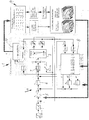
- the controller 1 includes a Reference variable generator 3, a cascade controller 4 with a Position controller 5 and a speed controller 6 and a current controller 7. These are connected to the corresponding control loops with the Storage and retrieval machine 2 as well as a status and Interference observer controller module 8 linked using a mathematical model from existing data for description the device dynamics required additional information calculated. It does not use constant coefficients, but assumed coefficient maps that from a automatic self-learning coefficient identification implementing controller module 9 on the basis of a Basic setting of the sizes of the storage and retrieval machine 2 and one Module 10 are determined for an iterative estimation algorithm.
- the controller 1 combines active vibration damping as advantages to eliminate vibrations and reduce the cooldown, the fastest possible approximation due to the position control the target point, an optimal controller penetration and one lower drag error, anti-slip control and there there is no vibration excitation - higher Acceleration values.
- the control parameters can be taking into account different loads, lifting heights and geometries, a different design dynamic behavior, different drives and type of Power transmission and different static and dynamic Optimize deformations.
- freely selectable, if applicable, combinable operating strategies become.
Landscapes
- Engineering & Computer Science (AREA)
- Transportation (AREA)
- Structural Engineering (AREA)
- Civil Engineering (AREA)
- Life Sciences & Earth Sciences (AREA)
- Geology (AREA)
- Mechanical Engineering (AREA)
- Manufacturing & Machinery (AREA)
- Human Computer Interaction (AREA)
- Physics & Mathematics (AREA)
- General Physics & Mathematics (AREA)
- Automation & Control Theory (AREA)
- Warehouses Or Storage Devices (AREA)
- Control Of Position Or Direction (AREA)
- Control And Safety Of Cranes (AREA)
- Feedback Control In General (AREA)
- Control Of Conveyors (AREA)
Description
Claims (6)
- Verfahren zum Regeln des Antriebs eines rechnergesteuerten, auf einem Fahrrahmen einen Mast mit einer daran angeordneten, mit einem Lastaufnahmemittel versehenen Hubbühne aufweisenden Regalbediengerätes (2), umfassend einen Stromregelkreis (7), einen einen Drehzahlregelkreis (6) einschließenden Antriebsregelkreis und einen Lageregelkreis (5),
dadurch gekennzeichnet,
daß das momentane dynamische Verhalten des Regalbediengerätes (2) aus vorhandenen Daten eines Zustands- und Störbeobachterreglermoduls (8), unter Nutzung von Informationen über die Gerätedynamik beinhaltenden Meß- und Stellgrößen und anhand von Koeffizienten-Kennfeldern, errechnet wird, wobei die Kennfelder konstruktive Einzelheiten bzw. dynamische Eigenschaften des Fördergerätes einbeziehen und ausgehend von einer Basiseinstellung gerätedynamischer Größen des Regalbediengerätes und einem iterativen Schätzalgorithmus (10) von einem eine automatische selbstlernende Koeffizientenidentifikation durchführenden Reglermodul (9) ermittelt und auf der Grundlage mathematischer Gleichungen des errechneten momentanen dynamischen Verhaltens, beim Regeln des Antriebs, Schwingungen des Fördergerätes aktiv gedämpft werden. - Verfahren nach Anspruch 1,
dadurch gekennzeichnet,
daß ein aktueller Raddruck des Regalbediengerätes (2) von dem Zustands- und Störbeobachterreglermodul (8) errechnet und im Antriebs- bzw. Drehzahlregelkreis das Antriebsmoment bzw. der Motorstrom auf das aktuell mögliche Maximum begrenzt wird. - Verfahren nach Anspruch 2,
dadurch gekennzeichnet,
daß die Momenten- bzw. Motorstromreglerschleife durch einen kontinuierlichen Vergleich von Antriebsdrehzahl und Absolutgeschwindigkeit des Regalbediengerätes (2) unter Berücksichtigung der tatsächlich zurückgelegten, von einem Absolut-Wegmeßsystem ermittelten Wegstrecke überlagert und bei auftretenden Differenzen der Motorstrom korrigiert wird. - Regelverfahren nach einem der Ansprüche 1 bis 3,
dadurch gekennzeichnet,
daß Lageabweichungen des Regalbediengerätes (2) aufgrund von belastungsbedingten Durchbiegungen gegenüber der durch das Absolut-Wegmeßsystem ermittelten Position automatisch korrigiert werden. - Regelverfahren nach einem der Ansprüche 1 bis 4,
dadurch gekennzeichnet,
daß der Energieverbrauch des Regalbediengerätes (2) abhängig von der aktuellen Auslastung geregelt wird. - Regelverfahren nach einem der Ansprüche 1 bis 5,
dadurch gekennzeichnet,
daß die Positioniergenauigkeit des Regalbediengerätes (2) an die unterschiedlichen Transporteinheiten bzw. Lagergüter angepaßt verschieden geregelt wird.
Priority Applications (6)
| Application Number | Priority Date | Filing Date | Title |
|---|---|---|---|
| DE59505399T DE59505399D1 (de) | 1995-11-30 | 1995-11-30 | Verfahren zum Regeln eines rechnergesteuerten Regalbediengerätes |
| EP95118823A EP0806715B1 (de) | 1995-11-30 | 1995-11-30 | Verfahren zum Regeln eines rechnergesteuerten Regalbediengerätes |
| AT95118823T ATE177850T1 (de) | 1995-11-30 | 1995-11-30 | Verfahren zum regeln eines rechnergesteuerten regalbediengerätes |
| KR1019980704082A KR19990071803A (ko) | 1995-11-30 | 1996-12-02 | 컴퓨터 제어식 운반기계의 구동을 제어하는 방법 |
| PCT/EP1996/005343 WO1997019889A1 (de) | 1995-11-30 | 1996-12-02 | Verfahren zum regeln des antriebs eines rechnergesteuerten fördergerätes |
| US09/077,535 US6226558B1 (en) | 1995-11-30 | 1996-12-02 | Method of controlling the drive of a computer-controlled conveyor device |
Applications Claiming Priority (1)
| Application Number | Priority Date | Filing Date | Title |
|---|---|---|---|
| EP95118823A EP0806715B1 (de) | 1995-11-30 | 1995-11-30 | Verfahren zum Regeln eines rechnergesteuerten Regalbediengerätes |
Publications (2)
| Publication Number | Publication Date |
|---|---|
| EP0806715A1 EP0806715A1 (de) | 1997-11-12 |
| EP0806715B1 true EP0806715B1 (de) | 1999-03-17 |
Family
ID=8219846
Family Applications (1)
| Application Number | Title | Priority Date | Filing Date |
|---|---|---|---|
| EP95118823A Expired - Lifetime EP0806715B1 (de) | 1995-11-30 | 1995-11-30 | Verfahren zum Regeln eines rechnergesteuerten Regalbediengerätes |
Country Status (6)
| Country | Link |
|---|---|
| US (1) | US6226558B1 (de) |
| EP (1) | EP0806715B1 (de) |
| KR (1) | KR19990071803A (de) |
| AT (1) | ATE177850T1 (de) |
| DE (1) | DE59505399D1 (de) |
| WO (1) | WO1997019889A1 (de) |
Cited By (1)
| Publication number | Priority date | Publication date | Assignee | Title |
|---|---|---|---|---|
| DE102004048519A1 (de) * | 2004-08-23 | 2006-03-02 | Sandt Logistik Gmbh | Antriebsregelung für ein Regalbediengerät |
Families Citing this family (17)
| Publication number | Priority date | Publication date | Assignee | Title |
|---|---|---|---|---|
| DE102005005358A1 (de) * | 2005-02-02 | 2006-08-10 | Siemens Ag | Bediengerät für ein Regallager, insbesondere ein Regalbediengerät für ein Hochregallager, sowie ein Verfahren zur Steuerung des Bediengerätes |
| AT501509B1 (de) * | 2005-03-07 | 2007-02-15 | Tgw Transportgeraete Gmbh | Verfahren und positionsregelungseinrichtung zur steuerung des betriebes einer lasttragvorrichtung |
| WO2008006928A1 (en) * | 2006-07-12 | 2008-01-17 | Rocla Oyj | A method and an arrangement for dampening vibrations in a mast structure |
| US8025664B2 (en) | 2006-11-03 | 2011-09-27 | Innovative Spine, Llc | System and method for providing surgical access to a spine |
| JP2008225533A (ja) * | 2007-03-08 | 2008-09-25 | Fanuc Ltd | サーボ制御装置 |
| DE102009004641B4 (de) * | 2009-01-09 | 2020-12-10 | Viastore Systems Gmbh | Logistikeinrichtung und Verfahren zum Betreiben einer Logistikeinrichtung |
| DE102009047036A1 (de) * | 2009-11-24 | 2011-05-26 | Dematic Gmbh | Verfahren zum energiesparenden Betreiben eines Logistiksystems |
| US9244443B2 (en) * | 2010-10-15 | 2016-01-26 | Yoshimasa Kobayashi | Recovery method for logistics system |
| DE102011001112A1 (de) * | 2011-03-04 | 2012-09-06 | Schneider Electric Automation Gmbh | Verfahren und Steuerungseinrichtung zur schwingungsarmen Bewegung eines bewegbaren Kranelementes eines Kransystems |
| US9403667B2 (en) | 2011-03-18 | 2016-08-02 | The Raymond Corporation | Dynamic vibration control systems and methods for industrial lift trucks |
| US8731785B2 (en) | 2011-03-18 | 2014-05-20 | The Raymond Corporation | Dynamic stability control systems and methods for industrial lift trucks |
| US8763990B2 (en) | 2012-03-20 | 2014-07-01 | The Raymond Corporation | Turn stability systems and methods for lift trucks |
| US9302893B2 (en) | 2013-02-07 | 2016-04-05 | The Raymond Corporation | Vibration control systems and methods for industrial lift trucks |
| US9002557B2 (en) | 2013-03-14 | 2015-04-07 | The Raymond Corporation | Systems and methods for maintaining an industrial lift truck within defined bounds |
| AT514152B1 (de) * | 2013-04-08 | 2017-09-15 | Dr Ing Berger Benjamin | Verfahren zum Steuern eines Regalbediengeräts |
| US10071894B2 (en) | 2015-08-03 | 2018-09-11 | The Raymond Corporation | Oscillation damping for a material handling vehicle |
| JP6893792B2 (ja) * | 2017-01-27 | 2021-06-23 | 芝浦機械株式会社 | 工作機械および振動抑制方法 |
Family Cites Families (16)
| Publication number | Priority date | Publication date | Assignee | Title |
|---|---|---|---|---|
| US3638575A (en) * | 1969-07-03 | 1972-02-01 | Palmer Shile Co | Analog control system |
| US4103795A (en) * | 1974-12-19 | 1978-08-01 | Automatic Container Loading Limited | Lifting and loading device |
| US4258825A (en) * | 1978-05-18 | 1981-03-31 | Collins Pat L | Powered manlift cart |
| DE3335402A1 (de) | 1983-09-29 | 1985-04-11 | Siemens AG, 1000 Berlin und 8000 München | Anordnung zum daempfen von schwingungen einer an einem seil eines krans oder anderen hebezeuges haengenden last |
| JPH0756608B2 (ja) * | 1986-03-24 | 1995-06-14 | キヤノン株式会社 | 位置決め制御装置 |
| DE3721184A1 (de) | 1987-06-26 | 1989-01-05 | Siemens Ag | Verfahren zum identifizieren von uebertragungsstrecken, insbesondere von regelstrecken |
| DE3803626A1 (de) * | 1988-02-06 | 1989-08-17 | Dambach Ind Anlagen | Regalfoerderzeug und hochregalanlage hierfuer |
| JPH02222002A (ja) * | 1989-02-23 | 1990-09-04 | Fanuc Ltd | スライディングモードによる比例・積分制御方式 |
| US5239248A (en) * | 1991-01-23 | 1993-08-24 | Seiko Instruments Inc. | Servo control system |
| GB2252295B (en) * | 1991-01-31 | 1994-08-03 | James Daniel Davidson | Offshore crane control system |
| CA2061379C (en) * | 1991-08-22 | 1995-11-14 | William T. Stewart | Pallet handling adjustable conveyor |
| US5403142A (en) * | 1991-08-22 | 1995-04-04 | Stewart-Glapat Corporation | Pallet handling adjustable conveyor |
| US5792483A (en) * | 1993-04-05 | 1998-08-11 | Vickers, Inc. | Injection molding machine with an electric drive |
| JPH07187318A (ja) * | 1993-12-28 | 1995-07-25 | Komatsu Forklift Co Ltd | スタッカクレーンの走行制御装置 |
| JP3246642B2 (ja) * | 1994-05-16 | 2002-01-15 | 特種製紙株式会社 | 段積みしたシート状包装体の自動ピッキング方法及び装置 |
| DE19519368A1 (de) | 1995-05-26 | 1996-11-28 | Bilfinger Berger Bau | Verfahren zur Bestimmung der Position einer Last |
-
1995
- 1995-11-30 AT AT95118823T patent/ATE177850T1/de not_active IP Right Cessation
- 1995-11-30 DE DE59505399T patent/DE59505399D1/de not_active Expired - Fee Related
- 1995-11-30 EP EP95118823A patent/EP0806715B1/de not_active Expired - Lifetime
-
1996
- 1996-12-02 WO PCT/EP1996/005343 patent/WO1997019889A1/de not_active Ceased
- 1996-12-02 US US09/077,535 patent/US6226558B1/en not_active Expired - Fee Related
- 1996-12-02 KR KR1019980704082A patent/KR19990071803A/ko not_active Abandoned
Cited By (1)
| Publication number | Priority date | Publication date | Assignee | Title |
|---|---|---|---|---|
| DE102004048519A1 (de) * | 2004-08-23 | 2006-03-02 | Sandt Logistik Gmbh | Antriebsregelung für ein Regalbediengerät |
Also Published As
| Publication number | Publication date |
|---|---|
| US6226558B1 (en) | 2001-05-01 |
| KR19990071803A (ko) | 1999-09-27 |
| DE59505399D1 (de) | 1999-04-22 |
| EP0806715A1 (de) | 1997-11-12 |
| WO1997019889A1 (de) | 1997-06-05 |
| ATE177850T1 (de) | 1999-04-15 |
Similar Documents
| Publication | Publication Date | Title |
|---|---|---|
| EP0806715B1 (de) | Verfahren zum Regeln eines rechnergesteuerten Regalbediengerätes | |
| EP3784616B1 (de) | Kran und verfahren zum steuern eines solchen krans | |
| EP3653562B1 (de) | Verfahren und schwingungsregler zum ausregeln von schwingungen eines schwingfähigen technischen systems | |
| EP3115331B1 (de) | Maschinenvorrichtung, die aus einer impulsförmigen antriebsbelastung zu schwingungen neigt und verfahren zum betreiben einer derartigen vorrichtung | |
| DE19907989B4 (de) | Verfahren zur Bahnregelung von Kranen und Vorrichtung zum bahngenauen Verfahren einer Last | |
| EP2272786A1 (de) | Kransteuerung zur Ansteuerung eines Hubwerkes eines Kranes | |
| AT520008B1 (de) | Verfahren zum Dämpfen von Drehschwingungen eines Lastaufnahmeelements einer Hebeeinrichtung | |
| EP1859327B1 (de) | Verfahren und positionsregelungseinrichtung zur flachheitsbasierten steuerung des betriebes einer lasttragvorrichtung | |
| WO2002032805A1 (de) | Kran oder bagger zum umschlagen von einer an einem lastseil hängenden last mit lastpendelungsdämpfung | |
| EP3652104A1 (de) | Steuerungseinrichtung für ein hebezeug und verfahren zu dessen betrieb | |
| DE112010005324T5 (de) | Steuervorrichtung für einen Fahrstuhl | |
| DE102007024817A1 (de) | Flurförderzeug mit einem Hubgerüst und einem Stellglied zur Kompensation von Schwingungen | |
| EP3293141A1 (de) | Betriebsverfahren für eine krananlage, insbesondere für einen containerkran | |
| EP3006389B1 (de) | Regalbediengerät und verfahren zum steuern eines regalbediengeräts | |
| EP4190739B1 (de) | Verfahren zum regeln einer bewegung einer last in einem arbeitsraum einer lastentransporteinrichtung | |
| EP4707217A2 (de) | Turmdrehkran, verfahren und steuerungseinheit zum betreiben eines turmdrehkrans, laufkatze und katzfahrwerk | |
| DE19918449C2 (de) | Lasthebesystem zur Feinpositionierung und aktiven Schwingungsdämpfung | |
| WO2024156497A1 (de) | Verfahren und vorrichtung zum betreiben eines auslegerdrehkrans sowie auslegerdrehkran | |
| DE202023002939U1 (de) | Vorrichtung zum Betreiben eines Auslegerdrehkrans sowie Auslegerdrehkran | |
| EP1843967A1 (de) | Bediengerät für ein regallager, insbesondere ein regalbediengerät für ein hochregallager, sowie ein verfahren zur steuerung des bediengerätes | |
| DE19916774B4 (de) | Verfahren zum drehgeberlosen, feldorientierten 4-Quadranten-Betrieb einer Asynchronmaschine | |
| DE29923565U1 (de) | Lasthebesystem zur Feinpositionierung und aktiven Schwingungsdämpfung | |
| EP4174013A1 (de) | Verfahren zur bewegung einer last mit einem kran | |
| DE102024138554A1 (de) | Kran | |
| WO2024047193A1 (de) | Verfahren zum steuern der bewegung einer antriebsachse einer antriebseinheit |
Legal Events
| Date | Code | Title | Description |
|---|---|---|---|
| PUAI | Public reference made under article 153(3) epc to a published international application that has entered the european phase |
Free format text: ORIGINAL CODE: 0009012 |
|
| 17P | Request for examination filed |
Effective date: 19951212 |
|
| AK | Designated contracting states |
Kind code of ref document: A1 Designated state(s): AT BE CH DE FR GB LI LU NL SE |
|
| GRAG | Despatch of communication of intention to grant |
Free format text: ORIGINAL CODE: EPIDOS AGRA |
|
| GRAG | Despatch of communication of intention to grant |
Free format text: ORIGINAL CODE: EPIDOS AGRA |
|
| GRAG | Despatch of communication of intention to grant |
Free format text: ORIGINAL CODE: EPIDOS AGRA |
|
| GRAH | Despatch of communication of intention to grant a patent |
Free format text: ORIGINAL CODE: EPIDOS IGRA |
|
| GRAH | Despatch of communication of intention to grant a patent |
Free format text: ORIGINAL CODE: EPIDOS IGRA |
|
| GRAA | (expected) grant |
Free format text: ORIGINAL CODE: 0009210 |
|
| AK | Designated contracting states |
Kind code of ref document: B1 Designated state(s): AT BE CH DE FR GB LI LU NL SE |
|
| REF | Corresponds to: |
Ref document number: 177850 Country of ref document: AT Date of ref document: 19990415 Kind code of ref document: T |
|
| REG | Reference to a national code |
Ref country code: CH Ref legal event code: EP |
|
| REF | Corresponds to: |
Ref document number: 59505399 Country of ref document: DE Date of ref document: 19990422 |
|
| ET | Fr: translation filed | ||
| GBT | Gb: translation of ep patent filed (gb section 77(6)(a)/1977) |
Effective date: 19990420 |
|
| REG | Reference to a national code |
Ref country code: CH Ref legal event code: NV Representative=s name: ULRICH BALLMER, BRIGITTE BALLMER PATENTANWAELTE |
|
| PLBE | No opposition filed within time limit |
Free format text: ORIGINAL CODE: 0009261 |
|
| STAA | Information on the status of an ep patent application or granted ep patent |
Free format text: STATUS: NO OPPOSITION FILED WITHIN TIME LIMIT |
|
| 26N | No opposition filed | ||
| REG | Reference to a national code |
Ref country code: GB Ref legal event code: IF02 |
|
| PGFP | Annual fee paid to national office [announced via postgrant information from national office to epo] |
Ref country code: GB Payment date: 20031029 Year of fee payment: 9 |
|
| PGFP | Annual fee paid to national office [announced via postgrant information from national office to epo] |
Ref country code: NL Payment date: 20031030 Year of fee payment: 9 Ref country code: CH Payment date: 20031030 Year of fee payment: 9 |
|
| PGFP | Annual fee paid to national office [announced via postgrant information from national office to epo] |
Ref country code: LU Payment date: 20031031 Year of fee payment: 9 |
|
| PGFP | Annual fee paid to national office [announced via postgrant information from national office to epo] |
Ref country code: SE Payment date: 20031103 Year of fee payment: 9 Ref country code: DE Payment date: 20031103 Year of fee payment: 9 |
|
| PGFP | Annual fee paid to national office [announced via postgrant information from national office to epo] |
Ref country code: AT Payment date: 20031105 Year of fee payment: 9 |
|
| PGFP | Annual fee paid to national office [announced via postgrant information from national office to epo] |
Ref country code: FR Payment date: 20031107 Year of fee payment: 9 |
|
| PGFP | Annual fee paid to national office [announced via postgrant information from national office to epo] |
Ref country code: BE Payment date: 20031209 Year of fee payment: 9 |
|
| PG25 | Lapsed in a contracting state [announced via postgrant information from national office to epo] |
Ref country code: LU Free format text: LAPSE BECAUSE OF NON-PAYMENT OF DUE FEES Effective date: 20041130 Ref country code: LI Free format text: LAPSE BECAUSE OF NON-PAYMENT OF DUE FEES Effective date: 20041130 Ref country code: GB Free format text: LAPSE BECAUSE OF NON-PAYMENT OF DUE FEES Effective date: 20041130 Ref country code: CH Free format text: LAPSE BECAUSE OF NON-PAYMENT OF DUE FEES Effective date: 20041130 Ref country code: BE Free format text: LAPSE BECAUSE OF NON-PAYMENT OF DUE FEES Effective date: 20041130 Ref country code: AT Free format text: LAPSE BECAUSE OF NON-PAYMENT OF DUE FEES Effective date: 20041130 |
|
| PG25 | Lapsed in a contracting state [announced via postgrant information from national office to epo] |
Ref country code: SE Free format text: LAPSE BECAUSE OF NON-PAYMENT OF DUE FEES Effective date: 20041201 |
|
| BERE | Be: lapsed |
Owner name: *SIEMAG TRANSPLAN G.M.B.H. Effective date: 20041130 |
|
| PG25 | Lapsed in a contracting state [announced via postgrant information from national office to epo] |
Ref country code: NL Free format text: LAPSE BECAUSE OF NON-PAYMENT OF DUE FEES Effective date: 20050601 Ref country code: DE Free format text: LAPSE BECAUSE OF NON-PAYMENT OF DUE FEES Effective date: 20050601 |
|
| REG | Reference to a national code |
Ref country code: CH Ref legal event code: PL |
|
| GBPC | Gb: european patent ceased through non-payment of renewal fee |
Effective date: 20041130 |
|
| PG25 | Lapsed in a contracting state [announced via postgrant information from national office to epo] |
Ref country code: FR Free format text: LAPSE BECAUSE OF NON-PAYMENT OF DUE FEES Effective date: 20050729 |
|
| NLV4 | Nl: lapsed or anulled due to non-payment of the annual fee |
Effective date: 20050601 |
|
| EUG | Se: european patent has lapsed | ||
| REG | Reference to a national code |
Ref country code: FR Ref legal event code: ST |
|
| BERE | Be: lapsed |
Owner name: *SIEMAG TRANSPLAN G.M.B.H. Effective date: 20041130 |