EP0806681A2 - Mehrstrahl-Radarsystem - Google Patents
Mehrstrahl-Radarsystem Download PDFInfo
- Publication number
- EP0806681A2 EP0806681A2 EP97106907A EP97106907A EP0806681A2 EP 0806681 A2 EP0806681 A2 EP 0806681A2 EP 97106907 A EP97106907 A EP 97106907A EP 97106907 A EP97106907 A EP 97106907A EP 0806681 A2 EP0806681 A2 EP 0806681A2
- Authority
- EP
- European Patent Office
- Prior art keywords
- respect
- beams
- frequencies
- beat
- signals
- Prior art date
- Legal status (The legal status is an assumption and is not a legal conclusion. Google has not performed a legal analysis and makes no representation as to the accuracy of the status listed.)
- Granted
Links
- 230000000630 rising effect Effects 0.000 claims abstract description 16
- 230000035559 beat frequency Effects 0.000 description 125
- 238000001228 spectrum Methods 0.000 description 21
- 238000000034 method Methods 0.000 description 12
- 230000008569 process Effects 0.000 description 12
- 238000010586 diagram Methods 0.000 description 6
- 230000005540 biological transmission Effects 0.000 description 5
- 230000000712 assembly Effects 0.000 description 2
- 238000000429 assembly Methods 0.000 description 2
- 239000000758 substrate Substances 0.000 description 2
- 238000004364 calculation method Methods 0.000 description 1
- 230000008859 change Effects 0.000 description 1
- 230000007423 decrease Effects 0.000 description 1
- 230000003247 decreasing effect Effects 0.000 description 1
- 238000005516 engineering process Methods 0.000 description 1
- 230000006870 function Effects 0.000 description 1
- 238000012986 modification Methods 0.000 description 1
- 230000004048 modification Effects 0.000 description 1
- 230000003595 spectral effect Effects 0.000 description 1
Images


Classifications
-
- G—PHYSICS
- G01—MEASURING; TESTING
- G01S—RADIO DIRECTION-FINDING; RADIO NAVIGATION; DETERMINING DISTANCE OR VELOCITY BY USE OF RADIO WAVES; LOCATING OR PRESENCE-DETECTING BY USE OF THE REFLECTION OR RERADIATION OF RADIO WAVES; ANALOGOUS ARRANGEMENTS USING OTHER WAVES
- G01S13/00—Systems using the reflection or reradiation of radio waves, e.g. radar systems; Analogous systems using reflection or reradiation of waves whose nature or wavelength is irrelevant or unspecified
- G01S13/02—Systems using reflection of radio waves, e.g. primary radar systems; Analogous systems
- G01S13/06—Systems determining position data of a target
- G01S13/46—Indirect determination of position data
- G01S13/48—Indirect determination of position data using multiple beams at emission or reception
-
- G—PHYSICS
- G01—MEASURING; TESTING
- G01S—RADIO DIRECTION-FINDING; RADIO NAVIGATION; DETERMINING DISTANCE OR VELOCITY BY USE OF RADIO WAVES; LOCATING OR PRESENCE-DETECTING BY USE OF THE REFLECTION OR RERADIATION OF RADIO WAVES; ANALOGOUS ARRANGEMENTS USING OTHER WAVES
- G01S13/00—Systems using the reflection or reradiation of radio waves, e.g. radar systems; Analogous systems using reflection or reradiation of waves whose nature or wavelength is irrelevant or unspecified
- G01S13/02—Systems using reflection of radio waves, e.g. primary radar systems; Analogous systems
- G01S13/06—Systems determining position data of a target
- G01S13/08—Systems for measuring distance only
- G01S13/32—Systems for measuring distance only using transmission of continuous waves, whether amplitude-, frequency-, or phase-modulated, or unmodulated
- G01S13/34—Systems for measuring distance only using transmission of continuous waves, whether amplitude-, frequency-, or phase-modulated, or unmodulated using transmission of continuous, frequency-modulated waves while heterodyning the received signal, or a signal derived therefrom, with a locally-generated signal related to the contemporaneously transmitted signal
- G01S13/345—Systems for measuring distance only using transmission of continuous waves, whether amplitude-, frequency-, or phase-modulated, or unmodulated using transmission of continuous, frequency-modulated waves while heterodyning the received signal, or a signal derived therefrom, with a locally-generated signal related to the contemporaneously transmitted signal using triangular modulation
-
- G—PHYSICS
- G01—MEASURING; TESTING
- G01S—RADIO DIRECTION-FINDING; RADIO NAVIGATION; DETERMINING DISTANCE OR VELOCITY BY USE OF RADIO WAVES; LOCATING OR PRESENCE-DETECTING BY USE OF THE REFLECTION OR RERADIATION OF RADIO WAVES; ANALOGOUS ARRANGEMENTS USING OTHER WAVES
- G01S13/00—Systems using the reflection or reradiation of radio waves, e.g. radar systems; Analogous systems using reflection or reradiation of waves whose nature or wavelength is irrelevant or unspecified
- G01S13/02—Systems using reflection of radio waves, e.g. primary radar systems; Analogous systems
- G01S13/06—Systems determining position data of a target
- G01S13/42—Simultaneous measurement of distance and other co-ordinates
-
- G—PHYSICS
- G01—MEASURING; TESTING
- G01S—RADIO DIRECTION-FINDING; RADIO NAVIGATION; DETERMINING DISTANCE OR VELOCITY BY USE OF RADIO WAVES; LOCATING OR PRESENCE-DETECTING BY USE OF THE REFLECTION OR RERADIATION OF RADIO WAVES; ANALOGOUS ARRANGEMENTS USING OTHER WAVES
- G01S13/00—Systems using the reflection or reradiation of radio waves, e.g. radar systems; Analogous systems using reflection or reradiation of waves whose nature or wavelength is irrelevant or unspecified
- G01S13/02—Systems using reflection of radio waves, e.g. primary radar systems; Analogous systems
- G01S13/50—Systems of measurement based on relative movement of target
- G01S13/58—Velocity or trajectory determination systems; Sense-of-movement determination systems
- G01S13/583—Velocity or trajectory determination systems; Sense-of-movement determination systems using transmission of continuous unmodulated waves, amplitude-, frequency-, or phase-modulated waves and based upon the Doppler effect resulting from movement of targets
- G01S13/584—Velocity or trajectory determination systems; Sense-of-movement determination systems using transmission of continuous unmodulated waves, amplitude-, frequency-, or phase-modulated waves and based upon the Doppler effect resulting from movement of targets adapted for simultaneous range and velocity measurements
-
- G—PHYSICS
- G01—MEASURING; TESTING
- G01S—RADIO DIRECTION-FINDING; RADIO NAVIGATION; DETERMINING DISTANCE OR VELOCITY BY USE OF RADIO WAVES; LOCATING OR PRESENCE-DETECTING BY USE OF THE REFLECTION OR RERADIATION OF RADIO WAVES; ANALOGOUS ARRANGEMENTS USING OTHER WAVES
- G01S13/00—Systems using the reflection or reradiation of radio waves, e.g. radar systems; Analogous systems using reflection or reradiation of waves whose nature or wavelength is irrelevant or unspecified
- G01S13/87—Combinations of radar systems, e.g. primary radar and secondary radar
-
- G—PHYSICS
- G01—MEASURING; TESTING
- G01S—RADIO DIRECTION-FINDING; RADIO NAVIGATION; DETERMINING DISTANCE OR VELOCITY BY USE OF RADIO WAVES; LOCATING OR PRESENCE-DETECTING BY USE OF THE REFLECTION OR RERADIATION OF RADIO WAVES; ANALOGOUS ARRANGEMENTS USING OTHER WAVES
- G01S13/00—Systems using the reflection or reradiation of radio waves, e.g. radar systems; Analogous systems using reflection or reradiation of waves whose nature or wavelength is irrelevant or unspecified
- G01S13/88—Radar or analogous systems specially adapted for specific applications
- G01S13/93—Radar or analogous systems specially adapted for specific applications for anti-collision purposes
- G01S13/931—Radar or analogous systems specially adapted for specific applications for anti-collision purposes of land vehicles
-
- G—PHYSICS
- G01—MEASURING; TESTING
- G01S—RADIO DIRECTION-FINDING; RADIO NAVIGATION; DETERMINING DISTANCE OR VELOCITY BY USE OF RADIO WAVES; LOCATING OR PRESENCE-DETECTING BY USE OF THE REFLECTION OR RERADIATION OF RADIO WAVES; ANALOGOUS ARRANGEMENTS USING OTHER WAVES
- G01S7/00—Details of systems according to groups G01S13/00, G01S15/00, G01S17/00
- G01S7/02—Details of systems according to groups G01S13/00, G01S15/00, G01S17/00 of systems according to group G01S13/00
- G01S7/28—Details of pulse systems
- G01S7/285—Receivers
- G01S7/288—Coherent receivers
- G01S7/2883—Coherent receivers using FFT processing
-
- G—PHYSICS
- G01—MEASURING; TESTING
- G01S—RADIO DIRECTION-FINDING; RADIO NAVIGATION; DETERMINING DISTANCE OR VELOCITY BY USE OF RADIO WAVES; LOCATING OR PRESENCE-DETECTING BY USE OF THE REFLECTION OR RERADIATION OF RADIO WAVES; ANALOGOUS ARRANGEMENTS USING OTHER WAVES
- G01S7/00—Details of systems according to groups G01S13/00, G01S15/00, G01S17/00
- G01S7/02—Details of systems according to groups G01S13/00, G01S15/00, G01S17/00 of systems according to group G01S13/00
- G01S7/35—Details of non-pulse systems
Definitions
- the present invention relates to an FM radar system for use as a distance/speed detector in a collision alarm system on motor vehicles, and more particularly to a multibeam FM radar system for radiating a plurality of FM radar beams in respective different directions with adjacent ones of the FM radar beams overlapping each other.
- FM millimeter-wave radar devices for use as distance/speed detectors in collision alarm systems on motor vehicles are known from "Radar technology" published by the Society of Electronic Information Communications.
- the known FM millimeter-wave radar devices radiate a signal whose frequency increases or decreases in a triangular wave pattern with time forwardly of the motor vehicle and receive an echo signal reflected by another motor vehicle running ahead.
- the received echo signal is mixed with the transmitted signal, generating a beat signal.
- the distance up to the motor vehicle running ahead and the speed thereof are detected from the frequency f of the beat signal (beat frequency f).
- FIG. 1A of the accompanying drawings shows the frequency of an FM signal radiated from an FM radar system on a moor vehicle and the frequency of an echo signal reflected by another motor vehicle and received by the FM radar system.
- the radiated and received signals have a frequency which varies in a triangular wave pattern with time.
- the motor vehicles are running at the same speed, i.e., the relative speed between the motor vehicles is nil.
- the frequency of the radiated FM signal is linearly increasing in a rising period, the frequency of the received echo signal which appears with a time lag is lower than the frequency of the radiated FM signal.
- the frequency of the radiated FM signal is linearly decreasing in a falling period
- the frequency of the received echo signal which appears with a time lag is higher than the frequency of the radiated FM signal. If the motor vehicles are running at respective different speeds, i.e., the relative speed between the motor vehicles is not nil, then as shown in FIG. 1B of the accompanying drawings, a Doppler shift fp depending on the relative speed between the motor vehicles is introduced into the beat frequency f that is generated if the relative speed between the motor vehicles is nil.
- the Doppler shift fp affects in opposite directions the beat frequency fu detected during the rising period of the frequency of the radiated FM signal and the beat frequency fd detected during the falling period of the frequency of the radiated FM signal.
- the beat frequency is usually detected when the beat frequency is subjected to a fast-Fourier transform (FFT).
- FIG. 6C of the accompanying drawings shows a frequency spectrum of the beat signal produced by the fast-Fourier transform.
- a pair of beat frequencies (fu, fp) in the rising and falling periods which are shifted by the Doppler shift fp from the beat frequency f that is generated if the relative speed between the motor vehicles is nil, appears on opposite sides of the beat frequency f.
- the FM radar system detects a plurality of beat frequencies, and needs to carry out a complex process for making proper pairs of these beat frequencies, i.e., pairing the beat frequencies.
- beat frequencies in the rising and falling periods are sequenced in the order of frequencies, and paired according to the sequence to recognize motor vehicles that have reflected echo signals for thereby detecting the distances up to the motor vehicles and the relative speeds with respect to thereto.
- beat frequencies produced with respect to those motor vehicles tend to switch around due to Doppler shifts and spectral fluctuations. In such a situation, the motor vehicles cannot easily be distinguished only on the basis of the sequence of the beat frequencies.
- a multibeam FM radar system comprising an FM radar module for transmitting beams of FM signals whose frequencies linearly vary in rising and falling periods, in respective different directions with adjacent ones of the beams overlapping each other, receiving echo signals, and mixing the FM signals and the echo signals into beat signals, and a processor for producing pairs of frequencies of the beat signals in the rising and falling periods with respect to the beams, and processing the pairs of the frequencies to detect distances up to and/or relative speeds with respect to objects which have produced the echo signals, while reflecting a detected result with respect each of the beams in a detected result with respect an adjacent one of the beams.
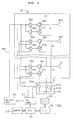
- FIG. 2 shows in block form a multibeam FM radar system according to the present invention.
- the multibeam FM radar system generally comprises an FM radar module 10 and a main radar circuit 20.
- the multibeam FM radar system is preferably installed on a motor vehicle (not shown).
- the FM radar module 10 comprises a dielectric substrate 11 and an antenna assembly 12 mounted thereon.
- the antenna assembly 12 comprises a plurality of (16 in the illustrated embodiment) transmitting/receiving channels A ⁇ P disposed on the dielectric substrate 11.
- the transmitting/receiving channels A ⁇ P comprise respective transmitting/receiving planar array antenna elements 12a ⁇ 12p and respective transmitting/receiving assemblies connected thereto.
- the transmitting/receiving assemblies have respective circulators 14a ⁇ 14p, respective selective transmission amplifiers 15a ⁇ 15p, respective selective reception amplifiers 16a ⁇ 16p, and respective mixers 17a ⁇ 17p.
- the transmitting/receiving channels A ⁇ P receive FM (frequency-modulated) millimeter-wave signals to be transmitted which are supplied from an FM signal generator 23 in the main radar circuit 20 through a microstrip line MS.
- the main radar circuit 20 comprises a CPU (central processing unit) 21, a channel controller 22, an FM signal generator 23, a selector 24, an A/D (analog-to-digital) converter 25, an FFT (fast Fourier transform) circuit 26, and a memory 27.
- the FM millimeter-wave signals from the FM signal generator 23 are supplied through the microstrip line MS to the respective selective transmission amplifiers 15a ⁇ 15p and the respective selective reception amplifiers 16a ⁇ 16p of the transmitting/receiving channels A ⁇ P, and are selectively amplified only in given periods successively by the respective selective transmission amplifiers 15a ⁇ 15p in the respective transmitting/receiving channels A ⁇ P according to channel control signals supplied from the channel controller 22.
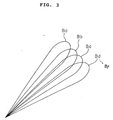
- the FM millimeter-wave signals amplified by the respective selective transmission amplifiers 15a ⁇ 15p are supplied through the respective circulators 14a ⁇ 14p to the respective planar array antenna elements 12a ⁇ 12p, which then radiate the FM millimeter-wave signals as FM signal beams Ba, Bb, Bc, Bd (see FIG. 3), for example, into space outside of the motor vehicle on which the multibeam FM radar system is installed.
- the directivity patterns of the respective planar array antenna elements 12a ⁇ 12p are substantially the same as each other, and have their central axes slightly shifted successively in a horizontal plane.
- Some of the FM millimeter-wave signals radiated as the FM signal beams out of the motor vehicle are reflected by objects such as motor vehicles, travel back to and are received by the planar array antenna elements 12a ⁇ 12p.
- the reflected signal beams which are received by the planar array antenna elements 12a ⁇ 12p are separated as FM echo signals from the transmitting channels by the circulators 14a ⁇ 14p, respectively.
- the separated FM echo signals are supplied to the respective received signal input terminals of the mixers 17a ⁇ 17p.
- the other local oscillator input terminals of the mixers 17a ⁇ 17p are supplied with amplified FM millimeter-wave signals from the selective reception amplifiers 16a ⁇ 16p which successively amplify FM millimeter-wave signals intermittently only in given periods according to channel control signals supplied from the channel controller 22.
- the selective reception amplifiers 16a ⁇ 16p function as respective switches as with the selective transmission amplifiers 15a ⁇ 15p.
- Beat signals outputted from respective output terminals of the mixers 17a ⁇ 17p are transmitted to the selector 24.
- the beat signals are amplified by respective amplifiers 24a ⁇ 24b.
- the amplified beat signals are then supplied through a signal line such as a coaxial cable to the A/D converter 25, which converts the beat signals into digital beat signals.
- the digital beat signals are then supplied to the FFT circuit 26, and converted thereby into a frequency spectrum that is then supplied to the CPU 21.
- the CPU 21 analyzes the frequency spectrum of the received FM echo signals supplied from the FFT circuit 26, calculates distances up to and relative speeds with respect to the motor vehicles which have produced the FM echo signals in the respective transmitting/receiving channels A ⁇ P and hence at respective bearings of the FM signal beams Ba ⁇ Bp, and generates a two-dimensional map of distances and bearings of the motor vehicles in a spatial distribution. Specifically, the CPU 21 pairs beat frequencies in rising and falling periods, and adds and subtracts the paired beat frequencies to detect distances up to and relative speeds with respect to motor vehicles that have reflected the FM signal beams. At this time, the CPU 21 pairs the beat frequencies while reflecting the detected result with respect each FM signal beam in the detected result with respect an adjacent FM signal beam. Such a beat frequency processing process of the CPU 21 will be described in detail below with reference to FIGS. 4A and 4B.
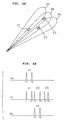
- the FM signal beams radiated from the planar array antenna elements 12a ⁇ 12p are represented by three adjacent beams Ba, Bb, Bc, and the motor vehicles running closely to each other are represented by three motor vehicles V1, V2, V3 which are positionally related to each other as shown in FIG. 4A.
- the motor vehicles V1 can be detected by the beam Ba
- all the motor vehicles V1, V2, V3 can be detected by the beam Bb
- only the motor vehicle V2 can be detected by the beam Bc.
- the frequency spectrums of beat signals produced with respect to the beams Ba, Bb, Bc include beat frequencies in the rising and falling periods as shown in FIG. 4B.
- the CPU 41 inspects the beat frequencies produced with respect to the beams Ba ⁇ Bc, pairs the beat frequencies with priority for those beams which involve fewer beat frequencies, and calculates distances up to and relative speeds with respect to the motor vehicles V1, V2, V3 based on the paired beat frequencies. Specifically, the CPU first processes the beat frequencies with respect to the beams Ba, Bc each involving two beat frequencies in preference to the beam Bb involving six beat frequencies.
- the CPU 21 Since the beam Ba involves only one pair of beat frequencies f1, f2, the CPU 21 assumes it as a pair of beat frequencies (fu, fd) generated by one motor vehicle, i.e., the motor vehicle V1. Then, the CPU 21 imparts a predetermined likelihood ratio ⁇ , which is given when only a pair of beat frequencies is produced by one beam, with respect to the beam Ba, and calculates a distance up to and a relative speed with respect to the motor vehicle V1 from the pair of beat frequencies according to the equations (3) ⁇ (6).
- the CPU 21 determines whether the calculated distance and relative speed are of reasonable values in view of the detecting capability of the multibeam FM radar system and the running capability of the motor vehicle, e.g., whether the motor vehicle exists at a far distance beyond the detecting capability of the multibeam FM radar system or not and whether the relative speed is impossibly high or not. If the calculated distance and relative speed are of reasonable values, then the CPU 21 imparts a likelihood ratio ⁇ greater than the likelihood ratio ⁇ to the calculated distance and relative speed.
- the CPU 21 assumes it as a pair of beat frequencies (fu, fd) generated by one motor vehicle, i.e., the motor vehicle V2. Then, the CPU 21 imparts the predetermined likelihood ratio ⁇ with respect to the beam Bc, and calculates a distance up to and a relative speed with respect to the motor vehicle V2 from the pair of beat frequencies according to the equations (3) ⁇ (6). The CPU 21 then determines whether the calculated distance and relative speed are of reasonable values. If the calculated distance and relative speed are of reasonable values, then the CPU 21 imparts the likelihood ratio ⁇ greater than the likelihood ratio ⁇ to the calculated distance and relative speed.
- the CPU 21 After having processed beat frequencies with respect to the beams Ba, Bc, the CPU 21 starts processing the beat frequencies with respect to the beat Bb.
- the CPU 21 detects that the beat frequencies f1, f2 with respect to the beam Bb are identical to the beat frequencies f1, f2 with respect to the beam Ba and that the likelihood ratio ⁇ has already been imparted with respect to the beam Ba. Then, the CPU 21 imparts a likelihood ratio ⁇ , greater than the likelihood ratio ⁇ , to the result obtained for the beam Ba with respect to the beat frequencies f1, f2, and excludes the pair of beat frequencies f1, f2 from further processing with respect to the beam Bb.
- the CPU 21 detects that the beat frequencies f3, f4 with respect to the beam Bb are identical to the beat frequencies f3, f4 with respect to the beam Bc and that the likelihood ratio ⁇ has already been imparted with respect to the beam Bc. Then, the CPU 21 imparts the likelihood ratio ⁇ , greater than the likelihood ratio ⁇ , to the result obtained for the beam Bc with respect to the beat frequencies f3, f4, and excludes the pair of beat frequencies f3, f4 from further processing with respect to the beam Bb.
- the CPU 21 detects that the beam Bb involves only a pair of frequencies f5, f6.
- the CPU 21 assumes it as a pair of beat frequencies (fu, fd) generated by one motor vehicle, i.e., the motor vehicle V3.
- the CPU 21 imparts the predetermined likelihood ratio ⁇ with respect to the beam Bc, and calculates a distance up to and a relative speed with respect to the motor vehicle V3 from the pair of beat frequencies according to the equations (3) ⁇ (6).
- the CPU 21 determines whether the calculated distance and relative speed are of reasonable values. If the calculated distance and relative speed are of reasonable values, then the CPU 21 imparts the likelihood ratio ⁇ greater than the likelihood ratio ⁇ to the calculated distance and relative speed.
- the CPU 21 produces data of the distance and relative speed with the likelihood ratio ⁇ with respect to each of the motor vehicles V1, V2, and data of the distance and relative speed with the likelihood ratio ⁇ with respect to the motor vehicle V3. After having processed the beat frequencies with respect to the beams, the CPU 21 erases all other data than the data to which likelihood ratios not less than the likelihood ratio ⁇ are imparted.
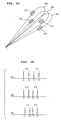
- FIG. 5A motor vehicles V1, V2 can be detected by the beam Ba
- motor vehicles V2, V3 can be detected by the beam Bb
- motor vehicles V3, V4 can be detected by the beam Bc. If the relative speeds between the motor vehicle on which the multibeam FM radar system is installed and the motor vehicles V1, V2, V3, V4 are not nil, then the frequency spectrums of beat signals produced with respect to the beams Ba, Bb, Bc include beat frequencies in the rising and falling periods as shown in FIG. 5B.
- the CPU 21 compares the beat frequencies produced with respect to the beam Ba and the beat frequencies produced with respect to the beam Bb. If the CPU 21 recognizes that a pair of beat frequencies f1, f2 produced with respect to the beam Ba and a pair of beat frequencies f1, f2 produced with respect to the beam Bb are the same as each other, then the CPU 21 assumes it as a pair of beat frequencies (fu, fd) generated by one motor vehicle, i.e., the motor vehicle V2.
- the CPU 21 imparts a predetermined likelihood ratio ⁇ , which is given when such a pair of beat frequencies is produced by both of adjacent beams, with respect to the beams Ba, Bb, and calculates a distance up to and a relative speed with respect to the motor vehicle V2 from the pair of beat frequencies according to the equations (3) ⁇ (6).
- the CPU 21 determines whether the calculated distance and relative speed are of reasonable values in view of the detecting capability of the multibeam FM radar system and the running capability of the motor vehicle. If the calculated distance and relative speed are of reasonable values, then the CPU 21 imparts a likelihood ratio ⁇ greater than the likelihood ratio ⁇ to the calculated distance and relative speed.
- the CPU 21 excludes the pair of beat frequencies f1, f2, to which the likelihood ratio ⁇ has been imparted, from the beat frequencies with respect to the beams Ba, Bb.
- the CPU 21 compares the beat frequencies produced with respect to the beam Bb and the beat frequencies produced with respect to the beam Bc. If the CPU 21 recognizes that a pair of beat frequencies f5, f6 produced with respect to the beam Bb and a pair of beat frequencies f5, f6 produced with respect to the beam Bc are the same as each other, then the CPU 21 assumes it as a pair of beat frequencies (fu, fd) generated by one motor vehicle, i.e., the motor vehicle V3. Then, the CPU 21 imparts the predetermined likelihood ratio ⁇ with respect to the beams Bb, Bc, and calculates a distance up to and a relative speed with respect to the motor vehicle Vc from the pair of beat frequencies according to the equations (3) ⁇ (6).
- the CPU 21 determines whether the calculated distance and relative speed are of reasonable values in view of the detecting capability of the multibeam FM radar system and the running capability of the motor vehicle. If the calculated distance and relative speed are of reasonable values, then the CPU 21 imparts the likelihood ratio ⁇ greater than the likelihood ratio ⁇ to the calculated distance and relative speed.
- the CPU 21 excludes the pair of beat frequencies f5, f6, to which the likelihood ratio ⁇ has been imparted, from the beat frequencies with respect to the beams Bb, Bc.
- the CPU 21 assumes it as a pair of beat frequencies (fu, fd) generated by one motor vehicle, i.e., the motor vehicle V1. Then, the CPU 21 imparts a predetermined likelihood ratio ⁇ , which is given when only a pair of beat frequencies is produced by one beam, with respect to the beam Ba, and calculates a distance up to and a relative speed with respect to the motor vehicle V1 from the pair of beat frequencies according to the equations (3) ⁇ (6). The CPU 21 then determines whether the calculated distance and relative speed are of reasonable values. If the calculated distance and relative speed are of reasonable values, then the CPU 21 imparts a likelihood ratio ⁇ greater than the likelihood ratio ⁇ to the calculated distance and relative speed.
- the CPU 21 assumes it as a pair of beat frequencies (fu, fd) generated by one motor vehicle, i.e., the motor vehicle V4. Then, the CPU 21 imparts the predetermined likelihood ratio ⁇ , which is given when only a pair of beat frequencies is produced by one beam, with respect to the beam Bc, and calculates a distance up to and a relative speed with respect to the motor vehicle V4 from the pair of beat frequencies according to the equations (3) ⁇ (6). The CPU 21 then determines whether the calculated distance and relative speed are of reasonable values. If the calculated distance and relative speed are of reasonable values, then the CPU 21 imparts the likelihood ratio ⁇ greater than the likelihood ratio ⁇ to the calculated distance and relative speed.
- FIG. 6A a motor vehicle V1 can be detected by the beams Ba, Bb, and a motor vehicle V2 can be detected by the beams Bb, Bc. If the relative speeds between the motor vehicle on which the multibeam FM radar system is installed and the motor vehicles V1, V2 are not nil, then the frequency spectrums of beat signals produced with respect to the beams Ba, Bb, Bc have beat frequencies in the rising and falling periods as shown in FIG. 5B. It is assumed that beat frequencies indicated by the dotted lines in FIG. 5B are missing and are not actually generated due to noise or the like.
- no beat frequencies f2, f3 are present in the frequency spectrum of beat signals produced with respect to the beam Bb.
- the CPU 21 detects pairs of beat frequencies f1, f2 and f3, f4 from the frequency spectrums of beat signals produced with respect to the beams Ba, Bc, with a predetermined likelihood ratio ⁇ . If distances up to and relative speeds with respect to the motor vehicles, which have been calculated from those beat frequencies, are of reasonable values, then the CPU 21 imparts the distances and relative speeds a likelihood ratio ⁇ higher than the likelihood ratio ⁇ .
- the CPU 12 pairs the beat frequencies f1, f4 with respect to the beam Bb and calculates a relative speed from a Doppler shift caused by the beat frequencies f1, f4. Since the calculated relative speed is abnormally high, the CPU 12 decides that the pairing of the beat frequencies f1, f4 is inappropriate.
- the CPU 12 makes a final decision in view of another possibility that a motor vehicle with no relative speed may exist in a position at a distance determined from the beat frequencies f1, f4 and also still another possibility that the beat frequencies f2, f3 are missing from the frequency spectrum of beat signals produced with respect to the beam Bb.
- the CPU 21 then compensates for a beat frequency f2 from the frequency spectrum relative to the beam Ba, and calculates a distance and a relative speed from the paired beat frequencies f1, f2.
- the calculated likelihood ratio ⁇ is greater if a single beat frequency f1 is present in the frequency spectrum relative to an adjacent beam, e.g., if only a beat frequency f1 is present in the frequency spectrum relative to the adjacent beam Bc.
- a missing beat frequency is compensated for in order to match beat frequencies in the frequency spectrums relative to adjacent beams with each other for the pairing of the beat frequencies.
- a beat frequency having the same value as the single beat frequency may be added to provide two beat frequencies in order to match beat frequencies in the frequency spectrums relative to adjacent beams with each other.
- the multibeam FM radar system operates based on the fact that it radiates and receives a plurality of FM signal beams, and pairs beat frequencies in order to match detected results with respect to the beams with each other or pairs beat frequencies successively from those beams which have fewer beat frequencies.
- the multibeam FM radar system reflects the detected result with respect to each FM signal beam in the detected result with respect to an adjacent FM signal beam.
- the multibeam FM radar system is thus capable of detecting distances up to a plurality of closely running motor vehicles and relative speeds thereof by distinguishing the motor vehicles accurately from each other.
- a multibeam FM radar system has an FM radar module for transmitting beams of FM signals whose frequencies linearly vary in rising and falling periods, in respective different directions with adjacent ones of the beams overlapping each other, receiving echo signals, and mixing the FM signals and the echo signals into beat signals.
- the multibeam FM radar system also has a main radar circuit including a central processing unit for producing pairs of frequencies of the beat signals in the rising and falling periods with respect to the beams, and processing the pairs of the frequencies to detect distances up to and/or relative speeds with respect to objects which have produced the echo signals, while reflecting a detected result with respect each of the beams in a detected result with respect an adjacent one of the beams.
Landscapes
- Engineering & Computer Science (AREA)
- Radar, Positioning & Navigation (AREA)
- Remote Sensing (AREA)
- Computer Networks & Wireless Communication (AREA)
- Physics & Mathematics (AREA)
- General Physics & Mathematics (AREA)
- Radar Systems Or Details Thereof (AREA)
Applications Claiming Priority (3)
| Application Number | Priority Date | Filing Date | Title |
|---|---|---|---|
| JP13955396 | 1996-05-09 | ||
| JP139553/96 | 1996-05-09 | ||
| JP8139553A JP3012805B2 (ja) | 1996-05-09 | 1996-05-09 | Fmレーダ装置 |
Publications (3)
| Publication Number | Publication Date |
|---|---|
| EP0806681A2 true EP0806681A2 (de) | 1997-11-12 |
| EP0806681A3 EP0806681A3 (de) | 1999-11-10 |
| EP0806681B1 EP0806681B1 (de) | 2003-12-10 |
Family
ID=15247953
Family Applications (1)
| Application Number | Title | Priority Date | Filing Date |
|---|---|---|---|
| EP97106907A Expired - Lifetime EP0806681B1 (de) | 1996-05-09 | 1997-04-25 | Mehrstrahl-Radarsystem |
Country Status (4)
| Country | Link |
|---|---|
| US (1) | US5945939A (de) |
| EP (1) | EP0806681B1 (de) |
| JP (1) | JP3012805B2 (de) |
| DE (1) | DE69726639T2 (de) |
Cited By (5)
| Publication number | Priority date | Publication date | Assignee | Title |
|---|---|---|---|---|
| EP0981059A3 (de) * | 1998-08-18 | 2000-11-22 | Toyota Jidosha Kabushiki Kaisha | FM-CW Radarvorrichtung |
| EP1094336A3 (de) * | 1999-10-19 | 2001-08-01 | Honda Giken Kogyo Kabushiki Kaisha | Objekterkennungsgerät |
| EP1041398A3 (de) * | 1999-03-31 | 2002-01-02 | Denso Corporation | Radagerät mit Verwendung von digitaler Strahlformungstechnik |
| EP2009464A4 (de) * | 2006-03-01 | 2011-05-04 | Toyota Motor Co Ltd | Objektdetektionseinrichtung |
| DE19842827B4 (de) * | 1998-09-18 | 2015-08-06 | Volkswagen Ag | Precrashsensierungssystem |
Families Citing this family (17)
| Publication number | Priority date | Publication date | Assignee | Title |
|---|---|---|---|---|
| JP3942722B2 (ja) * | 1998-02-16 | 2007-07-11 | 本田技研工業株式会社 | 車載レーダ装置 |
| DE10163653A1 (de) * | 2001-12-21 | 2003-07-03 | Bosch Gmbh Robert | Vorrichtung für ein Radarsystem |
| JP3753071B2 (ja) * | 2002-01-07 | 2006-03-08 | 株式会社村田製作所 | レーダ |
| GB0228731D0 (en) * | 2002-12-10 | 2003-01-15 | Trw Ltd | Frequency shift keying radar with ambiguity detection |
| JP2005156337A (ja) * | 2003-11-26 | 2005-06-16 | Hitachi Ltd | 車載用レーダ装置 |
| DE102006028465A1 (de) * | 2006-06-21 | 2007-12-27 | Valeo Schalter Und Sensoren Gmbh | Kraftfahrzeug-Radarsystem und Verfahren zur Bestimmung von Geschwindigkeiten und Entfernungen von Objekten relativ zu dem einen Radarsystem |
| JP4769684B2 (ja) * | 2006-10-12 | 2011-09-07 | 株式会社デンソーアイティーラボラトリ | 電子走査式レーダ装置 |
| US7973700B2 (en) * | 2008-01-31 | 2011-07-05 | Denso International America, Inc. | Dual transmitting antenna system |
| JP2009271008A (ja) * | 2008-05-09 | 2009-11-19 | Honda Motor Co Ltd | 物体検知装置 |
| CN101320085B (zh) * | 2008-07-21 | 2012-07-25 | 哈尔滨工业大学 | 基于后向投影算法的超宽带穿墙点目标定位成像方法 |
| DE102010041755A1 (de) * | 2010-09-30 | 2012-04-05 | Siemens Aktiengesellschaft | Radarsystem |
| JP5653726B2 (ja) * | 2010-11-12 | 2015-01-14 | 株式会社デンソー | レーダ装置 |
| EP2492709A1 (de) * | 2011-02-25 | 2012-08-29 | Nederlandse Organisatie voor toegepast -natuurwetenschappelijk onderzoek TNO | FMCW-Radarsystem |
| KR102128544B1 (ko) * | 2012-12-26 | 2020-06-30 | 현대모비스 주식회사 | 레이더 장치 및 이에 적용되는 신호처리방법 |
| EP2977784B1 (de) * | 2013-03-18 | 2018-08-01 | Panasonic Corporation | Radarvorrichtung |
| US9784829B2 (en) * | 2015-04-06 | 2017-10-10 | GM Global Technology Operations LLC | Wheel detection and its application in object tracking and sensor registration |
| WO2020090681A1 (ja) * | 2018-11-02 | 2020-05-07 | 株式会社村田製作所 | アンテナ装置、移動体、及びターゲット判別方法 |
Family Cites Families (12)
| Publication number | Priority date | Publication date | Assignee | Title |
|---|---|---|---|---|
| JP2665834B2 (ja) * | 1991-02-15 | 1997-10-22 | 本田技研工業株式会社 | Fmレーダ |
| US5268692A (en) * | 1991-03-14 | 1993-12-07 | Grosch Theodore O | Safe stopping distance detector, antenna and method |
| JP2765773B2 (ja) * | 1991-11-26 | 1998-06-18 | 富士通テン株式会社 | ミリ波レーダ距離速度測定装置 |
| JP2679907B2 (ja) * | 1991-12-02 | 1997-11-19 | 富士通テン株式会社 | ミリ波レーダ距離速度測定装置 |
| JP2567332B2 (ja) * | 1993-02-17 | 1996-12-25 | 本田技研工業株式会社 | 時分割型レーダシステム |
| JP2989428B2 (ja) * | 1993-06-17 | 1999-12-13 | 本田技研工業株式会社 | 時分割型fmレーダシステム |
| GB2283631B (en) * | 1993-11-06 | 1998-04-29 | Roke Manor Research | Radar apparatus |
| JP3256374B2 (ja) * | 1994-05-27 | 2002-02-12 | 本田技研工業株式会社 | マルチビーム・レーダ装置 |
| JP3308734B2 (ja) * | 1994-10-13 | 2002-07-29 | 本田技研工業株式会社 | レーダーモジュール |
| JP2768439B2 (ja) * | 1994-11-08 | 1998-06-25 | 本田技研工業株式会社 | Fm−cw方式マルチビームレーダー装置 |
| JP3627389B2 (ja) * | 1995-09-28 | 2005-03-09 | 株式会社デンソー | レーダ装置 |
| JP3104599B2 (ja) * | 1995-11-24 | 2000-10-30 | トヨタ自動車株式会社 | Fm−cwレーダ装置 |
-
1996
- 1996-05-09 JP JP8139553A patent/JP3012805B2/ja not_active Expired - Fee Related
-
1997
- 1997-04-25 EP EP97106907A patent/EP0806681B1/de not_active Expired - Lifetime
- 1997-04-25 DE DE69726639T patent/DE69726639T2/de not_active Expired - Lifetime
- 1997-05-06 US US08/852,155 patent/US5945939A/en not_active Expired - Lifetime
Cited By (6)
| Publication number | Priority date | Publication date | Assignee | Title |
|---|---|---|---|---|
| EP0981059A3 (de) * | 1998-08-18 | 2000-11-22 | Toyota Jidosha Kabushiki Kaisha | FM-CW Radarvorrichtung |
| DE19842827B4 (de) * | 1998-09-18 | 2015-08-06 | Volkswagen Ag | Precrashsensierungssystem |
| EP1041398A3 (de) * | 1999-03-31 | 2002-01-02 | Denso Corporation | Radagerät mit Verwendung von digitaler Strahlformungstechnik |
| EP1094336A3 (de) * | 1999-10-19 | 2001-08-01 | Honda Giken Kogyo Kabushiki Kaisha | Objekterkennungsgerät |
| US6518916B1 (en) | 1999-10-19 | 2003-02-11 | Honda Giken Kogyo Kabushiki Kaisha | Object recognition apparatus |
| EP2009464A4 (de) * | 2006-03-01 | 2011-05-04 | Toyota Motor Co Ltd | Objektdetektionseinrichtung |
Also Published As
| Publication number | Publication date |
|---|---|
| DE69726639D1 (de) | 2004-01-22 |
| DE69726639T2 (de) | 2004-10-14 |
| JPH09304519A (ja) | 1997-11-28 |
| US5945939A (en) | 1999-08-31 |
| EP0806681B1 (de) | 2003-12-10 |
| JP3012805B2 (ja) | 2000-02-28 |
| EP0806681A3 (de) | 1999-11-10 |
Similar Documents
| Publication | Publication Date | Title |
|---|---|---|
| EP0806681B1 (de) | Mehrstrahl-Radarsystem | |
| US6292129B1 (en) | Structure of radar system with multi-receiver channel | |
| US6067048A (en) | Radar apparatus | |
| EP0499270B1 (de) | FM-Radarsystem | |
| JP3433417B2 (ja) | レーダ装置 | |
| EP0777133B1 (de) | FM-CW-Radar-Anlage zum Messen der relativen Geschwindigkeit und der Entfernung eines Objekts | |
| JP3302848B2 (ja) | 車載レーダー装置 | |
| US6049301A (en) | Surveillance apparatus and method for the detection of radio receivers | |
| JP2768439B2 (ja) | Fm−cw方式マルチビームレーダー装置 | |
| EP0859241B1 (de) | Time-Sharing-Radarsystem | |
| US6859168B2 (en) | Radar apparatus | |
| EP1253441A1 (de) | Entfernungsmessgerät | |
| US7714772B2 (en) | Transmit-receive FM-CW radar apparatus | |
| JP2000258524A (ja) | レーダ装置 | |
| JP2802671B2 (ja) | ミリ波レーダ送受信機 | |
| JPH1184001A (ja) | 車載レーダ装置及びこれを用いた車両の自動制御システム | |
| JP3530081B2 (ja) | マルチビームfmレーダ装置 | |
| JP2964947B2 (ja) | 時分割型レーダシステム | |
| US11796671B2 (en) | Transmission scheme for implementing code division multiple access in a radar system | |
| JP2875509B2 (ja) | Fmレーダ装置 | |
| JP3463747B2 (ja) | Fm−cwレーダ装置 | |
| JP2009162521A (ja) | レ−ダ装置 |
Legal Events
| Date | Code | Title | Description |
|---|---|---|---|
| PUAI | Public reference made under article 153(3) epc to a published international application that has entered the european phase |
Free format text: ORIGINAL CODE: 0009012 |
|
| AK | Designated contracting states |
Kind code of ref document: A2 Designated state(s): DE FR GB |
|
| PUAL | Search report despatched |
Free format text: ORIGINAL CODE: 0009013 |
|
| AK | Designated contracting states |
Kind code of ref document: A3 Designated state(s): DE FR GB |
|
| 17P | Request for examination filed |
Effective date: 19991201 |
|
| 17Q | First examination report despatched |
Effective date: 20010510 |
|
| GRAH | Despatch of communication of intention to grant a patent |
Free format text: ORIGINAL CODE: EPIDOS IGRA |
|
| GRAS | Grant fee paid |
Free format text: ORIGINAL CODE: EPIDOSNIGR3 |
|
| GRAA | (expected) grant |
Free format text: ORIGINAL CODE: 0009210 |
|
| AK | Designated contracting states |
Kind code of ref document: B1 Designated state(s): DE FR GB |
|
| REG | Reference to a national code |
Ref country code: GB Ref legal event code: FG4D |
|
| REF | Corresponds to: |
Ref document number: 69726639 Country of ref document: DE Date of ref document: 20040122 Kind code of ref document: P |
|
| ET | Fr: translation filed | ||
| PLBE | No opposition filed within time limit |
Free format text: ORIGINAL CODE: 0009261 |
|
| STAA | Information on the status of an ep patent application or granted ep patent |
Free format text: STATUS: NO OPPOSITION FILED WITHIN TIME LIMIT |
|
| 26N | No opposition filed |
Effective date: 20040913 |
|
| PGFP | Annual fee paid to national office [announced via postgrant information from national office to epo] |
Ref country code: GB Payment date: 20070416 Year of fee payment: 11 |
|
| PGFP | Annual fee paid to national office [announced via postgrant information from national office to epo] |
Ref country code: FR Payment date: 20070425 Year of fee payment: 11 |
|
| GBPC | Gb: european patent ceased through non-payment of renewal fee |
Effective date: 20080425 |
|
| REG | Reference to a national code |
Ref country code: FR Ref legal event code: ST Effective date: 20081231 |
|
| PG25 | Lapsed in a contracting state [announced via postgrant information from national office to epo] |
Ref country code: FR Free format text: LAPSE BECAUSE OF NON-PAYMENT OF DUE FEES Effective date: 20080430 |
|
| PG25 | Lapsed in a contracting state [announced via postgrant information from national office to epo] |
Ref country code: GB Free format text: LAPSE BECAUSE OF NON-PAYMENT OF DUE FEES Effective date: 20080425 |
|
| PGFP | Annual fee paid to national office [announced via postgrant information from national office to epo] |
Ref country code: DE Payment date: 20110420 Year of fee payment: 15 |
|
| REG | Reference to a national code |
Ref country code: DE Ref legal event code: R119 Ref document number: 69726639 Country of ref document: DE Effective date: 20121101 |
|
| PG25 | Lapsed in a contracting state [announced via postgrant information from national office to epo] |
Ref country code: DE Free format text: LAPSE BECAUSE OF NON-PAYMENT OF DUE FEES Effective date: 20121101 |