EP0806578A1 - Pièce d'étanchéité pour le transfer d'un liquide caloporteur à un système rotatif de pression - Google Patents
Pièce d'étanchéité pour le transfer d'un liquide caloporteur à un système rotatif de pression Download PDFInfo
- Publication number
- EP0806578A1 EP0806578A1 EP97104456A EP97104456A EP0806578A1 EP 0806578 A1 EP0806578 A1 EP 0806578A1 EP 97104456 A EP97104456 A EP 97104456A EP 97104456 A EP97104456 A EP 97104456A EP 0806578 A1 EP0806578 A1 EP 0806578A1
- Authority
- EP
- European Patent Office
- Prior art keywords
- sealing head
- rotor
- condensate
- head according
- sealing
- Prior art date
- Legal status (The legal status is an assumption and is not a legal conclusion. Google has not performed a legal analysis and makes no representation as to the accuracy of the status listed.)
- Granted
Links
Images


Classifications
-
- F—MECHANICAL ENGINEERING; LIGHTING; HEATING; WEAPONS; BLASTING
- F16—ENGINEERING ELEMENTS AND UNITS; GENERAL MEASURES FOR PRODUCING AND MAINTAINING EFFECTIVE FUNCTIONING OF MACHINES OR INSTALLATIONS; THERMAL INSULATION IN GENERAL
- F16C—SHAFTS; FLEXIBLE SHAFTS; ELEMENTS OR CRANKSHAFT MECHANISMS; ROTARY BODIES OTHER THAN GEARING ELEMENTS; BEARINGS
- F16C13/00—Rolls, drums, discs, or the like; Bearings or mountings therefor
- F16C13/02—Bearings
-
- F—MECHANICAL ENGINEERING; LIGHTING; HEATING; WEAPONS; BLASTING
- F16—ENGINEERING ELEMENTS AND UNITS; GENERAL MEASURES FOR PRODUCING AND MAINTAINING EFFECTIVE FUNCTIONING OF MACHINES OR INSTALLATIONS; THERMAL INSULATION IN GENERAL
- F16L—PIPES; JOINTS OR FITTINGS FOR PIPES; SUPPORTS FOR PIPES, CABLES OR PROTECTIVE TUBING; MEANS FOR THERMAL INSULATION IN GENERAL
- F16L27/00—Adjustable joints; Joints allowing movement
- F16L27/08—Adjustable joints; Joints allowing movement allowing adjustment or movement only about the axis of one pipe
- F16L27/0804—Adjustable joints; Joints allowing movement allowing adjustment or movement only about the axis of one pipe the fluid passing axially from one joint element to another
- F16L27/0808—Adjustable joints; Joints allowing movement allowing adjustment or movement only about the axis of one pipe the fluid passing axially from one joint element to another the joint elements extending coaxially for some distance from their point of separation
- F16L27/0824—Adjustable joints; Joints allowing movement allowing adjustment or movement only about the axis of one pipe the fluid passing axially from one joint element to another the joint elements extending coaxially for some distance from their point of separation with ball or roller bearings
- F16L27/0828—Adjustable joints; Joints allowing movement allowing adjustment or movement only about the axis of one pipe the fluid passing axially from one joint element to another the joint elements extending coaxially for some distance from their point of separation with ball or roller bearings having radial bearings
-
- F—MECHANICAL ENGINEERING; LIGHTING; HEATING; WEAPONS; BLASTING
- F16—ENGINEERING ELEMENTS AND UNITS; GENERAL MEASURES FOR PRODUCING AND MAINTAINING EFFECTIVE FUNCTIONING OF MACHINES OR INSTALLATIONS; THERMAL INSULATION IN GENERAL
- F16C—SHAFTS; FLEXIBLE SHAFTS; ELEMENTS OR CRANKSHAFT MECHANISMS; ROTARY BODIES OTHER THAN GEARING ELEMENTS; BEARINGS
- F16C2361/00—Apparatus or articles in engineering in general
-
- Y—GENERAL TAGGING OF NEW TECHNOLOGICAL DEVELOPMENTS; GENERAL TAGGING OF CROSS-SECTIONAL TECHNOLOGIES SPANNING OVER SEVERAL SECTIONS OF THE IPC; TECHNICAL SUBJECTS COVERED BY FORMER USPC CROSS-REFERENCE ART COLLECTIONS [XRACs] AND DIGESTS
- Y10—TECHNICAL SUBJECTS COVERED BY FORMER USPC
- Y10T—TECHNICAL SUBJECTS COVERED BY FORMER US CLASSIFICATION
- Y10T137/00—Fluid handling
- Y10T137/6416—With heating or cooling of the system
- Y10T137/6579—Circulating fluid in heat exchange relationship
-
- Y—GENERAL TAGGING OF NEW TECHNOLOGICAL DEVELOPMENTS; GENERAL TAGGING OF CROSS-SECTIONAL TECHNOLOGIES SPANNING OVER SEVERAL SECTIONS OF THE IPC; TECHNICAL SUBJECTS COVERED BY FORMER USPC CROSS-REFERENCE ART COLLECTIONS [XRACs] AND DIGESTS
- Y10—TECHNICAL SUBJECTS COVERED BY FORMER USPC
- Y10T—TECHNICAL SUBJECTS COVERED BY FORMER US CLASSIFICATION
- Y10T137/00—Fluid handling
- Y10T137/8593—Systems
- Y10T137/86268—With running joint between movable parts of system
Definitions
- the invention relates to a sealing head for transporting a heat transfer medium, in particular for supplying steam to a rotating pressure system, such as a drying drum, heating roller or the like, and then removing the condensate, consisting of a tubular rotor connected to the pressure system and a roller bearing on the Rotor arranged stationary sealing head housing with at least one connecting piece for a connecting line carrying the heat transfer medium, the rotor being in open connection with the connecting piece via the interior of the sealing head housing acted upon by the heat transfer medium and axially between the connecting piece and the roller bearings against the rotor the wall of the sealing head housing sealing primary sealing element is arranged, a secondary seal between the rotor and the wall of the sealing head housing is connected on the atmosphere side axially towards the rolling bearings.
- a rotating pressure system such as a drying drum, heating roller or the like
- Sealing heads of this type when using liquid heat transfer media are known from practice.
- the heat transfer medium ensures lubrication in the area of the primary sealing element, so that despite the usually high speeds of the printing system and the high temperatures of the heat transfer medium, the wear is kept low and the sealing function of the sealing element is impaired as little as possible.
- the invention is therefore based on the object of designing a sealing head of the type mentioned in such a way that an adequate lubricating effect is ensured in the region of the primary sealing element even when steam is used as the heat transfer medium.
- annularly extending condensate space is arranged around the rotor, which is connected via at least one overflow channel with that of the heat transfer medium pressurized interior is in connection and which is in heat-conducting contact with a cooling system.
- the advantage achieved by the invention consists essentially in the fact that a condensate is formed directly from the steam serving as the heat transfer medium, which acts on the primary sealing element from the side facing away from the interior of the sealing head housing. Due to the direct connection between the interior and the condensate chamber, a pressure equilibrium is set, whereby no one-sided force loads due to different pressure loads act on the primary sealing element. In this way, sufficient lubrication of the primary sealing element, which is otherwise particularly stressed, is ensured despite the use of steam as the heat transfer medium.
- the primary sealing element is designed as an annular lip seal or as a mechanical seal and the secondary seal as a mechanical seal.
- the ring lip seal expediently has a plurality of ring lips arranged axially one behind the other.
- the invention provides that the primary sealing element is enclosed on its side facing the interior by an insulating washer.
- the sealing element is advantageously in one Ring rebate of the insulating washer inserted.
- the rotor in an expedient embodiment of the invention has a double-walled design in the region extending over the two seals.
- a sleeve part is arranged in the condensate space that divides the condensate space into a radially inner one and the outer, axially extending flow channel, the inner and outer flow channels each being axially connected to one another at the ends.
- the sleeve part can advantageously be provided with radially outwardly directed, axially extending and evenly distributed separating webs, which form the outer flow channels between them.
- the invention provides that fixed delivery devices for the condensate circulate within the sleeve part on the rotor and generate a delivery pressure for the circulation of the condensate in the flow channels.
- these conveying members can be moved from one to the lateral surface of the Mechanical bearing bearing ring arranged conveying thread can be formed.
- the cooling system is expediently formed by an annular chamber which surrounds the condensate space and through which cooling water flows and which is connected to the cooling water circuit for the counter ring cooling of the slide ring bearing.
- the annular chamber is advantageously provided with annular grooves extending in the direction of the condensate space.
- the overflow channels be opened or blocked by nipples that can be inserted radially into the sealing head housing, whereby only the topmost vertical overflow channel in the installed position is open.
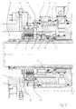
- the sealing head 1 shown in the drawing is used to supply a heat transfer medium, in particular in the form of steam, to a rotating pressure system 2, for example a drying drum, heating roller or the like, which is only indicated in the drawing with its connecting device.
- a rotating pressure system 2 for example a drying drum, heating roller or the like
- the sealing head 1 consists of a tubular rotor 3 connected to the pressure system 2 and a stationary sealing head housing 5 arranged on roller bearings 4 on the rotor 3.
- the sealing head housing 5 has at least one connecting piece 5 'for a connecting line which carries the heat transfer medium and is not shown in the drawing .
- the rotor 3 is in open connection with the connecting piece 5 'via the interior 8 of the sealing head housing 5 acted upon by the heat transfer medium. As a result, the heat transfer medium can reach the pressure system 2 through the connection piece 5 'and the rotor 3.
- a primary sealing element 6, which seals the rotor 3 against the wall of the sealing head housing 5, is arranged axially between the connecting piece 5 'and the roller bearings 4, axially in the direction a secondary seal 7 between the rotor 3 and the wall of the sealing head housing 5 is connected downstream to the rolling bearings 4 on the atmosphere side.
- a condensate space 9 extending in a ring around the rotor 3 is arranged axially between the secondary seal 7 and the primary sealing element 6.
- the condensate chamber 9 is connected to the interior 8 via at least one, preferably via four overflow channels 10.
- the condensate chamber 9 is in heat-conducting contact with a cooling system 11.
- the vaporous heat transfer medium can enter the condensate chamber 9 through the overflow channel 10 and condense there under the influence of the cooling system 11.
- the condensate which thus also comes into contact with the primary sealing element 6, prevents this sealing element 6 from running dry, and thus acts as a lubricant.
- the primary sealing element 6 can be designed as an annular lip seal, wherein, as can also be seen from FIGS. 1 and 2, the annular lip seal is expediently constructed from a plurality of axially arranged annular lips.
- the secondary seal 7 is designed as a conventional mechanical seal.
- the primary sealing element 6 is enclosed on its side facing the interior 8 by an insulating washer 12 which prevents heat flow from the interior 8 to the condensate space 9.
- the sealing element 6 is inserted into an annular fold of the insulating washer 12.
- the rotor 3 is double-walled in the region extending over the two seals 6, 7.
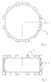
- a sleeve part 13 Arranged in the condensate space 9 is a sleeve part 13 shown in FIGS. 4 and 5, which divides the condensate space 9 into a radially inner 14 'and outer 14'', each axially extending flow channel.
- the inner and outer flow channels 14 ', 14'' are in each case axially connected to one another. A circulating flow is therefore basically possible.
- the sleeve part 13 is provided with radially outwardly directed, axially extending and evenly distributed dividers 13 '. These form the outer flow channels 14 ′′ between them on the outer peripheral surface.
- conveying elements for the condensate are provided on the rotor 3, which rotate with the rotor 3 and generate a conveying pressure for the circulation of the condensate in the flow channels 14 ', 14''.
- These conveying members are formed by a conveying thread, which is only indicated as a line 15 in the usual representation in FIG. 1, the conveying thread on the lateral surface of the mechanical seal 7 bearing ring 16 is arranged.
- the cooling system 11 is formed by an annular chamber 17 which surrounds the condensate chamber 9 and through which cooling water flows.
- This annular chamber 17 is also connected to the cooling water circuit, which is used for cooling the counter ring of the slide ring bearing 7.
- This annular chamber can, as shown in the drawing in FIG. 2, be provided with annular grooves 18 extending in the direction of the condensate chamber 9, as a result of which the inner surface is enlarged, thus achieving a better cooling effect.
- the overflow channels 10 are to be opened or shut off by means of radially into the sealing head housing 5, which can be used alternatively and are designed differently.
- the nipples 19 are therefore only inserted after the final assembly of the sealing head 1 in such a way that only the uppermost overflow channel 10, which is vertical in the installed position, is opened, while the others are closed.
Landscapes
- Engineering & Computer Science (AREA)
- General Engineering & Computer Science (AREA)
- Mechanical Engineering (AREA)
- Mechanical Sealing (AREA)
- Rolls And Other Rotary Bodies (AREA)
- Turbine Rotor Nozzle Sealing (AREA)
- Drying Of Solid Materials (AREA)
Applications Claiming Priority (2)
| Application Number | Priority Date | Filing Date | Title |
|---|---|---|---|
| DE19618661 | 1996-05-09 | ||
| DE19618661A DE19618661C1 (de) | 1996-05-09 | 1996-05-09 | Dichtkopf zum Transport eines Wärmeträgermediums zu einem rotierenden Drucksystem |
Publications (2)
| Publication Number | Publication Date |
|---|---|
| EP0806578A1 true EP0806578A1 (fr) | 1997-11-12 |
| EP0806578B1 EP0806578B1 (fr) | 2003-09-24 |
Family
ID=7793823
Family Applications (1)
| Application Number | Title | Priority Date | Filing Date |
|---|---|---|---|
| EP97104456A Expired - Lifetime EP0806578B1 (fr) | 1996-05-09 | 1997-03-15 | Pièce d'étanchéité pour le transfer d'un liquide caloporteur à un système rotatif de pression |
Country Status (4)
| Country | Link |
|---|---|
| US (1) | US5778971A (fr) |
| EP (1) | EP0806578B1 (fr) |
| DE (1) | DE19618661C1 (fr) |
| ES (1) | ES2202505T3 (fr) |
Cited By (2)
| Publication number | Priority date | Publication date | Assignee | Title |
|---|---|---|---|---|
| CN102410415A (zh) * | 2011-08-25 | 2012-04-11 | 江苏腾旋科技股份有限公司 | 高温高速旋转接头 |
| EP3828431A1 (fr) * | 2019-11-26 | 2021-06-02 | Christian Maier GmbH & Co. KG Maschinenfabrik | Passage tournant |
Families Citing this family (14)
| Publication number | Priority date | Publication date | Assignee | Title |
|---|---|---|---|---|
| DE19707876C2 (de) * | 1997-02-27 | 2002-09-26 | Voith Paper Patent Gmbh | Walzenanordnung |
| DE19747555A1 (de) * | 1997-10-28 | 1999-04-29 | Voith Sulzer Papiertech Patent | Heiz- und/oder kühlbarer Zylinder |
| SE515396C2 (sv) * | 1999-05-12 | 2001-07-30 | Abb Ab | En svivel för flexibel transport av en fluid |
| US6164316A (en) * | 1999-12-23 | 2000-12-26 | Deublin Company | High temperature rotating union |
| TW427449U (en) * | 2000-01-28 | 2001-03-21 | Ind Tech Res Inst | Cooling device for hollow screw |
| DE10205790A1 (de) * | 2002-02-13 | 2003-08-28 | Maier Christian Masch | Dichtkopf zum Zuführen eines Wärmeträgermediums |
| NO316470B1 (no) * | 2002-05-08 | 2009-11-16 | Advanced Prod & Loading As | Anordning for sammenkopling av rørledninger som fører fluid under trykk |
| US20040163709A1 (en) * | 2003-02-24 | 2004-08-26 | Baugh Benton F. | Fluid swivel with cooling porting |
| ITUD20030167A1 (it) * | 2003-08-08 | 2005-02-09 | De Longhi Spa | Raccordo coassiale a giunto. |
| CN100387368C (zh) * | 2005-11-17 | 2008-05-14 | 王溥岚 | 水循环交换器 |
| US8172738B2 (en) * | 2006-01-18 | 2012-05-08 | 3M Innovative Properties Company | Dead-shaft roller with aerostatic rotary union |
| ITPR20060062A1 (it) * | 2006-07-03 | 2008-01-04 | Cft Spa | Sistema per creare una barriera sterile e lubrificare e/o refrigerare parti mobili in impianti di sterilizzazione uht. |
| US10947992B2 (en) * | 2015-08-17 | 2021-03-16 | Pedro Arnulfo Sarmiento | Convectors |
| US11953126B1 (en) * | 2023-04-21 | 2024-04-09 | Princetel, Inc. | Fluid rotary joint assembly suitable for high rotational speed |
Citations (2)
| Publication number | Priority date | Publication date | Assignee | Title |
|---|---|---|---|---|
| US4965920A (en) * | 1989-07-07 | 1990-10-30 | Phillips Petroleum Company | Fluid heated roll apparatus and method |
| EP0448730A1 (fr) * | 1990-02-23 | 1991-10-02 | Christian Maier GmbH & Co. Maschinenfabrik | Pièce d'étanchéité pour le transfert d'un liquide caloporteur à une machine rotative de pression |
Family Cites Families (7)
| Publication number | Priority date | Publication date | Assignee | Title |
|---|---|---|---|---|
| US1953525A (en) * | 1931-06-13 | 1934-04-03 | Young George Harold | Siphon exhaust for drier rolls |
| US2331615A (en) * | 1942-06-22 | 1943-10-12 | Rotary Seal Company | Sealed coupling |
| US3638606A (en) * | 1969-11-21 | 1972-02-01 | Gen Electric | Apparatus for controlling the coating of selected surfaces of an article of manufacture |
| US3704669A (en) * | 1970-07-15 | 1972-12-05 | Stevens Corp | Vibrating roller with means for circulating a cooling fluid for use in bearing and drive gear lubrication |
| US4230928A (en) * | 1978-12-18 | 1980-10-28 | Wolff Manufacturing Company | Method and machine for rebuilding track roller assemblies |
| DE3417093A1 (de) * | 1984-05-09 | 1985-11-14 | Küsters, Eduard, 4150 Krefeld | Drehanschlusskopf fuer heizbare bzw. kuehlbare walzen |
| DE3812533A1 (de) * | 1988-04-15 | 1989-10-26 | Josef Seelen | Abdichtung fuer blasrohr oder welle |
-
1996
- 1996-05-09 DE DE19618661A patent/DE19618661C1/de not_active Expired - Lifetime
-
1997
- 1997-03-15 ES ES97104456T patent/ES2202505T3/es not_active Expired - Lifetime
- 1997-03-15 EP EP97104456A patent/EP0806578B1/fr not_active Expired - Lifetime
- 1997-05-09 US US08/853,644 patent/US5778971A/en not_active Expired - Lifetime
Patent Citations (2)
| Publication number | Priority date | Publication date | Assignee | Title |
|---|---|---|---|---|
| US4965920A (en) * | 1989-07-07 | 1990-10-30 | Phillips Petroleum Company | Fluid heated roll apparatus and method |
| EP0448730A1 (fr) * | 1990-02-23 | 1991-10-02 | Christian Maier GmbH & Co. Maschinenfabrik | Pièce d'étanchéité pour le transfert d'un liquide caloporteur à une machine rotative de pression |
Cited By (2)
| Publication number | Priority date | Publication date | Assignee | Title |
|---|---|---|---|---|
| CN102410415A (zh) * | 2011-08-25 | 2012-04-11 | 江苏腾旋科技股份有限公司 | 高温高速旋转接头 |
| EP3828431A1 (fr) * | 2019-11-26 | 2021-06-02 | Christian Maier GmbH & Co. KG Maschinenfabrik | Passage tournant |
Also Published As
| Publication number | Publication date |
|---|---|
| DE19618661C1 (de) | 1997-10-09 |
| US5778971A (en) | 1998-07-14 |
| ES2202505T3 (es) | 2004-04-01 |
| EP0806578B1 (fr) | 2003-09-24 |
Similar Documents
| Publication | Publication Date | Title |
|---|---|---|
| DE19618661C1 (de) | Dichtkopf zum Transport eines Wärmeträgermediums zu einem rotierenden Drucksystem | |
| EP0340503B1 (fr) | Rouleau chauffé | |
| DE19613609C2 (de) | Axialkolbenmaschine mit internem Spülkreislauf | |
| DE4238147C2 (de) | Radial-Nadellager-Baueinheit mit integrierter Radial-Axialabdichtung und ggf. Axialabstützung | |
| EP1069362B1 (fr) | Jonction rotative pour milieux alternés | |
| EP1327802B1 (fr) | Dispositif de joint hydraulique | |
| DE2037387A1 (de) | Lageranordnung mit flexiblen Laby nnthdichtungen | |
| DE1475601A1 (de) | Mechanische Druckstufendichtung | |
| DE2364256A1 (de) | Druckmittelbetaetigte dichtung | |
| DE3127122C2 (de) | Flüssigkeitsgekühlter Ventilsitz für ein Auslassventil einer Kolbenbrennkraftmaschine | |
| DE1260249B (de) | Stopfbuechse zur Abdichtung gegen gasfoermige Medien | |
| DE1425955B2 (de) | Axiallager | |
| DE3907154A1 (de) | Oelschmiersystem fuer die lagerung eines wellenzapfens in einer rotierenden welle | |
| DE2731313A1 (de) | Flexible dichtung und dichtungskonstruktion | |
| EP0220558A2 (fr) | Distributeur de fluide pour cylindre de serrage rotatif | |
| DE2138362A1 (de) | Wellendichtung für Druckmittelbehandlungsmaschinen | |
| DE1600651A1 (de) | Wellendichtung | |
| DE102017106942A1 (de) | Hydrodynamische Kupplung | |
| EP1336807B1 (fr) | Pièce d'étanchéité pour le transfert d'un milieu calporteur | |
| DE3115193C2 (de) | Radial-Wälzlager mit Ölbadschmierung | |
| DE102016124283A1 (de) | Hydrodynamische Kupplung | |
| DE2817878B1 (de) | Einoelwalze | |
| DE20007849U1 (de) | Radial-Axial-Wälzlager | |
| DE102010017620B4 (de) | Dichtungsanordnung und Walze | |
| DE2911000A1 (de) | Drehdurchfuehrung fuer die einleitung stroemungsfaehiger medien in ein rotierendes maschinenteil |
Legal Events
| Date | Code | Title | Description |
|---|---|---|---|
| PUAI | Public reference made under article 153(3) epc to a published international application that has entered the european phase |
Free format text: ORIGINAL CODE: 0009012 |
|
| 17P | Request for examination filed |
Effective date: 19970910 |
|
| AK | Designated contracting states |
Kind code of ref document: A1 Designated state(s): ES FI FR GB IT NL |
|
| RBV | Designated contracting states (corrected) |
Designated state(s): ES FI FR GB IT NL |
|
| REG | Reference to a national code |
Ref country code: DE Ref legal event code: 8566 |
|
| 17Q | First examination report despatched |
Effective date: 20000306 |
|
| RIC1 | Information provided on ipc code assigned before grant |
Ipc: 7F 16L 27/08 B Ipc: 7F 16C 13/00 A |
|
| GRAH | Despatch of communication of intention to grant a patent |
Free format text: ORIGINAL CODE: EPIDOS IGRA |
|
| GRAS | Grant fee paid |
Free format text: ORIGINAL CODE: EPIDOSNIGR3 |
|
| GRAA | (expected) grant |
Free format text: ORIGINAL CODE: 0009210 |
|
| AK | Designated contracting states |
Kind code of ref document: B1 Designated state(s): ES FI FR GB IT NL |
|
| REG | Reference to a national code |
Ref country code: GB Ref legal event code: FG4D Free format text: NOT ENGLISH |
|
| GBT | Gb: translation of ep patent filed (gb section 77(6)(a)/1977) | ||
| REG | Reference to a national code |
Ref country code: ES Ref legal event code: FG2A Ref document number: 2202505 Country of ref document: ES Kind code of ref document: T3 |
|
| ET | Fr: translation filed | ||
| PLBE | No opposition filed within time limit |
Free format text: ORIGINAL CODE: 0009261 |
|
| STAA | Information on the status of an ep patent application or granted ep patent |
Free format text: STATUS: NO OPPOSITION FILED WITHIN TIME LIMIT |
|
| 26N | No opposition filed |
Effective date: 20040625 |
|
| REG | Reference to a national code |
Ref country code: FR Ref legal event code: PLFP Year of fee payment: 20 |
|
| PGFP | Annual fee paid to national office [announced via postgrant information from national office to epo] |
Ref country code: FR Payment date: 20151209 Year of fee payment: 20 |
|
| PGFP | Annual fee paid to national office [announced via postgrant information from national office to epo] |
Ref country code: NL Payment date: 20160324 Year of fee payment: 20 Ref country code: ES Payment date: 20160125 Year of fee payment: 20 |
|
| PGFP | Annual fee paid to national office [announced via postgrant information from national office to epo] |
Ref country code: GB Payment date: 20160322 Year of fee payment: 20 Ref country code: FI Payment date: 20160316 Year of fee payment: 20 |
|
| PGFP | Annual fee paid to national office [announced via postgrant information from national office to epo] |
Ref country code: IT Payment date: 20160330 Year of fee payment: 20 |
|
| REG | Reference to a national code |
Ref country code: NL Ref legal event code: MK Effective date: 20170314 |
|
| REG | Reference to a national code |
Ref country code: GB Ref legal event code: PE20 Expiry date: 20170314 |
|
| PG25 | Lapsed in a contracting state [announced via postgrant information from national office to epo] |
Ref country code: GB Free format text: LAPSE BECAUSE OF EXPIRATION OF PROTECTION Effective date: 20170314 |
|
| REG | Reference to a national code |
Ref country code: ES Ref legal event code: FD2A Effective date: 20180508 |
|
| PG25 | Lapsed in a contracting state [announced via postgrant information from national office to epo] |
Ref country code: ES Free format text: LAPSE BECAUSE OF EXPIRATION OF PROTECTION Effective date: 20170316 |