EP0806578B1 - Pièce d'étanchéité pour le transfer d'un liquide caloporteur à un système rotatif de pression - Google Patents
Pièce d'étanchéité pour le transfer d'un liquide caloporteur à un système rotatif de pression Download PDFInfo
- Publication number
- EP0806578B1 EP0806578B1 EP97104456A EP97104456A EP0806578B1 EP 0806578 B1 EP0806578 B1 EP 0806578B1 EP 97104456 A EP97104456 A EP 97104456A EP 97104456 A EP97104456 A EP 97104456A EP 0806578 B1 EP0806578 B1 EP 0806578B1
- Authority
- EP
- European Patent Office
- Prior art keywords
- sealing head
- rotor
- condensate
- sealing
- head according
- Prior art date
- Legal status (The legal status is an assumption and is not a legal conclusion. Google has not performed a legal analysis and makes no representation as to the accuracy of the status listed.)
- Expired - Lifetime
Links
- 238000007789 sealing Methods 0.000 title claims description 79
- 238000001816 cooling Methods 0.000 claims description 14
- 238000005096 rolling process Methods 0.000 claims description 7
- 239000000498 cooling water Substances 0.000 claims description 5
- 210000002445 nipple Anatomy 0.000 claims description 4
- 238000001035 drying Methods 0.000 claims description 3
- 238000010438 heat treatment Methods 0.000 claims description 2
- 238000010276 construction Methods 0.000 claims 1
- 239000002826 coolant Substances 0.000 claims 1
- 230000013011 mating Effects 0.000 claims 1
- 238000000638 solvent extraction Methods 0.000 claims 1
- 230000000694 effects Effects 0.000 description 2
- 230000001050 lubricating effect Effects 0.000 description 2
- 238000005461 lubrication Methods 0.000 description 2
- 230000015572 biosynthetic process Effects 0.000 description 1
- 238000009434 installation Methods 0.000 description 1
- 239000007788 liquid Substances 0.000 description 1
- 239000000314 lubricant Substances 0.000 description 1
- 230000002093 peripheral effect Effects 0.000 description 1
Images


Classifications
-
- F—MECHANICAL ENGINEERING; LIGHTING; HEATING; WEAPONS; BLASTING
- F16—ENGINEERING ELEMENTS AND UNITS; GENERAL MEASURES FOR PRODUCING AND MAINTAINING EFFECTIVE FUNCTIONING OF MACHINES OR INSTALLATIONS; THERMAL INSULATION IN GENERAL
- F16C—SHAFTS; FLEXIBLE SHAFTS; ELEMENTS OR CRANKSHAFT MECHANISMS; ROTARY BODIES OTHER THAN GEARING ELEMENTS; BEARINGS
- F16C13/00—Rolls, drums, discs, or the like; Bearings or mountings therefor
- F16C13/02—Bearings
-
- F—MECHANICAL ENGINEERING; LIGHTING; HEATING; WEAPONS; BLASTING
- F16—ENGINEERING ELEMENTS AND UNITS; GENERAL MEASURES FOR PRODUCING AND MAINTAINING EFFECTIVE FUNCTIONING OF MACHINES OR INSTALLATIONS; THERMAL INSULATION IN GENERAL
- F16L—PIPES; JOINTS OR FITTINGS FOR PIPES; SUPPORTS FOR PIPES, CABLES OR PROTECTIVE TUBING; MEANS FOR THERMAL INSULATION IN GENERAL
- F16L27/00—Adjustable joints; Joints allowing movement
- F16L27/08—Adjustable joints; Joints allowing movement allowing adjustment or movement only about the axis of one pipe
- F16L27/0804—Adjustable joints; Joints allowing movement allowing adjustment or movement only about the axis of one pipe the fluid passing axially from one joint element to another
- F16L27/0808—Adjustable joints; Joints allowing movement allowing adjustment or movement only about the axis of one pipe the fluid passing axially from one joint element to another the joint elements extending coaxially for some distance from their point of separation
- F16L27/0824—Adjustable joints; Joints allowing movement allowing adjustment or movement only about the axis of one pipe the fluid passing axially from one joint element to another the joint elements extending coaxially for some distance from their point of separation with ball or roller bearings
- F16L27/0828—Adjustable joints; Joints allowing movement allowing adjustment or movement only about the axis of one pipe the fluid passing axially from one joint element to another the joint elements extending coaxially for some distance from their point of separation with ball or roller bearings having radial bearings
-
- F—MECHANICAL ENGINEERING; LIGHTING; HEATING; WEAPONS; BLASTING
- F16—ENGINEERING ELEMENTS AND UNITS; GENERAL MEASURES FOR PRODUCING AND MAINTAINING EFFECTIVE FUNCTIONING OF MACHINES OR INSTALLATIONS; THERMAL INSULATION IN GENERAL
- F16C—SHAFTS; FLEXIBLE SHAFTS; ELEMENTS OR CRANKSHAFT MECHANISMS; ROTARY BODIES OTHER THAN GEARING ELEMENTS; BEARINGS
- F16C2361/00—Apparatus or articles in engineering in general
-
- Y—GENERAL TAGGING OF NEW TECHNOLOGICAL DEVELOPMENTS; GENERAL TAGGING OF CROSS-SECTIONAL TECHNOLOGIES SPANNING OVER SEVERAL SECTIONS OF THE IPC; TECHNICAL SUBJECTS COVERED BY FORMER USPC CROSS-REFERENCE ART COLLECTIONS [XRACs] AND DIGESTS
- Y10—TECHNICAL SUBJECTS COVERED BY FORMER USPC
- Y10T—TECHNICAL SUBJECTS COVERED BY FORMER US CLASSIFICATION
- Y10T137/00—Fluid handling
- Y10T137/6416—With heating or cooling of the system
- Y10T137/6579—Circulating fluid in heat exchange relationship
-
- Y—GENERAL TAGGING OF NEW TECHNOLOGICAL DEVELOPMENTS; GENERAL TAGGING OF CROSS-SECTIONAL TECHNOLOGIES SPANNING OVER SEVERAL SECTIONS OF THE IPC; TECHNICAL SUBJECTS COVERED BY FORMER USPC CROSS-REFERENCE ART COLLECTIONS [XRACs] AND DIGESTS
- Y10—TECHNICAL SUBJECTS COVERED BY FORMER USPC
- Y10T—TECHNICAL SUBJECTS COVERED BY FORMER US CLASSIFICATION
- Y10T137/00—Fluid handling
- Y10T137/8593—Systems
- Y10T137/86268—With running joint between movable parts of system
Definitions
- the invention relates to a sealing head for transport a heat transfer medium in the form of steam to one rotating printing system, like a drying drum, Heat roller or the like, and then Drainage of the condensate, consisting of one to the Tubular rotor and pressure system connected one arranged on the rotor via roller bearings stationary sealing head housing with at least one Connection piece for the heat transfer medium leading connecting line, the rotor over the from Heat transfer medium acted on the interior of the Sealing head housing in open connection with the Connection piece stands and axially between the Connection piece and the rolling bearings against the rotor primary wall sealing the sealing head housing Sealing element is arranged, the axially in the direction towards the rolling bearings a sealing to the atmosphere, secondary seal between the rotor and the wall of the Sealing head housing is connected downstream, and in Sealing head housing axially between the secondary Seal and the primary sealing element itself arranged in a ring around the rotor is.
- the Heat transfer medium ensures lubrication in the Area of the primary sealing element, so that despite the usually high speeds of the printing system and the high temperatures of the heat transfer medium Wear kept low and thus the sealing function the sealing element affected as little as possible becomes.
- the invention has for its object a To design the sealing head of the type mentioned at the beginning that even when using steam as Heat transfer medium has a sufficient lubricating effect in the Ensured area of the primary sealing element is.
- this object is achieved by that the space between the primary sealing element and the secondary seal is a condensate space that in heat-conducting contact with a cooling system and the via at least one overflow channel with that of Heat transfer medium charged inside Connection is established.
- the advantage achieved by the invention is essential in that directly from the as Steam used as a heat transfer medium is a condensate is formed by the the interior of the Sealing head housing facing away from that primary sealing element acts.
- the ring lip seal points to increase the sealing effect expediently several, axially one behind the other arranged ring lips on.
- the invention provides that the primary Sealing element on its interior facing Side is enclosed by an insulating washer.
- the Sealing element is advantageously in one Ring rebate of the insulating washer inserted.
- the rotor is more appropriate Embodiment of the invention in which the two seals extending area double-walled educated.
- a sufficient amount of condensate for To convey sealing element on the other hand sufficient condensate formation by cooling the Steam on the wall cooled by the cooling system achieve, it is provided that in the condensate chamber a sleeve part is arranged, the condensate space in a radially inner and outer, axially running flow channel divided, the inner and outer flow channels each axially are connected at the ends.
- the sleeve part can advantageously with radially outward, axially extending and arranged evenly distributed over the circumference Separators are provided, which between them form outer flow channels.
- the Invention before that within the sleeve part on the rotor fixed conveying devices for the condensate circulate and a delivery pressure for the circulation of the Generate condensate in the flow channels.
- the conveying bodies can Invention of one on the lateral surface of the Mechanical bearing bearing ring arranged Conveying thread be formed.
- the cooling system is conveniently one of the Condensate chamber enclosing cooling water flowed through annular chamber formed on the Cooling water circuit for the counter ring cooling of the Mechanical bearing is connected.
- the ring chamber advantageously with in the direction of the condensate chamber extending ring grooves.
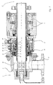
- the sealing head 1 shown in the drawing serves for supplying a heat transfer medium, in particular in Form of steam to a rotating pressure system 2, for example a drying drum, heating roller or the like, that in the drawing only with his Connection device is indicated.
- a rotating pressure system 2 for example a drying drum, heating roller or the like
- the sealing head 1 consists of a Pressure system 2 connected tubular rotor 3 and a roller bearing 4 arranged on the rotor 3 stationary sealing head housing 5.
- Das Sealing head housing 5 has at least one Connection piece 5 'for the heat transfer medium leading, not shown in the drawing Lead.
- the rotor 3 is above that of the heat transfer medium acted upon interior 8 of the sealing head housing 5 in open connection with the connecting piece 5 '. Thereby can the heat transfer medium through the Connection piece 5 'and the rotor 3 in that Get printing system 2.
- connection piece 5 'and Rolling bearings 4 Axially between the connection piece 5 'and Rolling bearings 4 is a rotor 3 against the wall of the Sealing head housing 5 sealing primary Sealing element 6 arranged axially in the direction to the rolling bearings 4 towards the atmosphere secondary seal 7 between the rotor 3 and the wall the sealing head housing 5 is connected downstream.
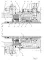
- the sealing head housing 5 is axially between the secondary seal 7 and the primary Sealing element 6 a ring around the rotor 3rd extending condensate chamber 9 arranged.
- the Condensate chamber 9 is above at least one, preferably via four overflow channels 10 with the Interior 8 in connection.
- the Condensate chamber 9 in heat-conducting contact with a Cooling system 11. This allows the vapor Heat transfer medium through the overflow channel 10 in the Enter the condensate chamber 9 and there under the influence of the cooling system 11 condense.
- the condensate that thus also in contact with the primary Sealing element 6 comes, prevents dry running this sealing element 6, so acts as Lubricant.
- the condensate chamber 9 in connection stands with the interior 8 of the sealing head housing 5, exist between the axially two sides of the primary Sealing element 6 no pressure differences, so that in any case there is no axial application of force.
- This allows the primary sealing element 6 as Ring lip seal to be formed, how how this also results from FIGS. 1 and 2, the Ring lip seal expediently from several ring lips arranged axially one behind the other is.
- the secondary seal 7 is, however, as usual Mechanical seal designed.
- the primary sealing element 6 is on its Interior 8 facing side from one Insulated washer 12, the heat flow from Interior 8 forth to the condensate chamber 9 prevented.
- the Sealing element 6 is in an annular fold Insulating washer 12 inserted.
- the rotor 3 is in the extending over the two seals 6, 7 Double-walled area.
- the condensate chamber 9 in a radially inner 14 'and outer 14 ", each axially extending flow channel divided.
- the inner and outer flow channels 14 ', 14 " are axially end-to-end in connection. This is basically one circulating flow possible.
- the sleeve part 13 is with radially outward, axially extending and arranged evenly distributed over the circumference Separators 13 'provided. These form between themselves the outer peripheral surface Flow channels 14 ".
- the cooling system 11 is of the condensate space 9 enclosing annular chamber 17 formed by Cooling water is flowing through.
- This annular chamber 17 is connected to the cooling water circuit, which the Counter ring cooling of the slide ring bearing 7 is used.
- This The annular chamber can, as in the drawing in FIG. 2 shown with itself towards the condensate chamber 9 extending ring grooves 18 may be provided, whereby the inner surface enlarged, thus a better Cooling effect is achieved.
- nipples 19 are therefore inserted only after final assembly of the sealing head 1 in the Way that only the topmost in the installed position Overflow channel 10 opened, the rest against are closed.
Landscapes
- Engineering & Computer Science (AREA)
- General Engineering & Computer Science (AREA)
- Mechanical Engineering (AREA)
- Mechanical Sealing (AREA)
- Rolls And Other Rotary Bodies (AREA)
- Turbine Rotor Nozzle Sealing (AREA)
- Drying Of Solid Materials (AREA)
Claims (13)
- Joint tournant pour le transfert d'un fluide caloporteur sous forme de vapeur dans un système sous pression (2) rotatif, tel qu'un cylindre de séchage, un cylindre de chauffage ou similaire, et l'évacuation consécutive du condensat, comprenant un rotor (3) tubulaire relié au système sous pression (2) et un corps (5) de joint tournant, qui est monté stationnaire sur le rotor (3) par l'intermédiaire d'un palier à roulement (4) et présente au moins une pièce de raccord (5') pour une conduite de liaison transportant le fluide caloporteur, le rotor (3) communiquant librement avec la pièce de raccord (5') via la chambre intérieure (8) du corps (5) de joint tournant, alimentée en fluide caloporteur, un élément d'étanchéité (6) primaire, qui assure l'étanchéité entre le rotor (5) et la paroi du corps (5) de joint tournant, étant disposé axialement entre la pièce de raccord (5') et le palier à roulement (4), un joint secondaire (7) qui assure l'étanchéité avec l'atmosphère étant disposé à la suite de celui-ci dans la direction axiale, entre le rotor (3) et la paroi du corps (5) de joint tournant, et une chambre, qui s'étend en anneau autour du rotor (3), étant disposée dans le corps (5) de joint tournant, axialement entre le joint secondaire (7) et l'élément d'étanchéité primaire (6), caractérisé en ce que la chambre entre l'élément d'étanchéité primaire (6) et le joint secondaire (7) est une chambre à condensat (9) qui est en contact conducteur de chaleur avec un système de refroidissement (11) et communique via au moins un canal d'écoulement (10) avec la chambre intérieure (8) alimentée en fluide caloporteur.
- Joint tournant selon la revendication 1, caractérisé en ce que l'élément d'étanchéité (6) primaire est conformé en joint annulaire à lèvres ou en garniture d'étanchéité à joint glissant et le joint secondaire (7) est conformé en garniture d'étanchéité à joint glissant.
- Joint tournant selon la revendication 2, caractérisé en ce que le joint annulaire à lèvres présente plusieurs lèvres annulaires disposées l'une derrière l'autre dans la direction axiale.
- Joint tournant selon une des revendications 1 à 3, caractérisé en ce que l'élément d'étanchéité (6) primaire, du côté tourné vers la chambre intérieure (8), est entouré d'une bague isolante (12).
- Joint tournant selon la revendication 4, caractérisé en ce que l'élément d'étanchéité (6) primaire est monté dans une feuillure annulaire de la bague isolante (12).
- Joint tournant selon une des revendications 1 à 5, caractérisé en ce que le rotor (3) dans la zone qui comprend les deux joints (6, 7), est à double paroi.
- Joint tournant selon une des revendications 1 à 6, caractérisé en ce qu'une pièce en forme de manchon (13) est disposée dans la chambre à condensat (9) et divise ladite chambre à condensat (9) en un canal d'écoulement intérieur (14') et un canal d'écoulement extérieur (14"), les canaux d'écoulement intérieur et extérieur (14', 14") communiquant l'un avec l'autre, chacun au niveau de son extrémité axiale.
- Joint tournant selon la revendication 7, caractérisé en ce que la - pièce en forme de manchon (13) est pourvue de cloisons (13') orientées radialement vers l'extérieur, qui s'étendent dans la direction axiale, sont réparties régulièrement sur le pourtour et forment entre elles les canaux d'écoulement extérieurs (14").
- Joint tournant selon la revendication 7 ou 8, caractérisé en ce qu'à l'intérieur de la pièce en forme de manchon (13), des organes de transport pour le condensat, solidaires du rotor (3), sont animés d'un mouvement de rotation et produisent une pression de refoulement pour la circulation du condensat dans les canaux d'écoulement (14', 14").
- Joint tournant selon la revendication 9, caractérisé en ce que les organes de transport sont formés d'un filet transporteur (15) aménagé sur la surface extérieure de la bague de roulement (16) portant la garniture d'étanchéité à joint glissant (7).
- Joint tournant selon une des revendications 1 à 10, caractérisé en ce que le système de refroidissement (11) est formé d'une chambre annulaire (17) balayée par de l'eau de refroidissement qui entoure la chambre à condensat (9) et est connectée au circuit d'eau de refroidissement pour le refroidissement de la bague d'appui du palier (7) à coussinet lisse.
- Joint tournant selon la revendication 11, caractérisé en ce que la chambre annulaire (17) est pourvue de gorges annulaires (18) qui s'étendent en direction de la chambre à condensat (9).
- Joint tournant selon une des revendications 1 à 12, caractérisé en ce que les canaux d'écoulement (10) peuvent être ouverts ou fermés au moyen de bouchons (19) insérés de manière sélective, radialement, dans le corps de joint tournant (5), seul le canal d'écoulement (10) le plus haut dans la position de montage verticale étant ouvert.
Applications Claiming Priority (2)
| Application Number | Priority Date | Filing Date | Title |
|---|---|---|---|
| DE19618661 | 1996-05-09 | ||
| DE19618661A DE19618661C1 (de) | 1996-05-09 | 1996-05-09 | Dichtkopf zum Transport eines Wärmeträgermediums zu einem rotierenden Drucksystem |
Publications (2)
| Publication Number | Publication Date |
|---|---|
| EP0806578A1 EP0806578A1 (fr) | 1997-11-12 |
| EP0806578B1 true EP0806578B1 (fr) | 2003-09-24 |
Family
ID=7793823
Family Applications (1)
| Application Number | Title | Priority Date | Filing Date |
|---|---|---|---|
| EP97104456A Expired - Lifetime EP0806578B1 (fr) | 1996-05-09 | 1997-03-15 | Pièce d'étanchéité pour le transfer d'un liquide caloporteur à un système rotatif de pression |
Country Status (4)
| Country | Link |
|---|---|
| US (1) | US5778971A (fr) |
| EP (1) | EP0806578B1 (fr) |
| DE (1) | DE19618661C1 (fr) |
| ES (1) | ES2202505T3 (fr) |
Families Citing this family (16)
| Publication number | Priority date | Publication date | Assignee | Title |
|---|---|---|---|---|
| DE19707876C2 (de) * | 1997-02-27 | 2002-09-26 | Voith Paper Patent Gmbh | Walzenanordnung |
| DE19747555A1 (de) * | 1997-10-28 | 1999-04-29 | Voith Sulzer Papiertech Patent | Heiz- und/oder kühlbarer Zylinder |
| SE515396C2 (sv) * | 1999-05-12 | 2001-07-30 | Abb Ab | En svivel för flexibel transport av en fluid |
| US6164316A (en) * | 1999-12-23 | 2000-12-26 | Deublin Company | High temperature rotating union |
| TW427449U (en) * | 2000-01-28 | 2001-03-21 | Ind Tech Res Inst | Cooling device for hollow screw |
| DE10205790A1 (de) * | 2002-02-13 | 2003-08-28 | Maier Christian Masch | Dichtkopf zum Zuführen eines Wärmeträgermediums |
| NO316470B1 (no) * | 2002-05-08 | 2009-11-16 | Advanced Prod & Loading As | Anordning for sammenkopling av rørledninger som fører fluid under trykk |
| US20040163709A1 (en) * | 2003-02-24 | 2004-08-26 | Baugh Benton F. | Fluid swivel with cooling porting |
| ITUD20030167A1 (it) * | 2003-08-08 | 2005-02-09 | De Longhi Spa | Raccordo coassiale a giunto. |
| CN100387368C (zh) * | 2005-11-17 | 2008-05-14 | 王溥岚 | 水循环交换器 |
| US8172738B2 (en) * | 2006-01-18 | 2012-05-08 | 3M Innovative Properties Company | Dead-shaft roller with aerostatic rotary union |
| ITPR20060062A1 (it) * | 2006-07-03 | 2008-01-04 | Cft Spa | Sistema per creare una barriera sterile e lubrificare e/o refrigerare parti mobili in impianti di sterilizzazione uht. |
| CN102410415A (zh) * | 2011-08-25 | 2012-04-11 | 江苏腾旋科技股份有限公司 | 高温高速旋转接头 |
| US10947992B2 (en) * | 2015-08-17 | 2021-03-16 | Pedro Arnulfo Sarmiento | Convectors |
| DE102019218288A1 (de) * | 2019-11-26 | 2021-05-27 | Christian Maier GmbH & Co. KG, Maschinenfabrik | Drehdurchführung |
| US11953126B1 (en) * | 2023-04-21 | 2024-04-09 | Princetel, Inc. | Fluid rotary joint assembly suitable for high rotational speed |
Citations (1)
| Publication number | Priority date | Publication date | Assignee | Title |
|---|---|---|---|---|
| US1953525A (en) * | 1931-06-13 | 1934-04-03 | Young George Harold | Siphon exhaust for drier rolls |
Family Cites Families (8)
| Publication number | Priority date | Publication date | Assignee | Title |
|---|---|---|---|---|
| US2331615A (en) * | 1942-06-22 | 1943-10-12 | Rotary Seal Company | Sealed coupling |
| US3638606A (en) * | 1969-11-21 | 1972-02-01 | Gen Electric | Apparatus for controlling the coating of selected surfaces of an article of manufacture |
| US3704669A (en) * | 1970-07-15 | 1972-12-05 | Stevens Corp | Vibrating roller with means for circulating a cooling fluid for use in bearing and drive gear lubrication |
| US4230928A (en) * | 1978-12-18 | 1980-10-28 | Wolff Manufacturing Company | Method and machine for rebuilding track roller assemblies |
| DE3417093A1 (de) * | 1984-05-09 | 1985-11-14 | Küsters, Eduard, 4150 Krefeld | Drehanschlusskopf fuer heizbare bzw. kuehlbare walzen |
| DE3812533A1 (de) * | 1988-04-15 | 1989-10-26 | Josef Seelen | Abdichtung fuer blasrohr oder welle |
| US4965920A (en) * | 1989-07-07 | 1990-10-30 | Phillips Petroleum Company | Fluid heated roll apparatus and method |
| ES2035665T3 (es) * | 1990-02-23 | 1993-04-16 | Christian Maier Gmbh & Co. Maschinenfabrik | Cabezal de estanqueidad para la alimentacion de un medio portador de calor a un sistema a presion giratorio. |
-
1996
- 1996-05-09 DE DE19618661A patent/DE19618661C1/de not_active Expired - Lifetime
-
1997
- 1997-03-15 ES ES97104456T patent/ES2202505T3/es not_active Expired - Lifetime
- 1997-03-15 EP EP97104456A patent/EP0806578B1/fr not_active Expired - Lifetime
- 1997-05-09 US US08/853,644 patent/US5778971A/en not_active Expired - Lifetime
Patent Citations (1)
| Publication number | Priority date | Publication date | Assignee | Title |
|---|---|---|---|---|
| US1953525A (en) * | 1931-06-13 | 1934-04-03 | Young George Harold | Siphon exhaust for drier rolls |
Also Published As
| Publication number | Publication date |
|---|---|
| DE19618661C1 (de) | 1997-10-09 |
| EP0806578A1 (fr) | 1997-11-12 |
| US5778971A (en) | 1998-07-14 |
| ES2202505T3 (es) | 2004-04-01 |
Similar Documents
| Publication | Publication Date | Title |
|---|---|---|
| EP0806578B1 (fr) | Pièce d'étanchéité pour le transfer d'un liquide caloporteur à un système rotatif de pression | |
| EP0340503B1 (fr) | Rouleau chauffé | |
| DE19613609C2 (de) | Axialkolbenmaschine mit internem Spülkreislauf | |
| DE2037387A1 (de) | Lageranordnung mit flexiblen Laby nnthdichtungen | |
| DE29704386U1 (de) | Vierreihiges Kegelrollenlager, insbesondere für Arbeitswalzen von Walzgerüsten | |
| CH651899A5 (de) | Antrieb mit einem motor und einem spannungswellen-getriebe. | |
| EP1327802B1 (fr) | Dispositif de joint hydraulique | |
| DE3127122C2 (de) | Flüssigkeitsgekühlter Ventilsitz für ein Auslassventil einer Kolbenbrennkraftmaschine | |
| DE9103935U1 (de) | Lagergehäuse für ein mehrreihiges Wälzlager oder für mehrere koaxial nebeneinander liegende Wälzlager | |
| DE3140425A1 (de) | Vorrichtung zum erzeugen und/oder bearbeiten von bahnmaterial | |
| DE1782548B2 (de) | Vollmantel-Schneckenzentrifuge | |
| EP0448730B1 (fr) | Pièce d'étanchéité pour le transfert d'un liquide caloporteur à une machine rotative de pression | |
| DE1260249B (de) | Stopfbuechse zur Abdichtung gegen gasfoermige Medien | |
| EP3595954B1 (fr) | Transmission, en particulier pour la chaîne cinématique de véhicules ferroviaires | |
| EP0220558A2 (fr) | Distributeur de fluide pour cylindre de serrage rotatif | |
| DE10302271A1 (de) | Einbaustück zur Aufnahme eines Walzenzapfens | |
| DE2351494A1 (de) | Hydrostatisches radiallager | |
| EP1336807B1 (fr) | Pièce d'étanchéité pour le transfert d'un milieu calporteur | |
| DE19753104A1 (de) | Schmiervorrichtung für ein Linearwälzlager | |
| DE102021208704A1 (de) | Gehäusedeckel und Planetengetriebe | |
| DE3115193C2 (de) | Radial-Wälzlager mit Ölbadschmierung | |
| DE69002759T3 (de) | Schmierung für durchbiegungseinstellwalze. | |
| DE2817878B1 (de) | Einoelwalze | |
| DE20007849U1 (de) | Radial-Axial-Wälzlager | |
| DE102010017620B4 (de) | Dichtungsanordnung und Walze |
Legal Events
| Date | Code | Title | Description |
|---|---|---|---|
| PUAI | Public reference made under article 153(3) epc to a published international application that has entered the european phase |
Free format text: ORIGINAL CODE: 0009012 |
|
| 17P | Request for examination filed |
Effective date: 19970910 |
|
| AK | Designated contracting states |
Kind code of ref document: A1 Designated state(s): ES FI FR GB IT NL |
|
| RBV | Designated contracting states (corrected) |
Designated state(s): ES FI FR GB IT NL |
|
| REG | Reference to a national code |
Ref country code: DE Ref legal event code: 8566 |
|
| 17Q | First examination report despatched |
Effective date: 20000306 |
|
| RIC1 | Information provided on ipc code assigned before grant |
Ipc: 7F 16L 27/08 B Ipc: 7F 16C 13/00 A |
|
| GRAH | Despatch of communication of intention to grant a patent |
Free format text: ORIGINAL CODE: EPIDOS IGRA |
|
| GRAS | Grant fee paid |
Free format text: ORIGINAL CODE: EPIDOSNIGR3 |
|
| GRAA | (expected) grant |
Free format text: ORIGINAL CODE: 0009210 |
|
| AK | Designated contracting states |
Kind code of ref document: B1 Designated state(s): ES FI FR GB IT NL |
|
| REG | Reference to a national code |
Ref country code: GB Ref legal event code: FG4D Free format text: NOT ENGLISH |
|
| GBT | Gb: translation of ep patent filed (gb section 77(6)(a)/1977) | ||
| REG | Reference to a national code |
Ref country code: ES Ref legal event code: FG2A Ref document number: 2202505 Country of ref document: ES Kind code of ref document: T3 |
|
| ET | Fr: translation filed | ||
| PLBE | No opposition filed within time limit |
Free format text: ORIGINAL CODE: 0009261 |
|
| STAA | Information on the status of an ep patent application or granted ep patent |
Free format text: STATUS: NO OPPOSITION FILED WITHIN TIME LIMIT |
|
| 26N | No opposition filed |
Effective date: 20040625 |
|
| REG | Reference to a national code |
Ref country code: FR Ref legal event code: PLFP Year of fee payment: 20 |
|
| PGFP | Annual fee paid to national office [announced via postgrant information from national office to epo] |
Ref country code: FR Payment date: 20151209 Year of fee payment: 20 |
|
| PGFP | Annual fee paid to national office [announced via postgrant information from national office to epo] |
Ref country code: NL Payment date: 20160324 Year of fee payment: 20 Ref country code: ES Payment date: 20160125 Year of fee payment: 20 |
|
| PGFP | Annual fee paid to national office [announced via postgrant information from national office to epo] |
Ref country code: GB Payment date: 20160322 Year of fee payment: 20 Ref country code: FI Payment date: 20160316 Year of fee payment: 20 |
|
| PGFP | Annual fee paid to national office [announced via postgrant information from national office to epo] |
Ref country code: IT Payment date: 20160330 Year of fee payment: 20 |
|
| REG | Reference to a national code |
Ref country code: NL Ref legal event code: MK Effective date: 20170314 |
|
| REG | Reference to a national code |
Ref country code: GB Ref legal event code: PE20 Expiry date: 20170314 |
|
| PG25 | Lapsed in a contracting state [announced via postgrant information from national office to epo] |
Ref country code: GB Free format text: LAPSE BECAUSE OF EXPIRATION OF PROTECTION Effective date: 20170314 |
|
| REG | Reference to a national code |
Ref country code: ES Ref legal event code: FD2A Effective date: 20180508 |
|
| PG25 | Lapsed in a contracting state [announced via postgrant information from national office to epo] |
Ref country code: ES Free format text: LAPSE BECAUSE OF EXPIRATION OF PROTECTION Effective date: 20170316 |