EP0806578B1 - Sealing head for the transport of a heat carrier to a rotating pressure system - Google Patents
Sealing head for the transport of a heat carrier to a rotating pressure system Download PDFInfo
- Publication number
- EP0806578B1 EP0806578B1 EP97104456A EP97104456A EP0806578B1 EP 0806578 B1 EP0806578 B1 EP 0806578B1 EP 97104456 A EP97104456 A EP 97104456A EP 97104456 A EP97104456 A EP 97104456A EP 0806578 B1 EP0806578 B1 EP 0806578B1
- Authority
- EP
- European Patent Office
- Prior art keywords
- sealing head
- rotor
- condensate
- sealing
- head according
- Prior art date
- Legal status (The legal status is an assumption and is not a legal conclusion. Google has not performed a legal analysis and makes no representation as to the accuracy of the status listed.)
- Expired - Lifetime
Links
- 238000007789 sealing Methods 0.000 title claims description 79
- 238000001816 cooling Methods 0.000 claims description 14
- 238000005096 rolling process Methods 0.000 claims description 7
- 239000000498 cooling water Substances 0.000 claims description 5
- 210000002445 nipple Anatomy 0.000 claims description 4
- 238000001035 drying Methods 0.000 claims description 3
- 238000010438 heat treatment Methods 0.000 claims description 2
- 238000010276 construction Methods 0.000 claims 1
- 239000002826 coolant Substances 0.000 claims 1
- 230000013011 mating Effects 0.000 claims 1
- 238000000638 solvent extraction Methods 0.000 claims 1
- 230000000694 effects Effects 0.000 description 2
- 230000001050 lubricating effect Effects 0.000 description 2
- 238000005461 lubrication Methods 0.000 description 2
- 230000015572 biosynthetic process Effects 0.000 description 1
- 238000009434 installation Methods 0.000 description 1
- 239000007788 liquid Substances 0.000 description 1
- 239000000314 lubricant Substances 0.000 description 1
- 230000002093 peripheral effect Effects 0.000 description 1
Images


Classifications
-
- F—MECHANICAL ENGINEERING; LIGHTING; HEATING; WEAPONS; BLASTING
- F16—ENGINEERING ELEMENTS AND UNITS; GENERAL MEASURES FOR PRODUCING AND MAINTAINING EFFECTIVE FUNCTIONING OF MACHINES OR INSTALLATIONS; THERMAL INSULATION IN GENERAL
- F16C—SHAFTS; FLEXIBLE SHAFTS; ELEMENTS OR CRANKSHAFT MECHANISMS; ROTARY BODIES OTHER THAN GEARING ELEMENTS; BEARINGS
- F16C13/00—Rolls, drums, discs, or the like; Bearings or mountings therefor
- F16C13/02—Bearings
-
- F—MECHANICAL ENGINEERING; LIGHTING; HEATING; WEAPONS; BLASTING
- F16—ENGINEERING ELEMENTS AND UNITS; GENERAL MEASURES FOR PRODUCING AND MAINTAINING EFFECTIVE FUNCTIONING OF MACHINES OR INSTALLATIONS; THERMAL INSULATION IN GENERAL
- F16L—PIPES; JOINTS OR FITTINGS FOR PIPES; SUPPORTS FOR PIPES, CABLES OR PROTECTIVE TUBING; MEANS FOR THERMAL INSULATION IN GENERAL
- F16L27/00—Adjustable joints; Joints allowing movement
- F16L27/08—Adjustable joints; Joints allowing movement allowing adjustment or movement only about the axis of one pipe
- F16L27/0804—Adjustable joints; Joints allowing movement allowing adjustment or movement only about the axis of one pipe the fluid passing axially from one joint element to another
- F16L27/0808—Adjustable joints; Joints allowing movement allowing adjustment or movement only about the axis of one pipe the fluid passing axially from one joint element to another the joint elements extending coaxially for some distance from their point of separation
- F16L27/0824—Adjustable joints; Joints allowing movement allowing adjustment or movement only about the axis of one pipe the fluid passing axially from one joint element to another the joint elements extending coaxially for some distance from their point of separation with ball or roller bearings
- F16L27/0828—Adjustable joints; Joints allowing movement allowing adjustment or movement only about the axis of one pipe the fluid passing axially from one joint element to another the joint elements extending coaxially for some distance from their point of separation with ball or roller bearings having radial bearings
-
- F—MECHANICAL ENGINEERING; LIGHTING; HEATING; WEAPONS; BLASTING
- F16—ENGINEERING ELEMENTS AND UNITS; GENERAL MEASURES FOR PRODUCING AND MAINTAINING EFFECTIVE FUNCTIONING OF MACHINES OR INSTALLATIONS; THERMAL INSULATION IN GENERAL
- F16C—SHAFTS; FLEXIBLE SHAFTS; ELEMENTS OR CRANKSHAFT MECHANISMS; ROTARY BODIES OTHER THAN GEARING ELEMENTS; BEARINGS
- F16C2361/00—Apparatus or articles in engineering in general
-
- Y—GENERAL TAGGING OF NEW TECHNOLOGICAL DEVELOPMENTS; GENERAL TAGGING OF CROSS-SECTIONAL TECHNOLOGIES SPANNING OVER SEVERAL SECTIONS OF THE IPC; TECHNICAL SUBJECTS COVERED BY FORMER USPC CROSS-REFERENCE ART COLLECTIONS [XRACs] AND DIGESTS
- Y10—TECHNICAL SUBJECTS COVERED BY FORMER USPC
- Y10T—TECHNICAL SUBJECTS COVERED BY FORMER US CLASSIFICATION
- Y10T137/00—Fluid handling
- Y10T137/6416—With heating or cooling of the system
- Y10T137/6579—Circulating fluid in heat exchange relationship
-
- Y—GENERAL TAGGING OF NEW TECHNOLOGICAL DEVELOPMENTS; GENERAL TAGGING OF CROSS-SECTIONAL TECHNOLOGIES SPANNING OVER SEVERAL SECTIONS OF THE IPC; TECHNICAL SUBJECTS COVERED BY FORMER USPC CROSS-REFERENCE ART COLLECTIONS [XRACs] AND DIGESTS
- Y10—TECHNICAL SUBJECTS COVERED BY FORMER USPC
- Y10T—TECHNICAL SUBJECTS COVERED BY FORMER US CLASSIFICATION
- Y10T137/00—Fluid handling
- Y10T137/8593—Systems
- Y10T137/86268—With running joint between movable parts of system
Definitions
- the invention relates to a sealing head for transport a heat transfer medium in the form of steam to one rotating printing system, like a drying drum, Heat roller or the like, and then Drainage of the condensate, consisting of one to the Tubular rotor and pressure system connected one arranged on the rotor via roller bearings stationary sealing head housing with at least one Connection piece for the heat transfer medium leading connecting line, the rotor over the from Heat transfer medium acted on the interior of the Sealing head housing in open connection with the Connection piece stands and axially between the Connection piece and the rolling bearings against the rotor primary wall sealing the sealing head housing Sealing element is arranged, the axially in the direction towards the rolling bearings a sealing to the atmosphere, secondary seal between the rotor and the wall of the Sealing head housing is connected downstream, and in Sealing head housing axially between the secondary Seal and the primary sealing element itself arranged in a ring around the rotor is.
- the Heat transfer medium ensures lubrication in the Area of the primary sealing element, so that despite the usually high speeds of the printing system and the high temperatures of the heat transfer medium Wear kept low and thus the sealing function the sealing element affected as little as possible becomes.
- the invention has for its object a To design the sealing head of the type mentioned at the beginning that even when using steam as Heat transfer medium has a sufficient lubricating effect in the Ensured area of the primary sealing element is.
- this object is achieved by that the space between the primary sealing element and the secondary seal is a condensate space that in heat-conducting contact with a cooling system and the via at least one overflow channel with that of Heat transfer medium charged inside Connection is established.
- the advantage achieved by the invention is essential in that directly from the as Steam used as a heat transfer medium is a condensate is formed by the the interior of the Sealing head housing facing away from that primary sealing element acts.
- the ring lip seal points to increase the sealing effect expediently several, axially one behind the other arranged ring lips on.
- the invention provides that the primary Sealing element on its interior facing Side is enclosed by an insulating washer.
- the Sealing element is advantageously in one Ring rebate of the insulating washer inserted.
- the rotor is more appropriate Embodiment of the invention in which the two seals extending area double-walled educated.
- a sufficient amount of condensate for To convey sealing element on the other hand sufficient condensate formation by cooling the Steam on the wall cooled by the cooling system achieve, it is provided that in the condensate chamber a sleeve part is arranged, the condensate space in a radially inner and outer, axially running flow channel divided, the inner and outer flow channels each axially are connected at the ends.
- the sleeve part can advantageously with radially outward, axially extending and arranged evenly distributed over the circumference Separators are provided, which between them form outer flow channels.
- the Invention before that within the sleeve part on the rotor fixed conveying devices for the condensate circulate and a delivery pressure for the circulation of the Generate condensate in the flow channels.
- the conveying bodies can Invention of one on the lateral surface of the Mechanical bearing bearing ring arranged Conveying thread be formed.
- the cooling system is conveniently one of the Condensate chamber enclosing cooling water flowed through annular chamber formed on the Cooling water circuit for the counter ring cooling of the Mechanical bearing is connected.
- the ring chamber advantageously with in the direction of the condensate chamber extending ring grooves.
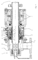
- the sealing head 1 shown in the drawing serves for supplying a heat transfer medium, in particular in Form of steam to a rotating pressure system 2, for example a drying drum, heating roller or the like, that in the drawing only with his Connection device is indicated.
- a rotating pressure system 2 for example a drying drum, heating roller or the like
- the sealing head 1 consists of a Pressure system 2 connected tubular rotor 3 and a roller bearing 4 arranged on the rotor 3 stationary sealing head housing 5.
- Das Sealing head housing 5 has at least one Connection piece 5 'for the heat transfer medium leading, not shown in the drawing Lead.
- the rotor 3 is above that of the heat transfer medium acted upon interior 8 of the sealing head housing 5 in open connection with the connecting piece 5 '. Thereby can the heat transfer medium through the Connection piece 5 'and the rotor 3 in that Get printing system 2.
- connection piece 5 'and Rolling bearings 4 Axially between the connection piece 5 'and Rolling bearings 4 is a rotor 3 against the wall of the Sealing head housing 5 sealing primary Sealing element 6 arranged axially in the direction to the rolling bearings 4 towards the atmosphere secondary seal 7 between the rotor 3 and the wall the sealing head housing 5 is connected downstream.
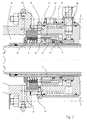
- the sealing head housing 5 is axially between the secondary seal 7 and the primary Sealing element 6 a ring around the rotor 3rd extending condensate chamber 9 arranged.
- the Condensate chamber 9 is above at least one, preferably via four overflow channels 10 with the Interior 8 in connection.
- the Condensate chamber 9 in heat-conducting contact with a Cooling system 11. This allows the vapor Heat transfer medium through the overflow channel 10 in the Enter the condensate chamber 9 and there under the influence of the cooling system 11 condense.
- the condensate that thus also in contact with the primary Sealing element 6 comes, prevents dry running this sealing element 6, so acts as Lubricant.
- the condensate chamber 9 in connection stands with the interior 8 of the sealing head housing 5, exist between the axially two sides of the primary Sealing element 6 no pressure differences, so that in any case there is no axial application of force.
- This allows the primary sealing element 6 as Ring lip seal to be formed, how how this also results from FIGS. 1 and 2, the Ring lip seal expediently from several ring lips arranged axially one behind the other is.
- the secondary seal 7 is, however, as usual Mechanical seal designed.
- the primary sealing element 6 is on its Interior 8 facing side from one Insulated washer 12, the heat flow from Interior 8 forth to the condensate chamber 9 prevented.
- the Sealing element 6 is in an annular fold Insulating washer 12 inserted.
- the rotor 3 is in the extending over the two seals 6, 7 Double-walled area.
- the condensate chamber 9 in a radially inner 14 'and outer 14 ", each axially extending flow channel divided.
- the inner and outer flow channels 14 ', 14 " are axially end-to-end in connection. This is basically one circulating flow possible.
- the sleeve part 13 is with radially outward, axially extending and arranged evenly distributed over the circumference Separators 13 'provided. These form between themselves the outer peripheral surface Flow channels 14 ".
- the cooling system 11 is of the condensate space 9 enclosing annular chamber 17 formed by Cooling water is flowing through.
- This annular chamber 17 is connected to the cooling water circuit, which the Counter ring cooling of the slide ring bearing 7 is used.
- This The annular chamber can, as in the drawing in FIG. 2 shown with itself towards the condensate chamber 9 extending ring grooves 18 may be provided, whereby the inner surface enlarged, thus a better Cooling effect is achieved.
- nipples 19 are therefore inserted only after final assembly of the sealing head 1 in the Way that only the topmost in the installed position Overflow channel 10 opened, the rest against are closed.
Landscapes
- Engineering & Computer Science (AREA)
- General Engineering & Computer Science (AREA)
- Mechanical Engineering (AREA)
- Mechanical Sealing (AREA)
- Turbine Rotor Nozzle Sealing (AREA)
- Drying Of Solid Materials (AREA)
- Rolls And Other Rotary Bodies (AREA)
Description
Die Erfindung betrifft einen Dichtkopf zum Transport eines Wärmeträgermediums in Form von Dampf zu einem rotierenden Drucksystem, wie einer Trockentrommel, Heizwalze oder dergleichen, und anschließendem Abführen des Kondensats, bestehend aus einem an das Drucksystem angeschlossenen rohrförmigen Rotor und einem über Wälzlager auf dem Rotor angeordneten stillstehenden Dichtkopfgehäuse mit mindestens einem Anschlußstutzen für eine das Wärmeträgermedium führende Anschlußleitung, wobei der Rotor über den vom Wärmeträgermedium beaufschlagten Innenraum des Dichtkopfgehäuses in offener Verbindung mit dem Anschlußstutzen steht und axial zwischen dem Anschlußstutzen und den Wälzlagern ein den Rotor gegen die Wand des Dichtkopfgehäuses abdichtendes primäres Dichtungselement angeordnet ist, dem axial in Richtung zu den Wälzlagern hin eine zur Atmosphäre dichtende, sekundäre Dichtung zwischen dem Rotor und der Wand des Dichtkopfgehäuses nachgeschaltet ist, und im Dichtkopfgehäuse axial zwischen der sekundären Dichtung und dem primären Dichtungselement ein sich ringförmig um den Rotor erstreckender Raum angeordnet ist.The invention relates to a sealing head for transport a heat transfer medium in the form of steam to one rotating printing system, like a drying drum, Heat roller or the like, and then Drainage of the condensate, consisting of one to the Tubular rotor and pressure system connected one arranged on the rotor via roller bearings stationary sealing head housing with at least one Connection piece for the heat transfer medium leading connecting line, the rotor over the from Heat transfer medium acted on the interior of the Sealing head housing in open connection with the Connection piece stands and axially between the Connection piece and the rolling bearings against the rotor primary wall sealing the sealing head housing Sealing element is arranged, the axially in the direction towards the rolling bearings a sealing to the atmosphere, secondary seal between the rotor and the wall of the Sealing head housing is connected downstream, and in Sealing head housing axially between the secondary Seal and the primary sealing element itself arranged in a ring around the rotor is.
Dichtköpfe dieser Art bei Verwendung von flüssigen Wärmeträgermedien sind aus der Praxis bekannt. Das Wärmeträgermedium sorgt dabei für eine Schmierung im Bereich des primären Dichtungselements, so daß trotz der üblicherweise hohen Drehzahlen des Drucksystems und der hohen Temperaturen des Wärmeträgermediums der Verschleiß gering gehalten und somit die Dichtfunktion des Dichtungselements möglichst wenig beeinträchtigt wird.Sealing heads of this type when using liquid Heat transfer media are known from practice. The Heat transfer medium ensures lubrication in the Area of the primary sealing element, so that despite the usually high speeds of the printing system and the high temperatures of the heat transfer medium Wear kept low and thus the sealing function the sealing element affected as little as possible becomes.
Kommt als Wärmeträgermedium jedoch Dampf zur Anwendung, so ist die angestrebte Schmierwirkung nicht mehr gegeben. Dies gilt insbesondere auch für den aus der US 1 953 525 A bekannten, gattungsgleichen Dichtkopf. Dort wird das sich im Drucksystem bildende Kondensat unmittelbar über ein Röhrensystem abgeführt. Die EP 0 448 730 A offenbart einen gattungsähnlichen Dichtkopf, bei dem ein zwischen zwei Dichtungen liegender Raum mit einem Vorlagemedium beaufschlagt ist, das außerhalb des Dichtkopfgehäuses im Umlauf geführt und gekühlt ist. Als Vorlagemedium kann das Wärmeträgermedium selbst verwendet werden, wozu der Raum in wärmeleitendem Kontakt mit einem Kühlsystem steht. However, steam is used as the heat transfer medium Application, the desired lubricating effect is not given more. This applies in particular to the of the US 1 953 525 A known, generic Sealing head. There is what is formed in the printing system Condensate drained off directly via a pipe system. EP 0 448 730 A discloses a generic one Sealing head, where one between two seals lying space with a template medium is circulating outside the seal head housing is led and cooled. This can be used as a template medium Heat transfer medium itself are used, which is why Space in thermal contact with a cooling system stands.
Der Erfindung liegt die Aufgabe zugrunde, einen Dichtkopf der eingangs genannten Art so auszubilden, daß auch bei der Verwendung von Dampf als Wärmeträgermedium eine hinreichende Schmierwirkung im Bereich des primären Dichtungselements sichergestellt ist.The invention has for its object a To design the sealing head of the type mentioned at the beginning that even when using steam as Heat transfer medium has a sufficient lubricating effect in the Ensured area of the primary sealing element is.
Diese Aufgabe wird nach der Erfindung dadurch gelöst, daß der Raum zwischen dem primären Dichtungselement und der sekundären Dichtung ein Kondensatraum ist, der in wärmeleitendem Kontakt mit einem Kühlsystem und der über wenigstens einen Überströmkanal mit dem vom Wärmeträgermedium beaufschlagten Innenraum in Verbindung steht.According to the invention, this object is achieved by that the space between the primary sealing element and the secondary seal is a condensate space that in heat-conducting contact with a cooling system and the via at least one overflow channel with that of Heat transfer medium charged inside Connection is established.
Der durch die Erfindung erreichte Vorteil besteht im wesentlichen darin, daß unmittelbar aus dem als Wärmeträgermedium dienenden Dampf ein Kondensat gebildet wird, das von der dem Innenraum des Dichtkopfgehäuses abgewandten Seite her auf das primäre Dichtungselement einwirkt. Durch die direkte Verbindung zwischen dem Innenraum und dem Kondensatraum wird ein Druckgleichgewicht eingestellt, wodurch auf das primäre Dichtungselement keine einseitigen Kraftbeanspruchungen durch unterschiedliche Druckbelastung einwirken. Auf diese Weise ist trotz der Verwendung von Dampf als Wärmeträgermedium eine ausreichende Schmierung des im übrigen besonders beanspruchten primären Dichtungselementes sichergestellt. The advantage achieved by the invention is essential in that directly from the as Steam used as a heat transfer medium is a condensate is formed by the the interior of the Sealing head housing facing away from that primary sealing element acts. By direct Connection between the interior and the A pressure equilibrium is set in the condensate chamber, whereby none on the primary sealing element one-sided force loads through act on different pressure loads. To this Way is despite the use of steam as Adequate lubrication of the heat transfer medium in the other particularly stressed primary Sealed element ensured.
In bevorzugter Ausführungsform sind das primäre Dichtungselement als Ringlippendichtung oder als Gleitringdichtung und die sekundäre Dichtung als Gleitringdichtung ausgebildet. Die Ringlippendichtung weist dabei zur Erhöhung der Dichtwirkung zweckmäßigerweise mehrere, axial hintereinander angeordnete Ringlippen auf.In a preferred embodiment, these are primary Sealing element as a ring lip seal or as Mechanical seal and the secondary seal as Mechanical seal designed. The ring lip seal points to increase the sealing effect expediently several, axially one behind the other arranged ring lips on.
Um einen unerwünschten Wärmetransport vom Innenraum des Dichtkopfgehäuses zum Kondensatraum hin zu verhindern, sieht die Erfindung vor, daß das primäre Dichtungselement auf seiner dem Innenraum zugewandten Seite von einer Isolierscheibe umschlossen ist. Das Dichtungselement ist dabei vorteilhafterweise in einen Ringfalz der Isolierscheibe eingelegt.To unwanted heat transfer from the interior of the sealing head housing to the condensate chamber prevent, the invention provides that the primary Sealing element on its interior facing Side is enclosed by an insulating washer. The Sealing element is advantageously in one Ring rebate of the insulating washer inserted.
Um weiter einen unerwünschten Wärmetransport vom Rotor zu den Dichtungen bzw. zum Kondensatraum zu unterbinden, ist der Rotor in zweckmäßiger Ausgestaltung der Erfindung in dem sich über die beiden Dichtungen erstreckenden Bereich doppelwandig ausgebildet.To further unwanted heat transfer from the rotor to the seals or the condensate chamber prevent, the rotor is more appropriate Embodiment of the invention in which the two seals extending area double-walled educated.
Um einerseits eine ausreichende Menge an Kondensat zum Dichtungselement hin zu befördern, andererseits eine hinreichende Kondensatbildung durch Abkühlung des Dampfes an der durch das Kühlsystem gekühlten Wand zu erreichen, ist vorgesehen, daß in dem Kondensatraum ein Hülsenteil angeordnet ist, das den Kondensatraum in einen radial inneren und äußeren, axial verlaufenden Strömungskanal unterteilt, wobei der innere und äußere Strömungskanal jeweils axial endseitig miteinander in Verbindung stehen.On the one hand, a sufficient amount of condensate for To convey sealing element, on the other hand sufficient condensate formation by cooling the Steam on the wall cooled by the cooling system achieve, it is provided that in the condensate chamber a sleeve part is arranged, the condensate space in a radially inner and outer, axially running flow channel divided, the inner and outer flow channels each axially are connected at the ends.
Das Hülsenteil kann dabei vorteilhafterweise mit radial auswärts gerichteten, axial verlaufenden und gleichmäßig über den Umfang verteilt angeordneten Trennstegen versehen sein, die zwischen sich die äußeren Strömungskanäle bilden.The sleeve part can advantageously with radially outward, axially extending and arranged evenly distributed over the circumference Separators are provided, which between them form outer flow channels.
Um eine ausreichende Strömung zu erzielen, sieht die Erfindung vor, daß innerhalb des Hülsenteils am Rotor fest angeordnete Förderorgane für das Kondensat umlaufen und einen Förderdruck für die Zirkulation des Kondensats in den Strömungskanälen erzeugen. Diese Förderorgane können in bevorzugter Ausführungsform der Erfindung von einem auf der Mantelfläche des die Gleitringdichtung tragenden Lagerings angeordneten Fördergewinde gebildet sein.In order to achieve a sufficient flow, the Invention before that within the sleeve part on the rotor fixed conveying devices for the condensate circulate and a delivery pressure for the circulation of the Generate condensate in the flow channels. This In a preferred embodiment, the conveying bodies can Invention of one on the lateral surface of the Mechanical bearing bearing ring arranged Conveying thread be formed.
Das Kühlsystem ist zweckmäßigerweise von einer den Kondensatraum umschließenden, von Kühlwasser durchströmten Ringkammer gebildet, die an den Kühlwasserkreislauf für die Gegenringkühlung des Gleitringlagers angeschlossen ist. Um einen besseren Wärmeübergang zu erzielen, ist die Ringkammer vorteilhafterweise mit in Richtung zum Kondensatraum sich erstreckenden Ringnuten versehen.The cooling system is conveniently one of the Condensate chamber enclosing cooling water flowed through annular chamber formed on the Cooling water circuit for the counter ring cooling of the Mechanical bearing is connected. For a better one Achieving heat transfer is the ring chamber advantageously with in the direction of the condensate chamber extending ring grooves.
Um schließlich ein Abfließen des Kondensats durch eine oder mehrere der in Einbaulage des Dichtkopfes unten angeordneten Überströmkanäle zu verhindern, empfiehlt es sich, daß die Überströmkanäle durch radial in das Dichtkopfgehäuse wahlweise einsetzbare Nippel zu öffnen oder absperrbar sind, wobei nur der in Einbaulage vertikal oberste Überströmkanal geöffnet ist.To finally drain the condensate through a or more of the sealing head installed below to prevent arranged overflow channels is recommended it that the overflow channels by radially in the Sealing head housing with optional nipples open or lockable, with only the in Installation position vertical top overflow channel opened is.
Im folgenden wird die Erfindung an einem in der Zeichnung dargestellten Ausführungsbeispiel näher erläutert; es zeigen:
- Fig. 1
- den Dichtkopf nach der Erfindung im Axialschnitt,
- Fig. 2
- eine nur teilweise Darstellung des Gegenstands nach Fig. 1,
- Fig. 3
- den Gegenstand nach Fig. 1 im Querschnitt,
- Fig. 4
- das Hülsenteil in Stirnansicht und
- Fig. 5
- das Hülsenteil im Querschnitt.
- Fig. 1
- the sealing head according to the invention in axial section,
- Fig. 2
- 1 shows only a partial representation of the object according to FIG. 1,
- Fig. 3
- 1 in cross section,
- Fig. 4
- the sleeve part in front view and
- Fig. 5
- the sleeve part in cross section.
Der in der Zeichnung dargestellte Dichtkopf 1 dient
zum Zuführen eines Wärmeträgermediums insbesondere in
Form von Dampf zu einem rotierenden Drucksystem 2,
beispielsweise einer Trockentrommel, Heizwalze oder
dergleichen, das in der Zeichnung nur mit seiner
Anschlußeinrichtung angedeutet ist.The sealing head 1 shown in the drawing serves
for supplying a heat transfer medium, in particular in
Form of steam to a rotating
Dazu besteht der Dichtkopf 1 aus einem an das
Drucksystem 2 angeschlossenen rohrförmigen Rotor 3 und
einem über Wälzlager 4 auf dem Rotor 3 angeordneten
stillstehenden Dichtkopfgehäuse 5. Das
Dichtkopfgehäuse 5 besitzt mindestens einen
Anschlußstutzen 5' für eine das Wärmeträgermedium
führende, in der Zeichnung nicht dargestellte
Anschlußleitung.For this purpose, the sealing head 1 consists of a
Der Rotor 3 steht über den vom Wärmeträgermedium
beaufschlagten Innenraum 8 des Dichtkopfgehäuses 5 in
offener Verbindung mit dem Anschlußstutzen 5'. Dadurch
kann das Wärmeträgermedium durch den
Anschlußstutzen 5' und den Rotor 3 in das
Drucksystem 2 gelangen.The
Axial zwischen dem Anschlußstutzen 5' und den
Wälzlagern 4 ist ein den Rotor 3 gegen die Wand des
Dichtkopfgehäuses 5 abdichtendes primäres
Dichtungselement 6 angeordnet, dem axial in Richtung
zu den Wälzlagern 4 hin atmosphärenseitig eine
sekundäre Dichtung 7 zwischen dem Rotor 3 und der Wand
des Dichtkopfgehäuses 5 nachgeschaltet ist.Axially between the connection piece 5 'and
Im Dichtkopfgehäuse 5 ist axial zwischen der
sekundären Dichtung 7 und dem primären
Dichtungselement 6 ein sich ringförmig um den Rotor 3
erstreckender Kondensatraum 9 angeordnet. Der
Kondensatraum 9 steht über wenigstens einen,
vorzugsweise über vier Überströmkanäle 10 mit dem
Innenraum 8 in Verbindung. Außerdem befindet sich der
Kondensatraum 9 in wärmeleitendem Kontakt mit einem
Kühlsystem 11. Hierdurch kann das dampfförmige
Wärmeträgermedium durch den Überströmkanal 10 in den
Kondensatraum 9 eintreten und dort unter dem Einfluß
des Kühlsystems 11 kondensieren. Das Kondensat, das
damit auch in Kontakt mit dem primären
Dichtungselement 6 kommt, verhindert ein Trockenlaufen
dieses Dichtungselementes 6, wirkt also als
Schmiermittel. Da der Kondensatraum 9 in Verbindung
mit dem Innenraum 8 des Dichtkopfgehäuses 5 steht,
bestehen zwischen den axial beiden Seiten des primären
Dichtungselementes 6 keine Druckunterschiede, so daß
jedenfalls keine axiale Kraftbeaufschlagung vorliegt.
Dadurch kann das primäre Dichtungselement 6 als
Ringlippendichtung ausgebildet sein, wobei, wie sich
dies auch aus den Fig. 1 und 2 ergibt, die
Ringlippendichtung zweckmäßigerweise aus mehreren,
axial hintereinander angeordneten Ringlippen aufgebaut
ist. Die sekundäre Dichtung 7 ist dagegen als übliche
Gleitringdichtung ausgebildet. In the sealing
Das primäre Dichtungselement 6 ist auf seiner dem
Innenraum 8 zugewandten Seite von einer
Isolierscheibe 12 umschlossen, die einen Wärmefluß vom
Innenraum 8 her zum Kondensatraum 9 verhindert. Das
Dichtungselement 6 ist dabei in einen Ringfalz der
Isolierscheibe 12 eingelegt.The
Um weiter einen Wärmefluß vom Innern des Rotors 3 her
zum Kondensatraum 9 zu mindern, ist der Rotor 3 in dem
sich über die beiden Dichtungen 6, 7 erstreckenden
Bereich doppelwandig ausgebildet.To further heat flow from the inside of the
In dem Kondensatraum 9 ist ein in den Fig. 4 und 5 im
einzelnen dargestelltes Hülsenteil 13 angeordnet, das
den Kondensatraum 9 in einen radial inneren 14' und
äußeren 14", jeweils axial verlaufenden Strömungskanal
unterteilt. Der innere und äußere Strömungskanal 14',
14" stehen dabei jeweils axial endseitig miteinander
in Verbindung. Dadurch ist grundsätzlich eine
umlaufende Strömung möglich. Das Hülsenteil 13 ist mit
radial auswärts gerichteten, axial verlaufenden und
gleichmäßig über den Umfang verteilt angeordneten
Trennstegen 13' versehen. Diese bilden zwischen sich
an der äußeren Umfangsfläche die äußeren
Strömungskanäle 14". Innerhalb des Hülsenteils 13 sind
am Rotor 3 fest angeordnete Förderorgane für das
Kondensat vorgesehen, die mit dem Rotor 3 umlaufen und
einen Förderdruck für die Zirkulation des Kondensats
in den Strömungskanälen 14', 14" erzeugen. Diese
Förderorgane sind von einem Fördergewinde gebildet,
das in der Fig. 1 in üblicher Darstellung lediglich
als Strich 15 angedeutet ist, wobei das Fördergewinde
auf der Mantelfläche des die Gleitringdichtung 7
tragenden Lagerings 16 angeordnet ist.4 and 5 in the
Das Kühlsystem 11 ist von einer den Kondensatraum 9
umschließenden Ringkammer 17 gebildet, die von
Kühlwasser durchströmt wird. Diese Ringkammer 17 ist
mit an den Kühlwasserkreislauf angeschlossen, der der
Gegenringkühlung des Gleitringlagers 7 dient. Diese
Ringkammer kann dabei, wie in der Zeichnung in Fig. 2
dargestellt, mit in Richtung zum Kondensatraum 9 sich
erstreckenden Ringnuten 18 versehen sein, wodurch die
innere Oberfläche vergrößert, somit eine bessere
Kühlwirkung erzielt wird.The
Um zu verhindern, daß das Kondensat durch einen der
unteren Überströmkanäle 10 zurück in den Innenraum 8
des Dichtkopfgehäuses 5 fließen kann, sind die
Überströmkanäle 10 durch radial in das
Dichtkopfgehäuse 5 wahlweise einsetzbare, entsprechend
unterschiedlich ausgebildete Nippel 19 zu öffnen oder
abzusperren. Das Einsetzen der Nippel 19 erfolgt daher
erst nach endgültiger Montage des Dichtkopfes 1 in der
Weise, daß nur der in Einbaulage vertikal oberste
Überströmkanal 10 geöffnet, die übrigen dagegen
geschlossen sind.To prevent the condensate from passing through one of the
Claims (13)
- Sealing head for conveying a heat transfer medium in the form of steam to a rotating pressure system (2) such as a drying drum, heating roll or the like, subsequently carrying away the condensate, comprising a tubular rotor (3) linked to the pressure system (2) and a stationary sealing head casing (5) arranged on the rotor (3) via rolling bearings (4), with at least one connection fitting (5') for a connecting pipe to carry the heat transfer medium, the rotor (3) communicating openly with the connection fitting (5') via the interior (8) of the sealing head's casing (5) (said interior (8) being acted upon by the heat transfer medium), and disposed axially between the connection fitting (5') and the rolling bearings (4) is a primary sealing element (6) which seals the rotor (3) with respect to the wall of the sealing head's casing (5), arranged axially downstream of which in the direction of the rolling bearings (4), and between the rotor (3) and the wall of the sealing head's casing (5), is a secondary seal (7) for sealing it off from the atmosphere, and arranged in the sealing head's casing (5), axially between the secondary seal (7) and the primary sealing element (6), is a compartment extending annularly around the rotor (3), characterised in that the compartment between the primary sealing element (6) and the secondary seal (7) is a condensate compartment (9) which is in thermally conductive contact with a cooling system (11) and which communicates via at least one overflow channel (10) with the interior (8) charged with the heat transfer medium.
- Sealing head according to claim 1, characterised in that the primary sealing element (6) is configured as an annular lip seal or rotating mechanical seal and the secondary seal (7) as a rotating mechanical seal.
- Sealing head according to claim 2, characterised in that the annular lip seal features a plurality of annular lips arranged axially one behind the other.
- Sealing head according to any of claims 1 to 3, characterised in that on its side facing the interior (8) the primary sealing element (6) is surrounded by an insulating panel (12).
- Sealing element according to claim 4, characterised in that the sealing element (6) is inserted into an annular rebate in the insulating panel (12).
- Sealing element according to any of claims 1 to 5, characterised in that the rotor (3) is a double-walled construction in the area extending past the two seals (6, 7).
- Sealing head according to any of claims 1 to 6, characterised in that arranged in the condensate compartment (9) is a sleeve member (13) which divides the condensate compartment (9) into a radially inner (14') and outer (14") axially extending flow channel, with the inner and outer flow channels (14', 14") in each case communicating axially with each other at the ends.
- Sealing head according to claim 7, characterised in that the sleeve member (13) is provided with radially outward-facing, axially extending partitioning lands (13') which are spaced evenly around the circumference and which between them form the outer flow channels (14").
- Sealing head according to claim 7 or 8, characterised in that fixedly arranged transfer units for the condensate circulate on the rotor (3) within the sleeve member (13) and generate a conveying pressure for circulation of the condensate in the flow channels (14', 14").
- Sealing head according to claim 9, characterised in that the conveyor units are constituted by a conveying thread (15) arranged on the generating surface of the bearing ring (16) carrying the rotating mechanical seal (7).
- Sealing head according to any of claims 1 to 10, characterised in that the cooling system (11) is formed by an annular chamber (17) which surrounds the condensate compartment (9) and through which cooling water flows, which is connected up to the coolant circuit for cooling the mating ring of the rotating mechanical seal (7).
- Sealing head according to claim 11, characterised in that the annular chamber (17) is provided with annular slots (18) which extend towards the condensate compartment (9).
- Sealing head according to any of claims 1 to 12, characterised in that the overflow channels (10) are are adapted to be opened or closed by nipples (19) which can be inserted into the sealing head's casing (5) as needed, with only the overflow channel (10) that is vertically uppermost in the installed position being open.
Applications Claiming Priority (2)
| Application Number | Priority Date | Filing Date | Title |
|---|---|---|---|
| DE19618661 | 1996-05-09 | ||
| DE19618661A DE19618661C1 (en) | 1996-05-09 | 1996-05-09 | Sealing head for transporting a heat transfer medium to a rotating printing system |
Publications (2)
| Publication Number | Publication Date |
|---|---|
| EP0806578A1 EP0806578A1 (en) | 1997-11-12 |
| EP0806578B1 true EP0806578B1 (en) | 2003-09-24 |
Family
ID=7793823
Family Applications (1)
| Application Number | Title | Priority Date | Filing Date |
|---|---|---|---|
| EP97104456A Expired - Lifetime EP0806578B1 (en) | 1996-05-09 | 1997-03-15 | Sealing head for the transport of a heat carrier to a rotating pressure system |
Country Status (4)
| Country | Link |
|---|---|
| US (1) | US5778971A (en) |
| EP (1) | EP0806578B1 (en) |
| DE (1) | DE19618661C1 (en) |
| ES (1) | ES2202505T3 (en) |
Families Citing this family (17)
| Publication number | Priority date | Publication date | Assignee | Title |
|---|---|---|---|---|
| DE19707876C2 (en) * | 1997-02-27 | 2002-09-26 | Voith Paper Patent Gmbh | roll arrangement |
| DE19747555A1 (en) * | 1997-10-28 | 1999-04-29 | Voith Sulzer Papiertech Patent | Heated and / or coolable cylinder |
| SE515396C2 (en) * | 1999-05-12 | 2001-07-30 | Abb Ab | A swivel for flexible transport of a fluid |
| US6164316A (en) * | 1999-12-23 | 2000-12-26 | Deublin Company | High temperature rotating union |
| TW427449U (en) * | 2000-01-28 | 2001-03-21 | Ind Tech Res Inst | Cooling device for hollow screw |
| DE10205790A1 (en) * | 2002-02-13 | 2003-08-28 | Maier Christian Masch | Sealing head for supplying a heat transfer medium |
| NO20022196L (en) * | 2002-05-08 | 2009-11-16 | Advanced Prod & Loading As | Device for interconnecting pipelines which conduct fluid under pressure |
| US20040163709A1 (en) * | 2003-02-24 | 2004-08-26 | Baugh Benton F. | Fluid swivel with cooling porting |
| ITUD20030167A1 (en) * | 2003-08-08 | 2005-02-09 | De Longhi Spa | COAXIAL COUPLING JOINT. |
| CN100387368C (en) * | 2005-11-17 | 2008-05-14 | 王溥岚 | water circulation exchanger |
| US8172738B2 (en) * | 2006-01-18 | 2012-05-08 | 3M Innovative Properties Company | Dead-shaft roller with aerostatic rotary union |
| ITPR20060062A1 (en) * | 2006-07-03 | 2008-01-04 | Cft Spa | SYSTEM FOR CREATING A STERILE BARRIER AND LUBRICATING AND REFRIGERATING MOBILE PARTS IN UHT STERILIZATION PLANTS. |
| CN102410415A (en) * | 2011-08-25 | 2012-04-11 | 江苏腾旋科技股份有限公司 | High-temperature high-speed rotary joint |
| US10947992B2 (en) * | 2015-08-17 | 2021-03-16 | Pedro Arnulfo Sarmiento | Convectors |
| DE102019218288A1 (en) * | 2019-11-26 | 2021-05-27 | Christian Maier GmbH & Co. KG, Maschinenfabrik | Rotating union |
| US11953126B1 (en) * | 2023-04-21 | 2024-04-09 | Princetel, Inc. | Fluid rotary joint assembly suitable for high rotational speed |
| US20250305607A1 (en) * | 2024-04-02 | 2025-10-02 | Kadant Johnson Llc | Rotary Joint with Adjustable Syphon for Rotating Cylinder |
Citations (1)
| Publication number | Priority date | Publication date | Assignee | Title |
|---|---|---|---|---|
| US1953525A (en) * | 1931-06-13 | 1934-04-03 | Young George Harold | Siphon exhaust for drier rolls |
Family Cites Families (8)
| Publication number | Priority date | Publication date | Assignee | Title |
|---|---|---|---|---|
| US2331615A (en) * | 1942-06-22 | 1943-10-12 | Rotary Seal Company | Sealed coupling |
| US3638606A (en) * | 1969-11-21 | 1972-02-01 | Gen Electric | Apparatus for controlling the coating of selected surfaces of an article of manufacture |
| US3704669A (en) * | 1970-07-15 | 1972-12-05 | Stevens Corp | Vibrating roller with means for circulating a cooling fluid for use in bearing and drive gear lubrication |
| US4230928A (en) * | 1978-12-18 | 1980-10-28 | Wolff Manufacturing Company | Method and machine for rebuilding track roller assemblies |
| DE3417093A1 (en) * | 1984-05-09 | 1985-11-14 | Küsters, Eduard, 4150 Krefeld | ROTATING CONNECTION HEAD FOR HEATABLE OR COOLABLE ROLLERS |
| DE3812533A1 (en) * | 1988-04-15 | 1989-10-26 | Josef Seelen | SEAL FOR BLOW TUBE OR SHAFT |
| US4965920A (en) * | 1989-07-07 | 1990-10-30 | Phillips Petroleum Company | Fluid heated roll apparatus and method |
| ES2035665T3 (en) * | 1990-02-23 | 1993-04-16 | Christian Maier Gmbh & Co. Maschinenfabrik | SEALING HEAD FOR THE SUPPLY OF A HEAT CARRYING MEDIA TO A ROTATING PRESSURE SYSTEM. |
-
1996
- 1996-05-09 DE DE19618661A patent/DE19618661C1/en not_active Expired - Lifetime
-
1997
- 1997-03-15 EP EP97104456A patent/EP0806578B1/en not_active Expired - Lifetime
- 1997-03-15 ES ES97104456T patent/ES2202505T3/en not_active Expired - Lifetime
- 1997-05-09 US US08/853,644 patent/US5778971A/en not_active Expired - Lifetime
Patent Citations (1)
| Publication number | Priority date | Publication date | Assignee | Title |
|---|---|---|---|---|
| US1953525A (en) * | 1931-06-13 | 1934-04-03 | Young George Harold | Siphon exhaust for drier rolls |
Also Published As
| Publication number | Publication date |
|---|---|
| EP0806578A1 (en) | 1997-11-12 |
| ES2202505T3 (en) | 2004-04-01 |
| US5778971A (en) | 1998-07-14 |
| DE19618661C1 (en) | 1997-10-09 |
Similar Documents
| Publication | Publication Date | Title |
|---|---|---|
| EP0806578B1 (en) | Sealing head for the transport of a heat carrier to a rotating pressure system | |
| EP0340503B1 (en) | Heated roll | |
| DE19613609C2 (en) | Axial piston machine with internal flushing circuit | |
| DE2037387A1 (en) | Bearing arrangement with flexible labyrinth seals | |
| DE29704386U1 (en) | Four-row tapered roller bearing, especially for work rolls on roll stands | |
| CH651899A5 (en) | DRIVE WITH A MOTOR AND A TENSION SHAFT TRANSMISSION. | |
| DE1475601A1 (en) | Mechanical compression seal | |
| DE3127122C2 (en) | Liquid-cooled valve seat for an exhaust valve of a reciprocating internal combustion engine | |
| DE9103935U1 (en) | Bearing housing for a multi-row rolling bearing or for several coaxially arranged rolling bearings | |
| DE3140425A1 (en) | DEVICE FOR PRODUCING AND / OR PROCESSING RAILWAY MATERIAL | |
| EP0448730B1 (en) | Sealed head for the transfer of a heat transfer medium to a rotary presssure system | |
| DE1260249B (en) | Stuffing box for sealing against gaseous media | |
| DE102008046890B4 (en) | Rotary feedthrough with axial sliding seal device | |
| DE2201006C3 (en) | Cooled wire drawing drum | |
| EP3595954A1 (en) | Transmission, in particular for the powertrain of rail vehicles | |
| EP0220558A2 (en) | Fluid distributor for a rotating clamping cylinder | |
| DE2351494A1 (en) | HYDROSTATIC WHEEL BEARING | |
| EP1336807B1 (en) | Sealed head for the transfer of a heat transfer medium | |
| DE102021208704A1 (en) | Housing cover and planetary gear | |
| DE3115193C2 (en) | Radial roller bearings with oil bath lubrication | |
| DE69002759T3 (en) | LUBRICATION FOR DEFLECTION ADJUSTING ROLLER. | |
| DE2817878B1 (en) | Oil roller | |
| DE102010017620B4 (en) | Sealing arrangement and roller | |
| DE2433468C3 (en) | Cooling water pump that can be attached to an internal combustion engine housing | |
| DE19507868B4 (en) | Scherbeneisautomat |
Legal Events
| Date | Code | Title | Description |
|---|---|---|---|
| PUAI | Public reference made under article 153(3) epc to a published international application that has entered the european phase |
Free format text: ORIGINAL CODE: 0009012 |
|
| 17P | Request for examination filed |
Effective date: 19970910 |
|
| AK | Designated contracting states |
Kind code of ref document: A1 Designated state(s): ES FI FR GB IT NL |
|
| RBV | Designated contracting states (corrected) |
Designated state(s): ES FI FR GB IT NL |
|
| REG | Reference to a national code |
Ref country code: DE Ref legal event code: 8566 |
|
| 17Q | First examination report despatched |
Effective date: 20000306 |
|
| RIC1 | Information provided on ipc code assigned before grant |
Ipc: 7F 16L 27/08 B Ipc: 7F 16C 13/00 A |
|
| GRAH | Despatch of communication of intention to grant a patent |
Free format text: ORIGINAL CODE: EPIDOS IGRA |
|
| GRAS | Grant fee paid |
Free format text: ORIGINAL CODE: EPIDOSNIGR3 |
|
| GRAA | (expected) grant |
Free format text: ORIGINAL CODE: 0009210 |
|
| AK | Designated contracting states |
Kind code of ref document: B1 Designated state(s): ES FI FR GB IT NL |
|
| REG | Reference to a national code |
Ref country code: GB Ref legal event code: FG4D Free format text: NOT ENGLISH |
|
| GBT | Gb: translation of ep patent filed (gb section 77(6)(a)/1977) | ||
| REG | Reference to a national code |
Ref country code: ES Ref legal event code: FG2A Ref document number: 2202505 Country of ref document: ES Kind code of ref document: T3 |
|
| ET | Fr: translation filed | ||
| PLBE | No opposition filed within time limit |
Free format text: ORIGINAL CODE: 0009261 |
|
| STAA | Information on the status of an ep patent application or granted ep patent |
Free format text: STATUS: NO OPPOSITION FILED WITHIN TIME LIMIT |
|
| 26N | No opposition filed |
Effective date: 20040625 |
|
| REG | Reference to a national code |
Ref country code: FR Ref legal event code: PLFP Year of fee payment: 20 |
|
| PGFP | Annual fee paid to national office [announced via postgrant information from national office to epo] |
Ref country code: FR Payment date: 20151209 Year of fee payment: 20 |
|
| PGFP | Annual fee paid to national office [announced via postgrant information from national office to epo] |
Ref country code: NL Payment date: 20160324 Year of fee payment: 20 Ref country code: ES Payment date: 20160125 Year of fee payment: 20 |
|
| PGFP | Annual fee paid to national office [announced via postgrant information from national office to epo] |
Ref country code: GB Payment date: 20160322 Year of fee payment: 20 Ref country code: FI Payment date: 20160316 Year of fee payment: 20 |
|
| PGFP | Annual fee paid to national office [announced via postgrant information from national office to epo] |
Ref country code: IT Payment date: 20160330 Year of fee payment: 20 |
|
| REG | Reference to a national code |
Ref country code: NL Ref legal event code: MK Effective date: 20170314 |
|
| REG | Reference to a national code |
Ref country code: GB Ref legal event code: PE20 Expiry date: 20170314 |
|
| PG25 | Lapsed in a contracting state [announced via postgrant information from national office to epo] |
Ref country code: GB Free format text: LAPSE BECAUSE OF EXPIRATION OF PROTECTION Effective date: 20170314 |
|
| REG | Reference to a national code |
Ref country code: ES Ref legal event code: FD2A Effective date: 20180508 |
|
| PG25 | Lapsed in a contracting state [announced via postgrant information from national office to epo] |
Ref country code: ES Free format text: LAPSE BECAUSE OF EXPIRATION OF PROTECTION Effective date: 20170316 |