EP1336807B1 - Sealed head for the transfer of a heat transfer medium - Google Patents
Sealed head for the transfer of a heat transfer medium Download PDFInfo
- Publication number
- EP1336807B1 EP1336807B1 EP03000491A EP03000491A EP1336807B1 EP 1336807 B1 EP1336807 B1 EP 1336807B1 EP 03000491 A EP03000491 A EP 03000491A EP 03000491 A EP03000491 A EP 03000491A EP 1336807 B1 EP1336807 B1 EP 1336807B1
- Authority
- EP
- European Patent Office
- Prior art keywords
- sealing head
- rotor
- sealing
- cooling
- ring seal
- Prior art date
- Legal status (The legal status is an assumption and is not a legal conclusion. Google has not performed a legal analysis and makes no representation as to the accuracy of the status listed.)
- Expired - Lifetime
Links
Images

Classifications
-
- F—MECHANICAL ENGINEERING; LIGHTING; HEATING; WEAPONS; BLASTING
- F26—DRYING
- F26B—DRYING SOLID MATERIALS OR OBJECTS BY REMOVING LIQUID THEREFROM
- F26B13/00—Machines and apparatus for drying fabrics, fibres, yarns, or other materials in long lengths, with progressive movement
- F26B13/10—Arrangements for feeding, heating or supporting materials; Controlling movement, tension or position of materials
- F26B13/14—Rollers, drums, cylinders; Arrangement of drives, supports, bearings, cleaning
- F26B13/18—Rollers, drums, cylinders; Arrangement of drives, supports, bearings, cleaning heated or cooled, e.g. from inside, the material being dried on the outside surface by conduction
- F26B13/183—Arrangements for heating, cooling, condensate removal
Definitions
- the invention relates to a sealing head for supplying a heat transfer medium, esp. A heat transfer oil, to a rotating pressure system, such as a drying drum, heat roller or the like.
- a sealing head for supplying a heat transfer medium, esp. A heat transfer oil
- a rotating pressure system such as a drying drum, heat roller or the like.
- Such a sealing head is known, for example, from EP 0 448 730 and has proven extremely successful in practice (see also document DE-C-196 18 661). It should be noted, however, that this solution requires increased expense because of the circulation of a master medium.
- the invention has for its object to improve by constructive development of a sealing head of the type mentioned so that in a simplified structure nevertheless operation at maximum temperature of the heat transfer medium is made possible without increased wear occurs especially in the sealing area.
- the mechanical seal is surrounded by a sealing head housing arranged on the cooling flange, which extends axially on both sides of the mechanical seal, and that on the connecting piece facing side of the mechanical seal a space between the rotor and the sealing head housing up on a remaining narrow annular gap sealing insulating is provided.
- the advantage achieved by the invention consists essentially in the fact that despite reduced expenses, such as the implementation of simple cooling measures and the attachment of a simple insulating safe operation at maximum temperature of the heat transfer medium is possible without standstill problems occur at the seal.
- the insulating element is expediently designed as a sealing head housing fixed sleeve part, wherein the connecting piece facing side is formed as a radially projecting inner flange, whose lateral surface forms the boundary of the annular gap as a boundary to the engine. In this way, a clear thermal insulation is first achieved to the connection piece out.
- the insulating member is supported axially against the cooling flange, since thus a seamless insulation is achieved to the cooling flange.
- the insulating element consists of a material of low thermal conductivity.
- the cooling flange has an annular cooling chamber for a flowing cooling medium.
- the cooling chamber is provided with a respective diametrically arranged inlet and outlet. This ensures a complete separation of this cooling circuit, so that the cooling can be done either with lubricating oil or only with cooling water.
- a closed chamber forming sealing element is arranged, wherein in the chamber a filling nozzle for a preferably liquid medium opens.
- This chamber can be filled with a suitable liquid without pressure via the filling nozzle, whereby a chemical reaction between the oxygen in the air and over the mechanical seal leaking oil leakage is prevented.
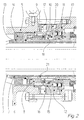
- the sealing head 1 shown in the drawing is used for supplying a heat transfer medium, in particular a heat transfer oil, to a rotating printing system 2, for example a drying drum, heat roller or the like, which is indicated in the drawing only with its connecting device.
- the sealing head 1 consists of a connected to the pressure system 2 tubular rotor 3 and a two roller bearings 4 arranged on the rotor 3 stationary sealing head housing 5, which has a connection piece 6 for a heat transfer medium leading, not shown in the drawing connection line.
- the rotor 3 is at the open end of the tube via openings 7 in direct communication with the Connecting piece 6, so that the heat transfer medium can pass through the connecting piece 6 and the rotor 3 in the printing system.
- a mechanical seal 8 is arranged, which seals the rotor 3 against the wall of the sealing head housing 5.
- This mechanical seal 8 is preferably made of a sealing ring 10 secured to the rotor 3 via a bellows 9 and a sealing ring 11 fixedly arranged on the sealing head housing 5.
- the mechanical seal 8 is enclosed by a cooling flange 12 arranged on the sealing head housing 5, which extends axially on both sides to the mechanical seal 8.
- the insulating member 14 is designed in detail as fixed to the sealing head housing 5 sleeve part, wherein the connecting piece 6 facing side is formed as a radially projecting inner flange.
- the inner circumferential surface of this inner flange forms the boundary of the annular gap 13 towards the rotor 3.
- the axial height of this inner flange affects the width of the annular gap 13, whereby the circulation of heat transfer medium between the outer region of the mechanical seal 8 and the area flowed through at the connecting piece 6 and the openings 7 largely prevented and thus the temperature of the Heat transfer medium in the sealing area is significantly reduced.
- the insulating member 14 is supported axially against the cooling flange 12, so that, since the insulating member 14 is suitably made of a material of low thermal conductivity, a continuous heat-insulating effect is achieved up to the cooling flange 12.
- the cooling flange 12 has, as can be seen in particular from Figure 2, an annular cooling chamber 15, which is flowed through by a cooling medium.
- the cooling chamber 15 is provided with a respective diametrically arranged inlet and outlet 16,17.
- a cooling medium a variety of suitable liquids can be used, since this cooling circuit is self-contained, so no contact can occur, for example, with the heat transfer medium.
- lubricating oil or even simple cooling water will be used for this purpose.
- a closed chamber 18 forming sealing element 19 is disposed between the sealing head housing 5 and the rotor 3.
- This thus formed chamber 18 can be filled via a filling nozzle 20 with a preferably liquid medium, thereby preventing that a chemical reaction of reaching over the mechanical seal 8 in this chamber 18 oil leakage can occur with atmospheric oxygen.
- the rotor 3 is in the over the mechanical seal 8 and the sealing member 19 and the bearing 4 extending, provided with the reference numeral 21 area formed double-walled, which in addition the heat transfer from the rotor 3 ago to the mechanical seal 8 is reduced.
Abstract
Description
Die Erfindung betrifft einen Dichtkopf zum Zuführen eines Wärmeträgermediums, insbes. eines Wärmeträgeröls, zu einem rotierenden Drucksystem, wie einer Trockentrommel, Heizwalze oder dergl., bestehend aus einem an das Drucksystem angeschlossenen rohrförmigen Rotor und einem über mittels Fett oder Öl geschmierten Wälzlager auf dem Rotor angeordneten stillstehenden Dichtkopfgehäuse mit mindestens einem Anschlußstutzen für eine das Wärmeträgermedium führende Anschlußleitung, wobei im Inneren des Dichtkopfgehäuses der Rotor in offener Verbindung mit dem Anschlußstutzen steht und axial zwischen dem Anschlußstutzen und den Wälzlagern eine den Rotor gegen die Wand des Dichtkopfgehäuses abdichtende Gleitringdichtung angeordnet ist.The invention relates to a sealing head for supplying a heat transfer medium, esp. A heat transfer oil, to a rotating pressure system, such as a drying drum, heat roller or the like. Comprising a connected to the pressure system tubular rotor and lubricated by means of grease or oil bearings on the rotor arranged stationary sealing head housing with at least one connecting piece for a heat transfer medium leading connecting line, wherein in the interior of the sealing head housing the rotor is in open communication with the connecting piece and axially between the connecting piece and the rolling bearings a rotor against the wall of the sealing head housing sealing mechanical seal is arranged.
Ein derartiger Dichtkopf ist beispielsweise aus der EP 0 448 730 bekannt und hat sich in der Praxis außerordentlich bewährt (siehe auch Dokument DE-C-196 18 661). Zu beachten ist jedoch, daß diese Lösung einen erhöhten Aufwand wegen der Zirkulation eines Vorlagemediums erfordert.Such a sealing head is known, for example, from EP 0 448 730 and has proven extremely successful in practice (see also document DE-C-196 18 661). It should be noted, however, that this solution requires increased expense because of the circulation of a master medium.
Der Erfindung liegt die Aufgabe zugrunde, durch konstruktive Weiterentwicklung einen Dichtkopf der eingangs genannten Art so zu verbessern, daß bei vereinfachtem Aufbau gleichwohl ein Betrieb bei Maximaltemperatur des Wärmeträgermediums ermöglicht wird, ohne daß ein erhöhter Verschleiß insbesondere im Dichtungsbereich auftritt.The invention has for its object to improve by constructive development of a sealing head of the type mentioned so that in a simplified structure nevertheless operation at maximum temperature of the heat transfer medium is made possible without increased wear occurs especially in the sealing area.
Diese Aufgabe wird nach der Erfindung dadurch gelöst, daß die Gleitringdichtung von einem am Dichtkopfgehäuse angeordneten Kühlflansch umschlossen ist, der sich axial beidseits zur Gleitringdichtung erstreckt, und daß an der dem Anschlußstutzen zugewandten Seite der Gleitringdichtung ein den Raum zwischen dem Rotor und dem Dichtkopfgehäuse bis auf einen verbleibenden schmalen Ringspalt abdichtendes Isolierelement vorgesehen ist.This object is achieved according to the invention in that the mechanical seal is surrounded by a sealing head housing arranged on the cooling flange, which extends axially on both sides of the mechanical seal, and that on the connecting piece facing side of the mechanical seal a space between the rotor and the sealing head housing up on a remaining narrow annular gap sealing insulating is provided.
Der durch die Erfindung erreichte Vorteil besteht im wesentlichen darin, daß trotz reduzierter Aufwendungen, wie die Durchführung von einfachen Kühlmaßnahmen sowie die Anbringung eines einfachen Isolierelementes ein sicherer Betrieb bei Maximaltemperatur des Wärmeträgermediums möglich wird, ohne daß Standzeitprobleme an der Dichtung auftreten.The advantage achieved by the invention consists essentially in the fact that despite reduced expenses, such as the implementation of simple cooling measures and the attachment of a simple insulating safe operation at maximum temperature of the heat transfer medium is possible without standstill problems occur at the seal.
In bevorzugter Ausführungsform der Erfindung ist das Isolierelement zweckmäßigerweise als am Dichtkopfgehäuse festgelegtes Hülsenteil gestaltet, wobei die dem Anschlußstutzen zugewandte Seite als radial vorstehender Innenflansch ausgebildet ist, dessen Mantelfläche die Begrenzung des Ringspaltes als Begrenzung zum Motor hin bildet. Auf diese Weise wird zunächst eine deutliche Wärmeisolierung zum Anschlußstutzen hin erreicht.In a preferred embodiment of the invention, the insulating element is expediently designed as a sealing head housing fixed sleeve part, wherein the connecting piece facing side is formed as a radially projecting inner flange, whose lateral surface forms the boundary of the annular gap as a boundary to the engine. In this way, a clear thermal insulation is first achieved to the connection piece out.
Dabei ist es weiter von Vorteil, wenn sich das Isolierelement axial gegen den Kühlflansch abstützt, da somit eine nahtlose Isolierung bis zum Kühlflansch hin erreicht wird. Dazu ist im Rahmen der Erfindung zweckmäßigerweise vorzusehen, daß das Isolierelement aus einem Material von geringer Wärmeleitfähigkeit besteht.It is further advantageous if the insulating member is supported axially against the cooling flange, since thus a seamless insulation is achieved to the cooling flange. For this purpose, it is expedient to provide in the context of the invention that the insulating element consists of a material of low thermal conductivity.
Eine weitere Verminderung der Temperatur im Bereich der Gleitringdichtung wird dadurch erreicht, daß der Kühlflansch eine ringförmige Kühlkammer für ein durchströmendes Kühlmedium aufweist. Hierzu empfiehlt es sich weiter, daß die Kühlkammer mit je einem diametral zueinander angeordneten Zu- bzw. Ablauf versehen ist. Dadurch ist eine vollständige Trennung dieses Kühlkreislaufes gewährleistet, so daß die Kühlung wahlweise mit Schmieröl oder auch lediglich mit Kühlwasser erfolgen kann.A further reduction of the temperature in the region of the mechanical seal is achieved in that the cooling flange has an annular cooling chamber for a flowing cooling medium. For this purpose, it is further recommended that the cooling chamber is provided with a respective diametrically arranged inlet and outlet. This ensures a complete separation of this cooling circuit, so that the cooling can be done either with lubricating oil or only with cooling water.
Darüber hinaus wird im Rahmen der Erfindung vorgeschlagen, daß auf der dem Anschlußstutzen abgewandten Seite der Gleitringdichtung zwischen dem Dichtkopfgehäuse und dem Rotor ein eine geschlossene Kammer bildendes Dichtelement angeordnet ist, wobei in die Kammer ein Befüllstutzen für ein vorzugsweise flüssiges Medium mündet. Diese Kammer kann mit einer geeigneten Flüssigkeit ohne Druck über den Befüllstutzen befüllt werden, wodurch eine chemische Reaktion zwischen dem Luftsauerstoff und der über die Gleitringdichtung übertretenden Ölleckage verhindert wird.In addition, it is proposed in the invention that on the side facing away from the connecting piece side of the mechanical seal between the sealing head housing and the rotor a closed chamber forming sealing element is arranged, wherein in the chamber a filling nozzle for a preferably liquid medium opens. This chamber can be filled with a suitable liquid without pressure via the filling nozzle, whereby a chemical reaction between the oxygen in the air and over the mechanical seal leaking oil leakage is prevented.
Schließlich besteht noch in an sich bekannter Weise die Möglichkeit, eine zusätzliche Isolierung zum Innenraum des Rotors hin in der Weise vorzunehmen, daß der Rotor in dem sich über die Gleitringdichtung bzw. das Dichtungselement und die Lager erstreckenden Bereich doppelwandig ausgebildet ist.Finally, in a manner known per se, it is possible to provide additional insulation to the interior of the rotor in such a way that the rotor is designed to be double-walled in the region extending over the mechanical seal or the sealing element and the bearings.
Im folgenden wird die Erfindung an einem Ausführungsbeispiel näher erläutert; es zeigen:
- Fig. 1
- den Dichtkopf im Querschnitt dargestellt,
- Fig. 2
- eine Detailansicht des Gegenstandes nach Figur 1.
- Fig. 1
- the sealing head shown in cross section,
- Fig. 2
- a detailed view of the article of Figure 1.
Der in der Zeichnung dargestellte Dichtkopf 1 dient zum Zuführen eines Wärmeträgermediums, insbesondere eines Wärmeträgeröls, zu einem rotierenden Drucksystem 2, beispielsweise einer Trockentrommel, Heizwalze oder dergleichen, das in der Zeichnung nur mit seiner Anschlußeinrichtung angedeutet ist. Dazu besteht der Dichtkopf 1 aus einem an das Drucksystem 2 angeschlossenen rohrförmigen Rotor 3 und einem über zwei Wälzlager 4 auf dem Rotor 3 angeordneten stillstehenden Dichtkopfgehäuse 5, das einen Anschlußstutzen 6 für eine das Wärmeträgermedium führende, in der Zeichnung nicht näher dargestellte Anschlußleitung besitzt. Im Inneren des Dichtkopfgehäuses 5 steht der Rotor 3 am offenen Rohrende über Öffnungen 7 in unmittelbarer Verbindung mit dem Anschlußstutzen 6, so daß das Wärmeträgermedium durch den Anschlußstutzen 6 und den Rotor 3 in das Drucksystem gelangen kann. Axial zwischen dem Anschlußstutzen 6 und den Wälzlagern 4 ist eine Gleitringdichtung 8 angeordnet, die den Rotor 3 gegen die Wand des Dichtkopfgehäuses 5 abdichtet. Diese Gleitringdichtung 8 besteht vorzugsweise aus einem über einen Faltenbalg 9 am Rotor 3 befestigten Dichtungsring 10 und einem am Dichtkopfgehäuse 5 feststehend angeordneten Dichtungsring 11.The sealing head 1 shown in the drawing is used for supplying a heat transfer medium, in particular a heat transfer oil, to a rotating
Die Gleitringdichtung 8 ist von einem am Dichtkopfgehäuse 5 angeordneten Kühlflansch 12 umschlossen, der sich axial beidseits zur Gleitringdichtung 8 erstreckt.The
Ferner ist an der dem Anschlußstutzen 6 zugewandten Seite der Gleitringdichtung 8 ein den Raum zwischen dem Rotor 3 und dem Dichtkopfgehäuse 5 bis auf einen verbleibenden schmalen Ringspalt 13 abdichtendes Isolierelement 14 vorgesehen.Further, at the connecting
Das Isolierelement 14 ist im einzelnen als am Dichtkopfgehäuse 5 festgelegtes Hülsenteil gestaltet, wobei die dem Anschlußstutzen 6 zugewandte Seite als radial vorstehender Innenflansch ausgebildet ist. Die innere Mantelfläche dieses Innenflansches bildet die Begrenzung des Ringspaltes 13 zum Rotor 3 hin. Die axiale Höhe dieses Innenflansches beeinflußt dabei die Breite des Ringspaltes 13, wodurch die Zirkulation von Wärmeträgermedium zwischen dem äußeren Bereich der Gleitringdichtung 8 und dem durchströmten Bereich am Anschlußstutzen 6 und den Öffnungen 7 weitgehend unterbunden und somit die Temperatur des Wärmeträgermediums im Dichtungsbereich deutlich reduziert wird. Im übrigen stützt sich das Isolierelement 14 axial gegen den Kühlflansch 12 ab, so daß, da das Isolierelement 14 zweckmäßigerweise aus einem Material geringer Wärmeleitfähigkeit besteht, eine durchgehend wärmeisolierende Wirkung bis hin zum Kühlflansch 12 erreicht wird.The insulating
Der Kühlflansch 12 weist, wie sich insbesondere aus der Figur 2 ersehen läßt, eine ringförmige Kühlkammer 15 auf, die von einem Kühlmedium durchströmt wird. Dazu ist die Kühlkammer 15 mit je einem diametral zueinander angeordneten Zu- bzw. Ablauf 16,17 versehen. Als Kühlmedium kann eine Vielzahl jeweils geeigneter Flüssigkeiten zum Einsatz kommen, da dieser Kühlkreislauf in sich abgeschlossen ist, also keine Berührung beispielsweise mit dem Wärmeträgermedium auftreten kann. Insbesondere wird hierfür Schmieröl oder auch einfaches Kühlwasser zur Anwendung kommen.The
Auf der dem Anschlußstutzen 6 abgewandten Seite der Gleitringdichtung 8 ist zwischen dem Dichtkopfgehäuse 5 und dem Rotor 3 ein eine geschlossene Kammer 18 bildendes Dichtelement 19 angeordnet. Diese so gebildete Kammer 18 kann über einen Befüllstutzen 20 mit einem vorzugsweise flüssigen Medium gefüllt werden, wodurch verhindert wird, daß eine chemische Reaktion der über die Gleitringdichtung 8 in diese Kammer 18 gelangenden Ölleckage mit Luftsauerstoff auftreten kann.On the side facing away from the connecting
Der Rotor 3 ist in dem sich über die Gleitringdichtung 8 bzw. das Dichtungselement 19 und die Lager 4 erstreckenden, mit der Bezugsziffer 21 versehenen Bereich doppelwandig ausgebildet, wodurch ergänzend der Wärmetransport vom Rotor 3 her zur Gleitringdichtung 8 vermindert wird.The
Claims (8)
- Sealing head for feeding a heat-transfer medium, in particular a heat-transfer oil, to a rotating pressure system (2), such as a drying drum, heating roll or suchlike, consisting of a tubular rotor (3) attached to the pressure system (2) and a stationary sealing head casing (5) arranged on the rotor (3) via antifriction bearings (4), lubricated by means of grease or oil, with at least one connection piece (6) for a connection line guiding the heat-transfer medium wherein, in the inside of the sealing head casing (5), the rotor (3) is openly connected to the connection piece (6) and a sliding ring seal (8) sealing off the rotor (3) from the wall of the sealing head casing (5) is arranged axially between the connection piece (6) and the antifriction bearings (4), characterized in that the sliding ring seal (8) is enclosed by a cooling flange (12) attached to the sealing head casing (5) and extending axially on both sides to the sliding ring seal (8), and in that on the side of the sliding ring seal (8) facing the connection piece (6) an insulating element (14) sealing off the space between the rotor (3) and the sealing head casing (5) apart from a remaining narrow annular gap (13) is provided.
- Sealing head according to claim 1, characterized in that the insulating element (14) is designed as a sleeve part fixed to the sealing head casing (5), wherein the side facing the connection piece (6) is formed as a radially projecting inner flange, the generated surface of which delimits the annular gap (13) vis-à-vis the rotor (3).
- Sealing head according to claim 1 or 2, characterized in that the insulating element (14) rests axially against the cooling flange (12).
- Sealing head according to one of claims 1 to 3, characterized in that the insulating element (14) consists of a material having low heat conductivity.
- Sealing head according to one of claims 1 to 4, characterized in that the cooling flange (12) has an annular cooling chamber (15) for a cooling medium flowing through.
- Sealing head according to claim 5, characterized in that the cooling chamber (15) is provided with one inlet and one outlet arranged diametrically opposite each other.
- Sealing head according to one of claims 1 to 6, characterized in that on the side of the sliding ring seal (8) facing away from the connection piece (6) a sealing element (19) forming a closed chamber (18) is arranged between the sealing head casing (5) and the rotor (3), wherein a filling nozzle (20) for a preferably liquid medium discharges into the chamber (18).
- Sealing head according to one of claims 1 to 7, characterized in that the rotor (3) is double-walled (21) in the area extending over the sliding ring seal (8) or the sealing element (19) and the bearings (4).
Priority Applications (1)
| Application Number | Priority Date | Filing Date | Title |
|---|---|---|---|
| SI200330527T SI1336807T1 (en) | 2002-02-13 | 2003-01-11 | Sealed head for the transfer of a heat transfer medium |
Applications Claiming Priority (2)
| Application Number | Priority Date | Filing Date | Title |
|---|---|---|---|
| DE10205790A DE10205790A1 (en) | 2002-02-13 | 2002-02-13 | Sealing head for supplying a heat transfer medium |
| DE10205790 | 2002-02-13 |
Publications (2)
| Publication Number | Publication Date |
|---|---|
| EP1336807A1 EP1336807A1 (en) | 2003-08-20 |
| EP1336807B1 true EP1336807B1 (en) | 2006-09-06 |
Family
ID=27618578
Family Applications (1)
| Application Number | Title | Priority Date | Filing Date |
|---|---|---|---|
| EP03000491A Expired - Lifetime EP1336807B1 (en) | 2002-02-13 | 2003-01-11 | Sealed head for the transfer of a heat transfer medium |
Country Status (9)
| Country | Link |
|---|---|
| US (1) | US6962341B2 (en) |
| EP (1) | EP1336807B1 (en) |
| CN (1) | CN100397016C (en) |
| AT (1) | ATE338928T1 (en) |
| DE (2) | DE10205790A1 (en) |
| DK (1) | DK1336807T3 (en) |
| ES (1) | ES2266645T3 (en) |
| PT (1) | PT1336807E (en) |
| SI (1) | SI1336807T1 (en) |
Families Citing this family (7)
| Publication number | Priority date | Publication date | Assignee | Title |
|---|---|---|---|---|
| DE102005024530B4 (en) * | 2005-05-28 | 2014-08-21 | Ab Skf | Lip seal with a temporary coating (grease) |
| US20060290067A1 (en) * | 2005-06-01 | 2006-12-28 | Freudenberg-Nok General Partnership | Unitized seal with integral spacer |
| US8128095B2 (en) * | 2006-06-15 | 2012-03-06 | Plattco Corporation | Mechanical shaft seal |
| CN105823612B (en) * | 2016-04-18 | 2018-04-24 | 浙江优机机械科技有限公司 | A kind of valve detection equipment |
| DE102018206219B3 (en) * | 2018-04-23 | 2019-09-12 | Christian Maier GmbH & Co. KG | Dynamic seal and rotary union with such a dynamic seal |
| DE102019218288A1 (en) * | 2019-11-26 | 2021-05-27 | Christian Maier GmbH & Co. KG, Maschinenfabrik | Rotating union |
| DE102021201087A1 (en) | 2021-02-05 | 2022-08-11 | Christian Maier GmbH & Co KG, Maschinenfabrik | rotary joint |
Family Cites Families (10)
| Publication number | Priority date | Publication date | Assignee | Title |
|---|---|---|---|---|
| US3606394A (en) * | 1969-06-12 | 1971-09-20 | Johnson Corp | Quick disconnect joint |
| US4466619A (en) * | 1981-07-13 | 1984-08-21 | Durametallic Corporation | Mechanical seal assembly with integral pumping device |
| DE3417093A1 (en) * | 1984-05-09 | 1985-11-14 | Küsters, Eduard, 4150 Krefeld | ROTATING CONNECTION HEAD FOR HEATABLE OR COOLABLE ROLLERS |
| US4635969A (en) * | 1985-05-31 | 1987-01-13 | The Johnson Corporation | Rotary joint with balanced seals |
| DE3715680A1 (en) * | 1987-05-11 | 1988-11-24 | Burgmann Dichtungswerk Feodor | MECHANICAL SEAL WITH A COOLING DEVICE |
| DE3812533A1 (en) * | 1988-04-15 | 1989-10-26 | Josef Seelen | SEAL FOR BLOW TUBE OR SHAFT |
| ATE82384T1 (en) | 1990-02-23 | 1992-11-15 | Maier Christian Masch | SEALING HEAD FOR SUPPLYING A HEAT TRANSFER MEDIUM TO A ROTATING PRESSURE SYSTEM. |
| US5203575A (en) * | 1990-11-28 | 1993-04-20 | Awchesterton Company | Balanced mechanical seal assembly and flow ring therefor |
| FI90100C (en) * | 1991-02-14 | 1993-12-27 | Valmet Paper Machinery Inc | Steam and condensate connection to a drying cylinder in a paper machine |
| DE19618661C1 (en) * | 1996-05-09 | 1997-10-09 | Maier Christian Masch | Sealing head for transporting a heat transfer medium to a rotating printing system |
-
2002
- 2002-02-13 DE DE10205790A patent/DE10205790A1/en not_active Withdrawn
-
2003
- 2003-01-11 PT PT03000491T patent/PT1336807E/en unknown
- 2003-01-11 SI SI200330527T patent/SI1336807T1/en unknown
- 2003-01-11 ES ES03000491T patent/ES2266645T3/en not_active Expired - Lifetime
- 2003-01-11 DE DE50304908T patent/DE50304908D1/en not_active Expired - Lifetime
- 2003-01-11 DK DK03000491T patent/DK1336807T3/en active
- 2003-01-11 AT AT03000491T patent/ATE338928T1/en active
- 2003-01-11 EP EP03000491A patent/EP1336807B1/en not_active Expired - Lifetime
- 2003-02-05 US US10/358,521 patent/US6962341B2/en not_active Expired - Lifetime
- 2003-02-13 CN CNB031038646A patent/CN100397016C/en not_active Expired - Fee Related
Also Published As
| Publication number | Publication date |
|---|---|
| ES2266645T3 (en) | 2007-03-01 |
| DK1336807T3 (en) | 2006-11-27 |
| ATE338928T1 (en) | 2006-09-15 |
| US6962341B2 (en) | 2005-11-08 |
| DE10205790A1 (en) | 2003-08-28 |
| CN1438439A (en) | 2003-08-27 |
| EP1336807A1 (en) | 2003-08-20 |
| SI1336807T1 (en) | 2007-02-28 |
| DE50304908D1 (en) | 2006-10-19 |
| PT1336807E (en) | 2006-11-30 |
| CN100397016C (en) | 2008-06-25 |
| US20030151205A1 (en) | 2003-08-14 |
Similar Documents
| Publication | Publication Date | Title |
|---|---|---|
| DE19613609C2 (en) | Axial piston machine with internal flushing circuit | |
| EP0344532A2 (en) | Sealing device of the bearing of a rotating shaft with its drive unit | |
| DE2004167B2 (en) | SHAFT SEAL FOR AN ELECTRIC MOTOR WITH PRESSURE LUBRICATED ROLLER BEARING | |
| EP0340503A2 (en) | Heated roll | |
| DE1958225A1 (en) | Pressure loaded pump | |
| DE2827364A1 (en) | MECHANICAL SEAL | |
| DE3441351A1 (en) | CENTRIFUGAL MECHANICAL SEAL | |
| EP0806578B1 (en) | Sealing head for the transport of a heat carrier to a rotating pressure system | |
| EP1336807B1 (en) | Sealed head for the transfer of a heat transfer medium | |
| DE3639719A1 (en) | Canned magnetic pump | |
| DE3121528A1 (en) | RADIAL PISTON MACHINE, IN PARTICULAR BALL PISTON PUMP | |
| DE2349978A1 (en) | MECHANICAL SEALING ARRANGEMENT | |
| DE1782548B2 (en) | Solid bowl screw centrifuge | |
| EP0448730B1 (en) | Sealed head for the transfer of a heat transfer medium to a rotary presssure system | |
| DE2034586A1 (en) | Device for sealing and cooling the drive shaft of centrifugal pumps for handling hot media | |
| DE1961639C3 (en) | Stern tube seal | |
| DE19635338A1 (en) | Heat generator, with rotor element turning in viscous fluid | |
| EP2864640B1 (en) | Motorized centrifugal pump with a rotary seal | |
| EP0063676A1 (en) | Fluid seal with reduced sliding speed | |
| DE10141138A1 (en) | Radial shaft seal unit comprises a support element which is located in the first membrane body and supports the second sealing membrane so that the gap between the two membrane bodies is kept closed | |
| DE3404964C2 (en) | Keiselpump with a shaft seal | |
| DE2460748A1 (en) | Heating or hot water supply circulation pump - air can be removed from divided pump and motor section by filling with water from pump chamber | |
| WO2017125529A1 (en) | Strand guiding roller for guiding a metal strand in a continuous casting facility | |
| DE102010017620B4 (en) | Sealing arrangement and roller | |
| DE4214211C1 (en) | Rotating pressure coupling - has rotor and housing having inlets leading to chamber sealed by rings which are lubricated, rotor moves axially by groove and cam |
Legal Events
| Date | Code | Title | Description |
|---|---|---|---|
| PUAI | Public reference made under article 153(3) epc to a published international application that has entered the european phase |
Free format text: ORIGINAL CODE: 0009012 |
|
| 17P | Request for examination filed |
Effective date: 20030618 |
|
| AK | Designated contracting states |
Designated state(s): AT BE BG CH CY CZ DE DK EE ES FI FR GB GR HU IE IT LI LU MC NL PT SE SI SK TR |
|
| AX | Request for extension of the european patent |
Extension state: AL LT LV MK RO |
|
| AKX | Designation fees paid |
Designated state(s): AT BE BG CH CY CZ DE DK EE ES FI FR GB GR HU IE IT LI LU MC NL PT SE SI SK TR |
|
| 17Q | First examination report despatched |
Effective date: 20050321 |
|
| GRAP | Despatch of communication of intention to grant a patent |
Free format text: ORIGINAL CODE: EPIDOSNIGR1 |
|
| GRAS | Grant fee paid |
Free format text: ORIGINAL CODE: EPIDOSNIGR3 |
|
| GRAA | (expected) grant |
Free format text: ORIGINAL CODE: 0009210 |
|
| AK | Designated contracting states |
Kind code of ref document: B1 Designated state(s): AT BE BG CH CY CZ DE DK EE ES FI FR GB GR HU IE IT LI LU MC NL PT SE SI SK TR |
|
| PG25 | Lapsed in a contracting state [announced via postgrant information from national office to epo] |
Ref country code: IT Free format text: LAPSE BECAUSE OF FAILURE TO SUBMIT A TRANSLATION OF THE DESCRIPTION OR TO PAY THE FEE WITHIN THE PRESCRIBED TIME-LIMIT;WARNING: LAPSES OF ITALIAN PATENTS WITH EFFECTIVE DATE BEFORE 2007 MAY HAVE OCCURRED AT ANY TIME BEFORE 2007. THE CORRECT EFFECTIVE DATE MAY BE DIFFERENT FROM THE ONE RECORDED. Effective date: 20060906 |
|
| REG | Reference to a national code |
Ref country code: GB Ref legal event code: FG4D Free format text: NOT ENGLISH |
|
| PGFP | Annual fee paid to national office [announced via postgrant information from national office to epo] |
Ref country code: PT Payment date: 20060921 Year of fee payment: 5 |
|
| PGFP | Annual fee paid to national office [announced via postgrant information from national office to epo] |
Ref country code: GR Payment date: 20060928 Year of fee payment: 5 |
|
| REG | Reference to a national code |
Ref country code: CH Ref legal event code: EP Ref country code: CH Ref legal event code: NV Representative=s name: ISLER & PEDRAZZINI AG |
|
| REG | Reference to a national code |
Ref country code: IE Ref legal event code: FG4D Free format text: LANGUAGE OF EP DOCUMENT: GERMAN |
|
| REF | Corresponds to: |
Ref document number: 50304908 Country of ref document: DE Date of ref document: 20061019 Kind code of ref document: P |
|
| GBT | Gb: translation of ep patent filed (gb section 77(6)(a)/1977) |
Effective date: 20061003 |
|
| PGFP | Annual fee paid to national office [announced via postgrant information from national office to epo] |
Ref country code: BG Payment date: 20061026 Year of fee payment: 5 |
|
| PGFP | Annual fee paid to national office [announced via postgrant information from national office to epo] |
Ref country code: SI Payment date: 20061109 Year of fee payment: 5 |
|
| PGFP | Annual fee paid to national office [announced via postgrant information from national office to epo] |
Ref country code: EE Payment date: 20061110 Year of fee payment: 5 |
|
| REG | Reference to a national code |
Ref country code: SE Ref legal event code: TRGR |
|
| REG | Reference to a national code |
Ref country code: DK Ref legal event code: T3 |
|
| REG | Reference to a national code |
Ref country code: PT Ref legal event code: SC4A Free format text: AVAILABILITY OF NATIONAL TRANSLATION Effective date: 20060919 |
|
| REG | Reference to a national code |
Ref country code: GR Ref legal event code: EP Ref document number: 20060403909 Country of ref document: GR |
|
| PGFP | Annual fee paid to national office [announced via postgrant information from national office to epo] |
Ref country code: IE Payment date: 20061222 Year of fee payment: 5 |
|
| REG | Reference to a national code |
Ref country code: HU Ref legal event code: AG4A Ref document number: E000783 Country of ref document: HU |
|
| PGFP | Annual fee paid to national office [announced via postgrant information from national office to epo] |
Ref country code: HU Payment date: 20061229 Year of fee payment: 5 |
|
| PG25 | Lapsed in a contracting state [announced via postgrant information from national office to epo] |
Ref country code: MC Free format text: LAPSE BECAUSE OF NON-PAYMENT OF DUE FEES Effective date: 20070131 |
|
| REG | Reference to a national code |
Ref country code: EE Ref legal event code: FG4A Ref document number: E000838 Country of ref document: EE Effective date: 20061110 |
|
| ET | Fr: translation filed | ||
| REG | Reference to a national code |
Ref country code: ES Ref legal event code: FG2A Ref document number: 2266645 Country of ref document: ES Kind code of ref document: T3 |
|
| PLBE | No opposition filed within time limit |
Free format text: ORIGINAL CODE: 0009261 |
|
| STAA | Information on the status of an ep patent application or granted ep patent |
Free format text: STATUS: NO OPPOSITION FILED WITHIN TIME LIMIT |
|
| 26N | No opposition filed |
Effective date: 20070607 |
|
| REG | Reference to a national code |
Ref country code: CH Ref legal event code: PCAR Free format text: ISLER & PEDRAZZINI AG;POSTFACH 1772;8027 ZUERICH (CH) |
|
| REG | Reference to a national code |
Ref country code: PT Ref legal event code: MM4A Free format text: LAPSE DUE TO NON-PAYMENT OF FEES Effective date: 20080711 |
|
| PG25 | Lapsed in a contracting state [announced via postgrant information from national office to epo] |
Ref country code: SI Free format text: LAPSE BECAUSE OF NON-PAYMENT OF DUE FEES Effective date: 20080112 |
|
| REG | Reference to a national code |
Ref country code: EE Ref legal event code: MM4A Ref document number: E000838 Country of ref document: EE Effective date: 20080131 |
|
| PG25 | Lapsed in a contracting state [announced via postgrant information from national office to epo] |
Ref country code: BG Free format text: LAPSE BECAUSE OF NON-PAYMENT OF DUE FEES Effective date: 20080731 Ref country code: EE Free format text: LAPSE BECAUSE OF NON-PAYMENT OF DUE FEES Effective date: 20080131 Ref country code: GR Free format text: LAPSE BECAUSE OF NON-PAYMENT OF DUE FEES Effective date: 20061207 Ref country code: PT Free format text: LAPSE BECAUSE OF NON-PAYMENT OF DUE FEES Effective date: 20080711 |
|
| REG | Reference to a national code |
Ref country code: SI Ref legal event code: KO00 Effective date: 20080821 |
|
| PG25 | Lapsed in a contracting state [announced via postgrant information from national office to epo] |
Ref country code: HU Free format text: LAPSE BECAUSE OF NON-PAYMENT OF DUE FEES Effective date: 20080112 Ref country code: IE Free format text: LAPSE BECAUSE OF NON-PAYMENT OF DUE FEES Effective date: 20080111 |
|
| PG25 | Lapsed in a contracting state [announced via postgrant information from national office to epo] |
Ref country code: CY Free format text: LAPSE BECAUSE OF FAILURE TO SUBMIT A TRANSLATION OF THE DESCRIPTION OR TO PAY THE FEE WITHIN THE PRESCRIBED TIME-LIMIT Effective date: 20060906 |
|
| REG | Reference to a national code |
Ref country code: FR Ref legal event code: PLFP Year of fee payment: 14 |
|
| REG | Reference to a national code |
Ref country code: FR Ref legal event code: PLFP Year of fee payment: 15 |
|
| REG | Reference to a national code |
Ref country code: FR Ref legal event code: PLFP Year of fee payment: 16 |
|
| REG | Reference to a national code |
Ref country code: FR Ref legal event code: PLFP Year of fee payment: 17 |
|
| PGFP | Annual fee paid to national office [announced via postgrant information from national office to epo] |
Ref country code: CZ Payment date: 20201012 Year of fee payment: 19 Ref country code: FR Payment date: 20201013 Year of fee payment: 19 |
|
| PGFP | Annual fee paid to national office [announced via postgrant information from national office to epo] |
Ref country code: SK Payment date: 20201019 Year of fee payment: 19 |
|
| PGFP | Annual fee paid to national office [announced via postgrant information from national office to epo] |
Ref country code: LU Payment date: 20210127 Year of fee payment: 19 |
|
| PGFP | Annual fee paid to national office [announced via postgrant information from national office to epo] |
Ref country code: FI Payment date: 20210119 Year of fee payment: 19 Ref country code: CH Payment date: 20210111 Year of fee payment: 19 Ref country code: IT Payment date: 20210125 Year of fee payment: 19 Ref country code: NL Payment date: 20210125 Year of fee payment: 19 |
|
| PGFP | Annual fee paid to national office [announced via postgrant information from national office to epo] |
Ref country code: DE Payment date: 20210313 Year of fee payment: 19 Ref country code: SE Payment date: 20210122 Year of fee payment: 19 Ref country code: BE Payment date: 20201231 Year of fee payment: 19 Ref country code: AT Payment date: 20201230 Year of fee payment: 19 Ref country code: GB Payment date: 20210122 Year of fee payment: 19 Ref country code: ES Payment date: 20210203 Year of fee payment: 19 Ref country code: DK Payment date: 20210118 Year of fee payment: 19 |
|
| PGFP | Annual fee paid to national office [announced via postgrant information from national office to epo] |
Ref country code: TR Payment date: 20210609 Year of fee payment: 19 |
|
| REG | Reference to a national code |
Ref country code: DE Ref legal event code: R119 Ref document number: 50304908 Country of ref document: DE |
|
| REG | Reference to a national code |
Ref country code: FI Ref legal event code: MAE |
|
| REG | Reference to a national code |
Ref country code: DK Ref legal event code: EBP Effective date: 20220131 |
|
| REG | Reference to a national code |
Ref country code: SK Ref legal event code: MM4A Ref document number: E 1143 Country of ref document: SK Effective date: 20220111 |
|
| REG | Reference to a national code |
Ref country code: SE Ref legal event code: EUG |
|
| REG | Reference to a national code |
Ref country code: CH Ref legal event code: PL |
|
| REG | Reference to a national code |
Ref country code: NL Ref legal event code: MM Effective date: 20220201 |
|
| REG | Reference to a national code |
Ref country code: AT Ref legal event code: MM01 Ref document number: 338928 Country of ref document: AT Kind code of ref document: T Effective date: 20220111 |
|
| GBPC | Gb: european patent ceased through non-payment of renewal fee |
Effective date: 20220111 |
|
| REG | Reference to a national code |
Ref country code: BE Ref legal event code: MM Effective date: 20220131 |
|
| PG25 | Lapsed in a contracting state [announced via postgrant information from national office to epo] |
Ref country code: SK Free format text: LAPSE BECAUSE OF NON-PAYMENT OF DUE FEES Effective date: 20220111 Ref country code: SE Free format text: LAPSE BECAUSE OF NON-PAYMENT OF DUE FEES Effective date: 20220112 Ref country code: NL Free format text: LAPSE BECAUSE OF NON-PAYMENT OF DUE FEES Effective date: 20220201 Ref country code: LU Free format text: LAPSE BECAUSE OF NON-PAYMENT OF DUE FEES Effective date: 20220111 Ref country code: GB Free format text: LAPSE BECAUSE OF NON-PAYMENT OF DUE FEES Effective date: 20220111 Ref country code: FI Free format text: LAPSE BECAUSE OF NON-PAYMENT OF DUE FEES Effective date: 20220111 Ref country code: DE Free format text: LAPSE BECAUSE OF NON-PAYMENT OF DUE FEES Effective date: 20220802 Ref country code: CZ Free format text: LAPSE BECAUSE OF NON-PAYMENT OF DUE FEES Effective date: 20220111 Ref country code: AT Free format text: LAPSE BECAUSE OF NON-PAYMENT OF DUE FEES Effective date: 20220111 |
|
| PG25 | Lapsed in a contracting state [announced via postgrant information from national office to epo] |
Ref country code: FR Free format text: LAPSE BECAUSE OF NON-PAYMENT OF DUE FEES Effective date: 20220131 Ref country code: BE Free format text: LAPSE BECAUSE OF NON-PAYMENT OF DUE FEES Effective date: 20220131 |
|
| PG25 | Lapsed in a contracting state [announced via postgrant information from national office to epo] |
Ref country code: LI Free format text: LAPSE BECAUSE OF NON-PAYMENT OF DUE FEES Effective date: 20220131 Ref country code: CH Free format text: LAPSE BECAUSE OF NON-PAYMENT OF DUE FEES Effective date: 20220131 |
|
| PG25 | Lapsed in a contracting state [announced via postgrant information from national office to epo] |
Ref country code: IT Free format text: LAPSE BECAUSE OF NON-PAYMENT OF DUE FEES Effective date: 20220111 Ref country code: DK Free format text: LAPSE BECAUSE OF NON-PAYMENT OF DUE FEES Effective date: 20220131 |
|
| REG | Reference to a national code |
Ref country code: ES Ref legal event code: FD2A Effective date: 20230227 |
|
| PG25 | Lapsed in a contracting state [announced via postgrant information from national office to epo] |
Ref country code: ES Free format text: LAPSE BECAUSE OF NON-PAYMENT OF DUE FEES Effective date: 20220112 |