EP0806567A2 - Dispositif de traitement d'élastomères visqueuses à multiples composants - Google Patents
Dispositif de traitement d'élastomères visqueuses à multiples composants Download PDFInfo
- Publication number
- EP0806567A2 EP0806567A2 EP97106991A EP97106991A EP0806567A2 EP 0806567 A2 EP0806567 A2 EP 0806567A2 EP 97106991 A EP97106991 A EP 97106991A EP 97106991 A EP97106991 A EP 97106991A EP 0806567 A2 EP0806567 A2 EP 0806567A2
- Authority
- EP
- European Patent Office
- Prior art keywords
- axial piston
- piston pump
- pump
- pistons
- cylinders
- Prior art date
- Legal status (The legal status is an assumption and is not a legal conclusion. Google has not performed a legal analysis and makes no representation as to the accuracy of the status listed.)
- Withdrawn
Links
- 229920001971 elastomer Polymers 0.000 title claims description 10
- 230000010349 pulsation Effects 0.000 claims abstract description 6
- 239000012528 membrane Substances 0.000 claims abstract description 5
- 238000007789 sealing Methods 0.000 claims description 11
- 239000000806 elastomer Substances 0.000 claims description 9
- 238000005086 pumping Methods 0.000 claims description 8
- 239000007921 spray Substances 0.000 claims description 8
- 239000000314 lubricant Substances 0.000 claims description 5
- 230000000717 retained effect Effects 0.000 claims 1
- 239000000203 mixture Substances 0.000 abstract 1
- 239000007788 liquid Substances 0.000 description 7
- 239000000463 material Substances 0.000 description 5
- 238000010438 heat treatment Methods 0.000 description 4
- 239000003795 chemical substances by application Substances 0.000 description 2
- 239000012948 isocyanate Substances 0.000 description 2
- 150000002513 isocyanates Chemical class 0.000 description 2
- 229920005862 polyol Polymers 0.000 description 2
- 150000003077 polyols Chemical class 0.000 description 2
- 238000005507 spraying Methods 0.000 description 2
- 239000000126 substance Substances 0.000 description 2
- 230000007704 transition Effects 0.000 description 2
- 238000005299 abrasion Methods 0.000 description 1
- 239000002253 acid Substances 0.000 description 1
- 230000006735 deficit Effects 0.000 description 1
- 150000002148 esters Chemical class 0.000 description 1
- 238000005461 lubrication Methods 0.000 description 1
- 238000004519 manufacturing process Methods 0.000 description 1
- 239000002245 particle Substances 0.000 description 1
- 239000003380 propellant Substances 0.000 description 1
- 230000003068 static effect Effects 0.000 description 1
- 238000011144 upstream manufacturing Methods 0.000 description 1
Images
Classifications
-
- F—MECHANICAL ENGINEERING; LIGHTING; HEATING; WEAPONS; BLASTING
- F04—POSITIVE - DISPLACEMENT MACHINES FOR LIQUIDS; PUMPS FOR LIQUIDS OR ELASTIC FLUIDS
- F04B—POSITIVE-DISPLACEMENT MACHINES FOR LIQUIDS; PUMPS
- F04B1/00—Multi-cylinder machines or pumps characterised by number or arrangement of cylinders
- F04B1/12—Multi-cylinder machines or pumps characterised by number or arrangement of cylinders having cylinder axes coaxial with, or parallel or inclined to, main shaft axis
- F04B1/14—Multi-cylinder machines or pumps characterised by number or arrangement of cylinders having cylinder axes coaxial with, or parallel or inclined to, main shaft axis having stationary cylinders
-
- B—PERFORMING OPERATIONS; TRANSPORTING
- B05—SPRAYING OR ATOMISING IN GENERAL; APPLYING FLUENT MATERIALS TO SURFACES, IN GENERAL
- B05B—SPRAYING APPARATUS; ATOMISING APPARATUS; NOZZLES
- B05B7/00—Spraying apparatus for discharge of liquids or other fluent materials from two or more sources, e.g. of liquid and air, of powder and gas
- B05B7/24—Spraying apparatus for discharge of liquids or other fluent materials from two or more sources, e.g. of liquid and air, of powder and gas with means, e.g. a container, for supplying liquid or other fluent material to a discharge device
-
- B—PERFORMING OPERATIONS; TRANSPORTING
- B29—WORKING OF PLASTICS; WORKING OF SUBSTANCES IN A PLASTIC STATE IN GENERAL
- B29B—PREPARATION OR PRETREATMENT OF THE MATERIAL TO BE SHAPED; MAKING GRANULES OR PREFORMS; RECOVERY OF PLASTICS OR OTHER CONSTITUENTS OF WASTE MATERIAL CONTAINING PLASTICS
- B29B7/00—Mixing; Kneading
- B29B7/30—Mixing; Kneading continuous, with mechanical mixing or kneading devices
- B29B7/58—Component parts, details or accessories; Auxiliary operations
- B29B7/60—Component parts, details or accessories; Auxiliary operations for feeding, e.g. end guides for the incoming material
- B29B7/603—Component parts, details or accessories; Auxiliary operations for feeding, e.g. end guides for the incoming material in measured doses, e.g. proportioning of several materials
-
- B—PERFORMING OPERATIONS; TRANSPORTING
- B29—WORKING OF PLASTICS; WORKING OF SUBSTANCES IN A PLASTIC STATE IN GENERAL
- B29B—PREPARATION OR PRETREATMENT OF THE MATERIAL TO BE SHAPED; MAKING GRANULES OR PREFORMS; RECOVERY OF PLASTICS OR OTHER CONSTITUENTS OF WASTE MATERIAL CONTAINING PLASTICS
- B29B7/00—Mixing; Kneading
- B29B7/74—Mixing; Kneading using other mixers or combinations of mixers, e.g. of dissimilar mixers ; Plant
- B29B7/7438—Mixing guns, i.e. hand-held mixing units having dispensing means
- B29B7/7447—Mixing guns, i.e. hand-held mixing units having dispensing means including means for feeding the components
-
- F—MECHANICAL ENGINEERING; LIGHTING; HEATING; WEAPONS; BLASTING
- F04—POSITIVE - DISPLACEMENT MACHINES FOR LIQUIDS; PUMPS FOR LIQUIDS OR ELASTIC FLUIDS
- F04B—POSITIVE-DISPLACEMENT MACHINES FOR LIQUIDS; PUMPS
- F04B11/00—Equalisation of pulses, e.g. by use of air vessels; Counteracting cavitation
- F04B11/0008—Equalisation of pulses, e.g. by use of air vessels; Counteracting cavitation using accumulators
- F04B11/0016—Equalisation of pulses, e.g. by use of air vessels; Counteracting cavitation using accumulators with a fluid spring
-
- F—MECHANICAL ENGINEERING; LIGHTING; HEATING; WEAPONS; BLASTING
- F04—POSITIVE - DISPLACEMENT MACHINES FOR LIQUIDS; PUMPS FOR LIQUIDS OR ELASTIC FLUIDS
- F04B—POSITIVE-DISPLACEMENT MACHINES FOR LIQUIDS; PUMPS
- F04B13/00—Pumps specially modified to deliver fixed or variable measured quantities
-
- F—MECHANICAL ENGINEERING; LIGHTING; HEATING; WEAPONS; BLASTING
- F04—POSITIVE - DISPLACEMENT MACHINES FOR LIQUIDS; PUMPS FOR LIQUIDS OR ELASTIC FLUIDS
- F04B—POSITIVE-DISPLACEMENT MACHINES FOR LIQUIDS; PUMPS
- F04B15/00—Pumps adapted to handle specific fluids, e.g. by selection of specific materials for pumps or pump parts
- F04B15/02—Pumps adapted to handle specific fluids, e.g. by selection of specific materials for pumps or pump parts the fluids being viscous or non-homogeneous
Definitions
- the present invention relates to a device for processing viscous multi-component elastomers according to the preamble of patent claim 1.
- Systems for processing multicomponent elastomers are known in which the individual components are conveyed from storage facilities via lines to a metering pump, the metering pump conveying the respective components in the desired quantity or in the desired quantity ratio to a mixing device, from where the now mixed and ready-to-use elastomer material is fed to an application device, for example a spray gun.
- Certain two-component elastomer systems have such a short processing time after mixing that the two components are mixed in the spray gun immediately before spraying.
- Certain components to be processed for example polyol components and used in the production of PU elastomers
- Isocyanate components have a high viscosity.
- heating devices are therefore provided upstream and / or downstream of the metering pump, which heat the components to be conveyed, for example to approximately 50 ° C., so as to increase their conveyability and sprayability.
- the delivery pipes of the system it is known to design the delivery pipes of the system as heating pipes.
- Axial piston pumps are widely used as pumping and delivery devices.
- pistons arranged on a bolt circle of a cylinder block are driven in an oscillating manner, for example by means of a swash plate or swash plate drive, so that when a piston moves upwards, a liquid medium is sucked in by a suction inlet and is released to a pump outlet (pressure outlet) when it moves downwards.
- the delivery rate of such an axial piston pump is infinitely adjustable relative to its drive axis via the angular position of the swash plate or swash plate.
- a disadvantage of such axial piston pumps is that when a piston passes through its bottom dead center (transition from suction to pressure stroke) and when it passes through top dead center (transition from pressure to suction stroke), pulsed loads occur on the outlet side of the axial piston pump. This results in pulse-like fluctuations in the amount of the substances being conveyed.
- Axial piston pumps have therefore not previously been usable for precise metering operations.
- the object of the present invention is therefore to develop a device for processing multicomponent elastomers in such a way that precise and uniform metering of the individual components is possible.
- Axial piston pumps can now be used for the first time in areas in which very precise metering is necessary and in which previously much more complex metering systems had to be used.
- sealing lip rings are arranged in the respective cylinders of the axial piston pumps at the outlet end of the pistons such that medium adhering to a piston is stripped off by the piston during the suction stroke movement of the piston.
- a means is provided in the drive pulley chamber which serves both as a lubricant between the drive pulley and the pistons driven by it, and also as a separating means for rinsing medium to be conveyed which has entered the drive pulley chamber via the piston.
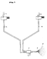
- FIG. 1 schematically shows the device according to the invention for processing multicomponent materials using the example of a two-component system.
- a first component is fed via lines 12 to a pumping and metering device 1.
- the medium to be pumped is heated to a certain temperature before it enters the pumping and metering device 1, at which an effective and problem-free pumping and / or metering is possible.
- the medium conveyed by the pumping and metering device 1 is fed via a line 13 to a first inlet of a two-component spray gun 4, which is a mixing device, e.g. B. has a static tube mixer or a forced rotor mixer.
- a mixing device e.g. B. has a static tube mixer or a forced rotor mixer.
- a second component is correspondingly fed via a line 22, a pumping and metering device 2 and a line 14 to a second input of the two-component spray gun 4.
- Lines 13 and 14 are designed as heating hoses.
- the components for example a polyol component and an isocyanate component of a two-component liquid elastomer, are brought together in the spray gun 4 and mixed ready for application.
- the pressure here is preferably 30 to 50 bar.
- the mixed components are guided and sprayed through a nozzle core 6, preferably without air support. It is advantageous here that, due to the low spray pressure, the sprayed particles 5 of the two-component medium do not absorb any air during the spraying.
- the pumping and metering devices 1 and 2 each have at least one axial piston pump.
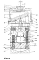
- Such an axial piston pump is shown in section.
- the drive shaft 30 is firmly connected to the drive pulley 8, in the example shown a swashplate. Driven by the drive pulley 8 rotating about the axis of the drive shaft 30, all the pistons mounted in the cylinder block 40 carry out stroke movements against the force of springs 17 provided in the respective pistons.
- the feed line or suction line 12 shown in FIG. 1 is connected to suction valve 22 (FIG. 2).
- the left in Fig. 2 Piston 25 is at its top dead center, which means that the cylinder volume available to the medium to be conveyed is minimal.
- the liquid to be delivered is drawn in via the suction valve 22 in the left-hand cylinder chamber 50 due to the negative pressure resulting from the increase in volume.
- the piston 25 now moves to its bottom dead center, which means that the cylinder volume available to the liquid to be conveyed is at a maximum. This state is shown for the cylinder 51 on the right in FIG. 2.
- the liquid to be pumped is conveyed via a pressure valve (not shown) via an outlet 27 and a pressure chamber 28 to the line 13 or 14 shown in FIG. 1.
- valve dead points are formed on the suction valve 22 between the suction valve ball 21 and the valve seat 21a. This results in sudden pressure pulses in the pump outlet 27, 28, which lead to an uneven delivery rate of the pump.
- a pulsation chamber 29 is provided above the pressure chamber 27, a back pressure membrane 18 being arranged between the pulsation chamber 29 and the pressure chamber 27.
- the back pressure membrane 18 is supported in the pulsation chamber 28 by a liquid or a gaseous medium.
- the pressurization of the medium located in the pulsation chamber 28 can be individually adapted to the substance to be conveyed.
- the delivery rate can be monitored by means of a volume flow meter (not shown), which can be connected to lines 13 or 14, for example.
- the volume flow meters used forward their measured values, for example volume flow cycles, to a computer unit.
- the computer unit is connected to a control unit for controlling the pump drive.
- the media From the volume flow meter, the media then enter the respective connecting lines 13 and 14, which can be designed as heating hoses. In this way, the components can be brought to their respective processing or mixing temperature.
- the funding route, d. H. the length of the lines 13 or 14 to a spray gun 4 can be up to 100 m.
- sealing lip rings 14 are provided on the tops of the cylinders 50, 51. These sealing lip rings 14 are preferably V-shaped or wedge-shaped, and are held in position by a support ring 12 and an expansion ring 15. Advantageously, the V- or wedge-shaped sealing rings with their tips towards the side facing away from the pressure, i. H. 2 arranged upwards.
- the sealing lip rings 14 can be re-tensioned via a plate spring 16. When the pistons 25 move upward, medium adhering to them is stripped off by the sealing lip rings. This largely avoids media to be conveyed entering the drive disk chamber 26, where they could lead to damage, for example due to abrasion.
- alkanesulfonates or alkanesulfonic acid esters is particularly preferred.
- This lubricant or separating agent is sealed against leakage via flat seals 27 and oil seals 1, 2.
- the axial piston pump can be effectively protected against wear by a combination of the sealing lip ring arrangement and the provision of such a release agent in the drive disk chamber. This is particularly important when abrasive or pigmented media are to be conveyed by the axial piston pump.
- the cylinder head is connected to the drive pulley housing 10 via support bearings 12. This makes it possible to replace one of these two components in a particularly simple manner. This can save costs.
Landscapes
- Engineering & Computer Science (AREA)
- Mechanical Engineering (AREA)
- General Engineering & Computer Science (AREA)
- Reciprocating Pumps (AREA)
- Application Of Or Painting With Fluid Materials (AREA)
- Nozzles (AREA)
- Compressors, Vaccum Pumps And Other Relevant Systems (AREA)
- Details Of Reciprocating Pumps (AREA)
Applications Claiming Priority (2)
| Application Number | Priority Date | Filing Date | Title |
|---|---|---|---|
| DE19618128A DE19618128A1 (de) | 1996-05-06 | 1996-05-06 | Vorrichtung zur Verarbeitung von viskosen Mehrkomponenten-Elastomeren |
| DE19618128 | 1996-05-06 |
Publications (1)
| Publication Number | Publication Date |
|---|---|
| EP0806567A2 true EP0806567A2 (fr) | 1997-11-12 |
Family
ID=7793468
Family Applications (1)
| Application Number | Title | Priority Date | Filing Date |
|---|---|---|---|
| EP97106991A Withdrawn EP0806567A2 (fr) | 1996-05-06 | 1997-04-28 | Dispositif de traitement d'élastomères visqueuses à multiples composants |
Country Status (3)
| Country | Link |
|---|---|
| EP (1) | EP0806567A2 (fr) |
| JP (1) | JPH1085657A (fr) |
| DE (1) | DE19618128A1 (fr) |
Cited By (3)
| Publication number | Priority date | Publication date | Assignee | Title |
|---|---|---|---|---|
| CN105257499A (zh) * | 2015-09-24 | 2016-01-20 | 成都西屋科技发展有限公司 | 多组份微量计量泵及其实现方法 |
| EP3238901A1 (fr) * | 2016-04-29 | 2017-11-01 | Polyplan-GmbH Polyurethan-Maschinen | Bloc fonctionnel pour une installation de polyuréthane |
| CN109382267A (zh) * | 2018-11-17 | 2019-02-26 | 大连华工创新科技股份有限公司 | 一种同时打开或关闭的胶阀涂胶头或注胶头 |
Families Citing this family (4)
| Publication number | Priority date | Publication date | Assignee | Title |
|---|---|---|---|---|
| GB2348252B (en) * | 1999-03-20 | 2003-10-15 | Nu Image Packaging | Apparatus for dispensing fluids |
| DE60018183D1 (de) * | 2000-09-26 | 2005-03-24 | Nu Image Packaging Clwyd Ltd A | Vorrichtung zum Abgeben von Flüssigkeiten |
| DE102010024560A1 (de) * | 2010-06-22 | 2011-12-22 | Fts Fluid-Technik & Systeme Gmbh | Dosierpumpe |
| FR3065378B1 (fr) * | 2017-04-19 | 2021-11-26 | Exel Ind | Dispositif comprenant une pompe a pistons axiaux pour l'application d'un produit fluide sur un substrat |
-
1996
- 1996-05-06 DE DE19618128A patent/DE19618128A1/de not_active Withdrawn
-
1997
- 1997-04-28 EP EP97106991A patent/EP0806567A2/fr not_active Withdrawn
- 1997-05-06 JP JP9151477A patent/JPH1085657A/ja active Pending
Cited By (4)
| Publication number | Priority date | Publication date | Assignee | Title |
|---|---|---|---|---|
| CN105257499A (zh) * | 2015-09-24 | 2016-01-20 | 成都西屋科技发展有限公司 | 多组份微量计量泵及其实现方法 |
| EP3238901A1 (fr) * | 2016-04-29 | 2017-11-01 | Polyplan-GmbH Polyurethan-Maschinen | Bloc fonctionnel pour une installation de polyuréthane |
| CN109382267A (zh) * | 2018-11-17 | 2019-02-26 | 大连华工创新科技股份有限公司 | 一种同时打开或关闭的胶阀涂胶头或注胶头 |
| CN109382267B (zh) * | 2018-11-17 | 2023-12-01 | 大连华工创新科技股份有限公司 | 一种同时打开或关闭的胶阀涂胶头或注胶头 |
Also Published As
| Publication number | Publication date |
|---|---|
| JPH1085657A (ja) | 1998-04-07 |
| DE19618128A1 (de) | 1997-11-13 |
Similar Documents
| Publication | Publication Date | Title |
|---|---|---|
| DE2821593C2 (de) | Zweistufenpumpe | |
| EP0463007B1 (fr) | Dispositif pour appliquer des agents traitant les vegetaux | |
| DE2921490A1 (de) | Kraftstoffeinspritzsteuersystem fuer verbrennungsmotoren | |
| EP1039011A2 (fr) | Dispositif et procédé pour l'apport d'un liquide de traitement sur un fil textile en défilement | |
| CH669826A5 (fr) | ||
| DE102007037780A1 (de) | Konstantdruckdüse | |
| DE3127831A1 (de) | "system und vorrichtung zum pumpen" | |
| EP0806567A2 (fr) | Dispositif de traitement d'élastomères visqueuses à multiples composants | |
| DE102015012170B4 (de) | Vorrichtung und Verfahren zum Auftragen eines flüssigen oder pastösen Mediums auf ein Objekt | |
| EP0736689A1 (fr) | Ensemble de pompes de dosage et d'injection | |
| DE3837325A1 (de) | Fluessigkeits-kolbenpumpe fuer chromatographische analysegeraete | |
| DE1288433B (de) | Verfahren und Vorrichtung zur UEbertragung von Energie eines Antriebsmediums auf eine angetriebenes Medium | |
| EP0647458B1 (fr) | Dispositif mélangeur pour ajouter des additifs à un liquide | |
| DE29623917U1 (de) | Vorrichtung zur Verarbeitung von viskosen Mehrkomponenten-Elastomeren | |
| DE1553127A1 (de) | Verfahren zum Foerdern eines konstanten Fluessigkeitsstroms und nach dem Verfahren arbeitende Zumesspumpe | |
| EP1348487B1 (fr) | Installation de revêtement avec un pulvérisateur et un pompe de dosage | |
| DE3600534A1 (de) | Pumpenaggregat fuer eine beschichtungsanlage | |
| EP3643397B1 (fr) | Dispositif d'homogénéisation d'un produit et utilisation dudit dispositif pour l'homogénéisation d'un produit | |
| DE2255986C3 (de) | Pumpeinrichtung für eine Hydraulikanlage in einem Kraftfahrzeug | |
| DE3026788C2 (de) | Dichtungsanordnung | |
| DE2622771A1 (de) | Hochdruckpumpe | |
| DE4320541A1 (de) | Vorrichtung zum Verspritzen von Spritzgut unter hohem Druck | |
| DE19524048C2 (de) | Pumpe zur Förderung nicht fließfähiger Medien | |
| DE4439641C1 (de) | Verfahren zum Schneiden von Lebensmitteln sowie Vorrichtung zur Durchführung des Verfahrens | |
| DE29623922U1 (de) | Vorrichtung zur Verarbeitung von viskosen Mehrkomponenten-Elastomeren |
Legal Events
| Date | Code | Title | Description |
|---|---|---|---|
| PUAI | Public reference made under article 153(3) epc to a published international application that has entered the european phase |
Free format text: ORIGINAL CODE: 0009012 |
|
| AK | Designated contracting states |
Kind code of ref document: A2 Designated state(s): AT BE CH DE DK ES FI FR GB GR IE IT LI LU NL PT SE |
|
| STAA | Information on the status of an ep patent application or granted ep patent |
Free format text: STATUS: THE APPLICATION IS DEEMED TO BE WITHDRAWN |
|
| 18D | Application deemed to be withdrawn |
Effective date: 19991103 |