EP0806380A1 - Verfahren und Vorrichtung zum Ordnen von Produkten - Google Patents
Verfahren und Vorrichtung zum Ordnen von Produkten Download PDFInfo
- Publication number
- EP0806380A1 EP0806380A1 EP97107560A EP97107560A EP0806380A1 EP 0806380 A1 EP0806380 A1 EP 0806380A1 EP 97107560 A EP97107560 A EP 97107560A EP 97107560 A EP97107560 A EP 97107560A EP 0806380 A1 EP0806380 A1 EP 0806380A1
- Authority
- EP
- European Patent Office
- Prior art keywords
- products
- product
- station
- transfer
- unit
- Prior art date
- Legal status (The legal status is an assumption and is not a legal conclusion. Google has not performed a legal analysis and makes no representation as to the accuracy of the status listed.)
- Granted
Links
- 238000000034 method Methods 0.000 title claims abstract description 15
- 238000011144 upstream manufacturing Methods 0.000 claims description 9
- 230000002093 peripheral effect Effects 0.000 description 5
- 238000012856 packing Methods 0.000 description 3
- 235000013305 food Nutrition 0.000 description 2
- 244000299461 Theobroma cacao Species 0.000 description 1
- 235000019219 chocolate Nutrition 0.000 description 1
- 230000009897 systematic effect Effects 0.000 description 1
Images
Classifications
-
- B—PERFORMING OPERATIONS; TRANSPORTING
- B65—CONVEYING; PACKING; STORING; HANDLING THIN OR FILAMENTARY MATERIAL
- B65G—TRANSPORT OR STORAGE DEVICES, e.g. CONVEYORS FOR LOADING OR TIPPING, SHOP CONVEYOR SYSTEMS OR PNEUMATIC TUBE CONVEYORS
- B65G47/00—Article or material-handling devices associated with conveyors; Methods employing such devices
- B65G47/22—Devices influencing the relative position or the attitude of articles during transit by conveyors
- B65G47/26—Devices influencing the relative position or the attitude of articles during transit by conveyors arranging the articles, e.g. varying spacing between individual articles
- B65G47/28—Devices influencing the relative position or the attitude of articles during transit by conveyors arranging the articles, e.g. varying spacing between individual articles during transit by a single conveyor
- B65G47/29—Devices influencing the relative position or the attitude of articles during transit by conveyors arranging the articles, e.g. varying spacing between individual articles during transit by a single conveyor by temporarily stopping movement
-
- B—PERFORMING OPERATIONS; TRANSPORTING
- B65—CONVEYING; PACKING; STORING; HANDLING THIN OR FILAMENTARY MATERIAL
- B65G—TRANSPORT OR STORAGE DEVICES, e.g. CONVEYORS FOR LOADING OR TIPPING, SHOP CONVEYOR SYSTEMS OR PNEUMATIC TUBE CONVEYORS
- B65G47/00—Article or material-handling devices associated with conveyors; Methods employing such devices
- B65G47/02—Devices for feeding articles or materials to conveyors
- B65G47/04—Devices for feeding articles or materials to conveyors for feeding articles
- B65G47/06—Devices for feeding articles or materials to conveyors for feeding articles from a single group of articles arranged in orderly pattern, e.g. workpieces in magazines
- B65G47/08—Devices for feeding articles or materials to conveyors for feeding articles from a single group of articles arranged in orderly pattern, e.g. workpieces in magazines spacing or grouping the articles during feeding
- B65G47/082—Devices for feeding articles or materials to conveyors for feeding articles from a single group of articles arranged in orderly pattern, e.g. workpieces in magazines spacing or grouping the articles during feeding grouping articles in rows
-
- B—PERFORMING OPERATIONS; TRANSPORTING
- B65—CONVEYING; PACKING; STORING; HANDLING THIN OR FILAMENTARY MATERIAL
- B65G—TRANSPORT OR STORAGE DEVICES, e.g. CONVEYORS FOR LOADING OR TIPPING, SHOP CONVEYOR SYSTEMS OR PNEUMATIC TUBE CONVEYORS
- B65G47/00—Article or material-handling devices associated with conveyors; Methods employing such devices
- B65G47/22—Devices influencing the relative position or the attitude of articles during transit by conveyors
- B65G47/26—Devices influencing the relative position or the attitude of articles during transit by conveyors arranging the articles, e.g. varying spacing between individual articles
- B65G47/30—Devices influencing the relative position or the attitude of articles during transit by conveyors arranging the articles, e.g. varying spacing between individual articles during transit by a series of conveyors
- B65G47/31—Devices influencing the relative position or the attitude of articles during transit by conveyors arranging the articles, e.g. varying spacing between individual articles during transit by a series of conveyors by varying the relative speeds of the conveyors forming the series
Definitions
- the present invention relates to a method of ordering products.
- the present invention relates to a method of ordering products as they are fed onto a machine.
- the present invention is particularly advantageous for use in the food packing industry, for packing products such as chocolates or similar, to which the following description refers purely by way of example.
- products are supplied to a machine featuring an input conveying device having a number of conveying elements, which are fed at a given rate and with a given timing through a loading station where each receives a respective product.
- the products are normally supplied in an orderly manner to the conveying device by means of a supply line, of which the conveying device forms the end element.
- Known supply lines normally comprise an ordering device for feeding a succession of products in a given traveling direction at said frequency, and for gradually bringing the products into contact with one another to form a continuous column of products for supply to a pickup station; and a transfer device extending between the pickup and loading stations, and which feeds the products to the loading station in time with said conveying elements.
- the ordering device of known supply lines of the above type is normally defined by a conveyor belt
- the transfer device is normally defined by a wheel mounted for rotation about an axis crosswise to the traveling direction, and having a succession of equally spaced peripheral suction seats alternating with respective peripheral blow openings, and which are fed through the pickup and loading stations in time with the conveying elements.
- Each suction seat provides for engaging and removing the first product in the column from the pickup station in time with a respective conveying element, while the peripheral blow openings suspend removal of the products from the pickup station and temporarily arrest the whole column if the first product in the column is already located at the pickup station.
- temporary stoppage of the column is not accompanied by a corresponding stoppage of the conveyor belt, this slides beneath and gradually damages the products.
- more recent transfer devices feature, in place of the suction seats, a number of orientable heads, each having a respective gripping element, and each orientable in relation to the traveling direction of the products by means of a control unit controlled by a photocell located at one end of the conveyor belt to detect transit of the products.
- the control unit On receiving a product transit signal, calculates the difference between the position of the product and the position of the respective gripping element in relation to the pickup station, and so orients the head as to advance or delay passage of the gripping element through the pickup station.
- a method of ordering products as the products are supplied, in a given direction and along a given path, to a conveying device having a number of conveying elements movable through a loading station at a given frequency and with a given timing to each receive a respective product; the method comprising the steps of feeding said products successively at said frequency and with any timing up to a transfer station located upstream from said loading station in said direction; and transferring said products from the transfer station to the loading station at said frequency to feed the products to the loading station in time with respective conveying elements; the method being characterized in that said transfer step comprises the substeps of feeding each product into a respective supply pocket, the pocket having a given stop portion, and a dimension, measured in said direction, greater than a dimension of the products measured in the same direction; moving each product inside the respective pocket to position the product precisely at the respective stop portion; and feeding each stop portion through said loading station in time with the relative conveying element.
- the present invention also relates to a unit for feeding products in an orderly manner to a machine.
- a unit for ordering products comprising supply means for feeding the products, in a given direction and along a given path, to a conveying device having a number of conveying elements movable through a loading station at a given frequency and with a given timing to each receive a respective product; conveying means for successively feeding said products at said frequency and with any timing up to a transfer station located upstream from said loading station in said direction; and transfer means for transferring said products from the transfer station to the loading station at said frequency, to feed the products to the loading station in time with respective conveying elements; the unit being characterized in that said transfer means comprise at least one supply pocket for receiving a respective product at the transfer station, the pocket having a given stop portion, and a dimension, measured in said direction, greater than a dimension of the products measured in the same direction; and actuating means for moving each product inside the respective pocket to precisely position the product at the respective stop portion; each stop portion being fed, in use, through said loading station in time with the relative conveying element.
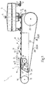
- Number 1 in Figure 1 indicates a unit for ordering products 2 and for feeding products 2 to a conveying device 3 in a direction D and along a given path P.
- Conveying device 3 comprises a number of known gripping or loading heads 4 equally spaced about a vertical axis of rotation 5 of conveying device 3, and which are fed at a given frequency F and with a given timing J through a loading station 6.
- Unit 1 comprises a supply device 7 and a transfer device 8 in series with each other along path P, and which cooperate with each other to feed products 2 along path P at frequency F to conveying device 3. More specifically, transfer device 8 receives products 2 from supply device 7 at a transfer station 9 located upstream from station 6 in direction D, and feeds each product 2 to station 6 in time with a respective gripping head 4.
- Device 7 receives products 2 from a known ordering device (not shown) for arranging products 2 substantially contacting one another, and feeds products 2 successively with any timing up to station 9.
- Supply device 7 comprises a conveyor belt 10 narrower than products 2 so that the lateral end portions of products 2 project outwards of belt 10, and which is looped about a powered pulley 11 and an idle pulley 12, which are fitted in rotary manner to a frame 13 and define, on belt 10, a transportation branch 14 extending along path P up to station 9.
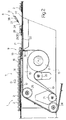
- Device 7 also comprises a plate 15 extending beneath branch 14 between pulleys 11 and 12, and having a shaped upper profile 16 substantially contacting branch 14. More specifically, and as shown clearly in Figure 2, profile 16 comprises an initial horizontal portion 17 aligned with a peripheral tangent of pulley 12; and a vertical end portion 18 aligned with a peripheral tangent of pulley 11 and connected to portion 17 by an inclined portion 19 located at station 9 so that transportation branch 14 slopes downwards in direction D. Finally, device 7 comprises a pair of takeup pulleys 20 and 21, the first of which is located outwards of belt 10, between pulleys 21 and 11 and close to pulley 11, and is fitted to frame 13 by means of a known elastic support (not shown).
- Transfer device 8 comprises a pair of identical conveyor belts 22 (only one shown) located on either side of belt 10 and looped about four pairs of pulleys 23, 24, 25, 26 fitted in rotary manner to frame 13; pulleys 23 are integral with each other and define a single drive pulley for driving belts 22; pulleys 24 are located substantially at pulley 21, beneath transportation branch 14; pulleys 25 are located beneath portion 17 of plate 15, upstream from station 9 in direction D; and pulleys 26 are located at station 6, and define, on belts 22 and together with pulleys 25, respective horizontal transportation branches 27 extending along path P from station 9 to station 6, and lower than both branch 14 and gripping heads 4 of conveying device 3, so that: at station 9, branches 27 are located directly alongside a bottom end of inclined portion 19 of plate 15; and, at station 6, heads 4, in use, travel facing branches 27, and are located over branches 27 at a height substantially equal to a thickness of products 2.
- Belts 22 comprise a number of supply pockets 28, each of which receives a respective product 2 at station 9 in such a manner that said lateral end portions of product 2 contact belts 22, and each of which comprises a dimension, measured in direction D, greater than a dimension of product 2 also measured in direction D. More specifically, each pocket 28 receives a respective product 2 with a variable amount of slack in direction D, and comprises a stop portion 29, which is fed through station 6 at frequency F and with timing J, hence in time with heads 4, and is defined by two projections 30 (only one shown) extending outwards from respective belts 22 and of a thickness less than the difference in the level of transportation branches 14 and 27 of belts 10 and 22 at station 9.
- device 8 comprises brake means in the form of a positioning device 31 located over branch 27, upstream from station 6 in direction D, and for braking each product 2 to move the product 2 inside respective pocket 28 and into a position adjacent to projections 30, so that product 2 is supplied to station 6 in perfect time with relative gripping head 4.
- brake means 31 are pneumatic, and comprise a push element 32 defined by a nozzle 33 pointing in the opposite direction to the traveling direction of products 2, and connected to a known pneumatic device (not shown) to direct a jet 34 of air onto products 2 and move the products 2 inside respective pockets 28 into a position adjacent to and contacting projections 30.
- the frequency F at which products 2 are fed along path P is imposed at all times by conveying device 3, which feeds heads 4 through station 6 at frequency F and at a given speed V having a component, in direction D, at least equal to a traveling speed V1 of pockets 28 along path P.
- transfer device 8 feeds pockets 28 through stations 9 and 6 at frequency F, so that each head 4 always receives a product 2 from respective pocket 28 at station 6, while supply device 7 feeds products 2 to station 9 at frequency F, so that each pocket 28 always receives a product 2.
- the operating frequency of unit 1 is adjusted according to any change in frequency F of conveying device 3 by means of a known control unit (not shown) commonly used for this purpose and connected to the drives of devices 3, 7 and 8.
- supply device 7 feeds products 2 successively and substantially continuously to station 9 at a speed V2 lower than speed V1, and feeds them to transfer device 8 at station 9 by transferring them from branch 14 directly into respective pockets 28. That is, since transportation branches 14 and 27 of respective belts 10 and 22 are located at different levels, and since branch 14 is guided by plate 15 - in particular, by inclined portion 19 of plate 15 - so as to be inserted between branches 27, device 7 feeds products 2 directly into pockets 28, at any point along pockets 28 with respect to respective projections 30.
- each product 2 is deposited gradually inside respective pocket 28. That is, inclined portion 19, which is of a length equal to said dimension of product 2 measured in direction D, ensures product 2 contacts belts 22 before projections 30 reach station 9. As such, on contacting belts 22, product 2 is not only accelerated from speed V2 to speed V1, but is also distanced from the following product 2 to enable relative projections 30 to be positioned between the two products 2. The distance, measured in direction D, between two adjacent products 2 on branches 27 inside pockets 28 is therefore greater than the distance, measured in direction D, between two products 2 on branch 14.
- transfer device 8 feeds products 2 to station 6, where heads 4 of conveying device 3 receive products 2 and transfer them from station 6 to the input of a machine (not shown), e.g. a wrapping machine.
- a machine e.g. a wrapping machine.
- unit 1 provides for timing products 2 with respect to heads 4 in a straightforward and particularly effective manner with no need for sophisticated control systems.
- push element 32 of brake means 31 is replaced by a pneumatic plate located upstream from station 6 in direction D, between branches 27, and having a number of holes connected to a pneumatic device for forming an air cushion over the plate to detach products 2 slightly from belts 22.
- the loss in speed of products 2 with respect to belts 22 during detachment moves products 2 gradually inside respective pockets 28 to position products 2 against respective projections 30.
- pneumatic brake means 31 are replaced by friction brake means, and push element 32 is replaced by a straightforward fixed plate located upstream from station 6 in direction D and along path P between branches 27.
- the upper surface of the fixed plate is located at a slightly higher level than branches 27, so as to detach products 2 from belts 22 at that point along path P, cause a loss in speed of products 2 as they slide along the upper surface, and so position products 2 correctly against respective projections 30.
Landscapes
- Engineering & Computer Science (AREA)
- Mechanical Engineering (AREA)
- Specific Conveyance Elements (AREA)
- Organic Low-Molecular-Weight Compounds And Preparation Thereof (AREA)
- Attitude Control For Articles On Conveyors (AREA)
Applications Claiming Priority (2)
| Application Number | Priority Date | Filing Date | Title |
|---|---|---|---|
| IT96BO000254A IT1285692B1 (it) | 1996-05-08 | 1996-05-08 | Metodo ed unita' per l'ordinamento di prodotti |
| ITBO960254 | 1996-05-08 |
Publications (2)
| Publication Number | Publication Date |
|---|---|
| EP0806380A1 true EP0806380A1 (de) | 1997-11-12 |
| EP0806380B1 EP0806380B1 (de) | 2003-04-16 |
Family
ID=11341390
Family Applications (1)
| Application Number | Title | Priority Date | Filing Date |
|---|---|---|---|
| EP97107560A Expired - Lifetime EP0806380B1 (de) | 1996-05-08 | 1997-05-07 | Verfahren und Vorrichtung zum Ordnen von Produkten |
Country Status (4)
| Country | Link |
|---|---|
| US (1) | US5915523A (de) |
| EP (1) | EP0806380B1 (de) |
| DE (1) | DE69720845T2 (de) |
| IT (1) | IT1285692B1 (de) |
Cited By (3)
| Publication number | Priority date | Publication date | Assignee | Title |
|---|---|---|---|---|
| WO1999032392A3 (en) * | 1997-12-22 | 1999-09-02 | Mcdonalds Corp | Automated beverage system |
| WO2015169783A1 (de) * | 2014-05-05 | 2015-11-12 | Wood-Flame Gmbh | Verfahren und vorrichtung zur qualitätskontrolle von stetig gefördertem stückgut |
| WO2016147151A1 (en) * | 2015-03-19 | 2016-09-22 | Gdm S.P.A. | Grouping unit and method to form groups of hygiene absorbent articles in a packaging machine |
Families Citing this family (10)
| Publication number | Priority date | Publication date | Assignee | Title |
|---|---|---|---|---|
| NL1006370C2 (nl) * | 1997-06-20 | 1998-12-22 | Kloeckner Haensel Tevopharm | Transportinrichting voor het versnellen van een reeks producten. |
| SE517272C2 (sv) * | 1999-10-12 | 2002-05-21 | Flexlink Components Ab | Anordning och förfarande för styrning av enheter i ett flöde |
| US6511062B1 (en) | 2000-02-07 | 2003-01-28 | Lockheed Martin Corporation | Presentation control for flat article singulation mechanism and sensors suitable for use therewith |
| US6662929B1 (en) | 2000-11-17 | 2003-12-16 | Lockhead Martin Corporation | Parcel singulation software control logic |
| US6711462B2 (en) * | 2002-03-05 | 2004-03-23 | Lockheed Martin Corporation | System and method for collating items |
| FR2859714B1 (fr) * | 2003-09-12 | 2005-11-11 | Aries Packaging | Procede de formation et d'espacement de lots successifs d'articles |
| EP1626004A1 (de) * | 2004-07-15 | 2006-02-15 | CAVANNA S.p.A. | Vorrichtung und Verfahren zum Herstellen von Gruppen von Gegenständen in Fördersystemen, insbesondere für automatische Verpackungsmaschinen |
| CN101052577A (zh) * | 2004-10-22 | 2007-10-10 | Fps食品加工公司 | 定位传送带 |
| DE102007005550A1 (de) * | 2007-01-25 | 2008-07-31 | Manfred Haiss | Einrichtung zum Umsetzen von Stückgütern |
| DE102009011302A1 (de) * | 2009-03-02 | 2010-09-09 | Kuka Roboter Gmbh | Vereinzeln von Gebindelagen |
Citations (5)
| Publication number | Priority date | Publication date | Assignee | Title |
|---|---|---|---|---|
| DE2346407A1 (de) * | 1972-09-15 | 1974-03-21 | Mario Cavanna | Vorrichtung zur regulierung der zufuhr von gegenstaenden zu einer verpackungsmaschine |
| DE3604806A1 (de) * | 1986-02-15 | 1987-08-20 | Helmut Staufner | Vorrichtung zum registrieren bzw. erfassen vereinzelter gegenstaende |
| EP0519400A1 (de) * | 1991-06-21 | 1992-12-23 | G.D Societa' Per Azioni | Vorrichtung zum abstandsgleichen Fördern von zufallsverteilt zugeführten Produkten |
| EP0572097A1 (de) * | 1992-05-27 | 1993-12-01 | Mafo Howden B.V. | Waschvorrichtung |
| EP0608861A2 (de) * | 1993-01-29 | 1994-08-03 | Pactec Verpackungsmaschinen-Fabrik Theegarten GmbH & Co. KG | Verfahren und Einrichtung zum Zuführen empfindlicher Gegenstände zu einer Verarbeitungsmaschine |
Family Cites Families (15)
| Publication number | Priority date | Publication date | Assignee | Title |
|---|---|---|---|---|
| US1299198A (en) * | 1918-11-26 | 1919-04-01 | David Low | Feeder especially adapted for asparagus-handling machines. |
| US2580086A (en) * | 1950-02-21 | 1951-12-25 | Fried Steel Equipment Mfg Corp | Strip conveyer |
| US3348655A (en) * | 1966-12-06 | 1967-10-24 | Kliklok Corp | Device for disentangling and conveying flanged receptacles |
| US3523603A (en) * | 1967-08-11 | 1970-08-11 | Bangor Punta Operations Inc | Conveyor table |
| US3667622A (en) * | 1970-08-17 | 1972-06-06 | Keller & Co C | Method of and means for stacking moulded articles in groups |
| US3721330A (en) * | 1971-02-08 | 1973-03-20 | Fmc Corp | Article timing and feeding mechanism |
| IT970180B (it) * | 1972-11-02 | 1974-04-10 | Cavanna M | Dispositivo per l abbinamento di prodotti e relativi imbalaggi durante l alimentazione di una macchina confezionatrice |
| FI48569C (fi) * | 1973-06-06 | 1974-11-11 | Rysti & Co Ab | Sahatun puutavaran annostelumenetelmä ja -laite. |
| US3901375A (en) * | 1974-02-04 | 1975-08-26 | Fmc Corp | Package feeding and timing mechanism |
| US3971481A (en) * | 1975-04-21 | 1976-07-27 | Roberto Gonzalez Barrera | Materials handling apparatus |
| US4077524A (en) * | 1976-05-19 | 1978-03-07 | Alpo Rysti | Apparatus for sequentially forwarding bodies to a conveyer |
| US4124113A (en) * | 1977-06-09 | 1978-11-07 | The Lodge & Shipley Company | Case indexer |
| DE3662592D1 (en) * | 1985-06-26 | 1989-05-03 | Sig Schweiz Industrieges | Apparatus for separating articles being in contact with each other |
| CH686363A5 (de) * | 1992-03-16 | 1996-03-15 | Martin Lehmann | Foerderanlage. |
| IT1273840B (it) * | 1994-11-11 | 1997-07-11 | Azionaria Costruzioni Acma Spa | Metodo e linea per l'alimentazione a passo di prodotti |
-
1996
- 1996-05-08 IT IT96BO000254A patent/IT1285692B1/it active IP Right Grant
-
1997
- 1997-05-07 US US08/852,393 patent/US5915523A/en not_active Expired - Fee Related
- 1997-05-07 DE DE69720845T patent/DE69720845T2/de not_active Expired - Lifetime
- 1997-05-07 EP EP97107560A patent/EP0806380B1/de not_active Expired - Lifetime
Patent Citations (5)
| Publication number | Priority date | Publication date | Assignee | Title |
|---|---|---|---|---|
| DE2346407A1 (de) * | 1972-09-15 | 1974-03-21 | Mario Cavanna | Vorrichtung zur regulierung der zufuhr von gegenstaenden zu einer verpackungsmaschine |
| DE3604806A1 (de) * | 1986-02-15 | 1987-08-20 | Helmut Staufner | Vorrichtung zum registrieren bzw. erfassen vereinzelter gegenstaende |
| EP0519400A1 (de) * | 1991-06-21 | 1992-12-23 | G.D Societa' Per Azioni | Vorrichtung zum abstandsgleichen Fördern von zufallsverteilt zugeführten Produkten |
| EP0572097A1 (de) * | 1992-05-27 | 1993-12-01 | Mafo Howden B.V. | Waschvorrichtung |
| EP0608861A2 (de) * | 1993-01-29 | 1994-08-03 | Pactec Verpackungsmaschinen-Fabrik Theegarten GmbH & Co. KG | Verfahren und Einrichtung zum Zuführen empfindlicher Gegenstände zu einer Verarbeitungsmaschine |
Non-Patent Citations (1)
| Title |
|---|
| FERRIS & ANZELONE: "in-line substrate escapement", I.B.M. TECHNICAL DISCLOSURE BULLETIN, vol. 10, no. 2, July 1967 (1967-07-01), pages 148, XP002027599 * |
Cited By (8)
| Publication number | Priority date | Publication date | Assignee | Title |
|---|---|---|---|---|
| WO1999032392A3 (en) * | 1997-12-22 | 1999-09-02 | Mcdonalds Corp | Automated beverage system |
| US6102246A (en) * | 1997-12-22 | 2000-08-15 | Restaurant Technology, Inc. | Automated beverage system |
| EP1207131A1 (de) * | 1997-12-22 | 2002-05-22 | Restaurant Technology, Inc. | Automatische Getränkeabgabevorrichtung |
| EP1199279A3 (de) * | 1997-12-22 | 2002-08-21 | Restaurant Technology, Inc. | Becherförderer für automatische Getränkeabgabevorrichtung |
| CN1107639C (zh) * | 1997-12-22 | 2003-05-07 | 饭店技术公司 | 自动饮料系统及其杯输送器和杯储存和分配组件 |
| WO2015169783A1 (de) * | 2014-05-05 | 2015-11-12 | Wood-Flame Gmbh | Verfahren und vorrichtung zur qualitätskontrolle von stetig gefördertem stückgut |
| WO2016147151A1 (en) * | 2015-03-19 | 2016-09-22 | Gdm S.P.A. | Grouping unit and method to form groups of hygiene absorbent articles in a packaging machine |
| US10683116B2 (en) | 2015-03-19 | 2020-06-16 | Gdm S.P.A. | Grouping unit and method to form groups of hygiene absorbent articles in a packaging machine |
Also Published As
| Publication number | Publication date |
|---|---|
| DE69720845T2 (de) | 2003-12-18 |
| ITBO960254A0 (it) | 1996-05-08 |
| US5915523A (en) | 1999-06-29 |
| ITBO960254A1 (it) | 1997-11-08 |
| IT1285692B1 (it) | 1998-06-18 |
| EP0806380B1 (de) | 2003-04-16 |
| DE69720845D1 (de) | 2003-05-22 |
Similar Documents
| Publication | Publication Date | Title |
|---|---|---|
| US5915523A (en) | Method and unit for ordering products | |
| US6889485B2 (en) | Article grouping mechanism | |
| JP3868490B2 (ja) | 多数個パックの包装装置 | |
| EP0994025B1 (de) | Verfahren und Einheit zum Herstellen einer Gruppe von Gegenständen in einer Einschachtelmaschine | |
| EP0711719B1 (de) | Verfahren zum abstandsgleichen Fördern von Produkten und Förderband dazu | |
| EP1300351B1 (de) | Verfahren und Vorrichtung zum geordneten Abführen von ungeordnet zugeführten Produkten | |
| WO2012064277A1 (en) | Transition device | |
| EP1270459B1 (de) | Einheit zum Zuführen von Produkten in einer geordneten Reihenfolge zu einer Entladestation | |
| US6669006B2 (en) | Method and device for conveying reams of paper | |
| CN106660711B (zh) | 用于输送块式产品的方法和装置 | |
| EP0413997B1 (de) | Vorrichtung zum Zuführen von Gegenständen von einer Beschickungseinheit an eine Empfangseinheit | |
| KR100630541B1 (ko) | 이송장치 | |
| EP1447357B1 (de) | Anordnungsvorrichtung für feste Gegenstände | |
| US4354591A (en) | Carton collating and transfer apparatus | |
| EP0825118B1 (de) | Verfahren zum Bilden von Gruppen von Paketen | |
| EP1365979B1 (de) | Eingruppierungsmaschine | |
| EP1144280A2 (de) | Vorrichtung zum auseinanderdrücken auf vorgegebene abstände von kunststoffbehältern | |
| EP0814036A2 (de) | Scharnierbandförderer | |
| JPH0569940A (ja) | 物品蓄積装置 | |
| JPH0683631U (ja) | 仕分装置 | |
| HK1028973B (en) | Transfer mechanism |
Legal Events
| Date | Code | Title | Description |
|---|---|---|---|
| PUAI | Public reference made under article 153(3) epc to a published international application that has entered the european phase |
Free format text: ORIGINAL CODE: 0009012 |
|
| AK | Designated contracting states |
Kind code of ref document: A1 Designated state(s): CH DE GB IT LI NL |
|
| 17P | Request for examination filed |
Effective date: 19980502 |
|
| 17Q | First examination report despatched |
Effective date: 20020125 |
|
| GRAH | Despatch of communication of intention to grant a patent |
Free format text: ORIGINAL CODE: EPIDOS IGRA |
|
| GRAH | Despatch of communication of intention to grant a patent |
Free format text: ORIGINAL CODE: EPIDOS IGRA |
|
| GRAA | (expected) grant |
Free format text: ORIGINAL CODE: 0009210 |
|
| AK | Designated contracting states |
Designated state(s): CH DE GB IT LI NL |
|
| REG | Reference to a national code |
Ref country code: GB Ref legal event code: FG4D |
|
| REG | Reference to a national code |
Ref country code: CH Ref legal event code: EP |
|
| REF | Corresponds to: |
Ref document number: 69720845 Country of ref document: DE Date of ref document: 20030522 Kind code of ref document: P |
|
| REG | Reference to a national code |
Ref country code: CH Ref legal event code: NV Representative=s name: MOINAS & SAVOYE SA |
|
| PLBE | No opposition filed within time limit |
Free format text: ORIGINAL CODE: 0009261 |
|
| STAA | Information on the status of an ep patent application or granted ep patent |
Free format text: STATUS: NO OPPOSITION FILED WITHIN TIME LIMIT |
|
| 26N | No opposition filed |
Effective date: 20040119 |
|
| PGFP | Annual fee paid to national office [announced via postgrant information from national office to epo] |
Ref country code: NL Payment date: 20060524 Year of fee payment: 10 |
|
| PG25 | Lapsed in a contracting state [announced via postgrant information from national office to epo] |
Ref country code: NL Free format text: LAPSE BECAUSE OF NON-PAYMENT OF DUE FEES Effective date: 20071201 |
|
| NLV4 | Nl: lapsed or anulled due to non-payment of the annual fee |
Effective date: 20071201 |
|
| PGFP | Annual fee paid to national office [announced via postgrant information from national office to epo] |
Ref country code: GB Payment date: 20120525 Year of fee payment: 16 |
|
| GBPC | Gb: european patent ceased through non-payment of renewal fee |
Effective date: 20130507 |
|
| PG25 | Lapsed in a contracting state [announced via postgrant information from national office to epo] |
Ref country code: GB Free format text: LAPSE BECAUSE OF NON-PAYMENT OF DUE FEES Effective date: 20130507 |
|
| PGFP | Annual fee paid to national office [announced via postgrant information from national office to epo] |
Ref country code: CH Payment date: 20140527 Year of fee payment: 18 Ref country code: IT Payment date: 20140526 Year of fee payment: 18 Ref country code: DE Payment date: 20140529 Year of fee payment: 18 |
|
| REG | Reference to a national code |
Ref country code: DE Ref legal event code: R119 Ref document number: 69720845 Country of ref document: DE |
|
| REG | Reference to a national code |
Ref country code: CH Ref legal event code: PL |
|
| PG25 | Lapsed in a contracting state [announced via postgrant information from national office to epo] |
Ref country code: IT Free format text: LAPSE BECAUSE OF NON-PAYMENT OF DUE FEES Effective date: 20150507 Ref country code: CH Free format text: LAPSE BECAUSE OF NON-PAYMENT OF DUE FEES Effective date: 20150531 Ref country code: LI Free format text: LAPSE BECAUSE OF NON-PAYMENT OF DUE FEES Effective date: 20150531 |
|
| PG25 | Lapsed in a contracting state [announced via postgrant information from national office to epo] |
Ref country code: DE Free format text: LAPSE BECAUSE OF NON-PAYMENT OF DUE FEES Effective date: 20151201 |