EP0413997B1 - Vorrichtung zum Zuführen von Gegenständen von einer Beschickungseinheit an eine Empfangseinheit - Google Patents
Vorrichtung zum Zuführen von Gegenständen von einer Beschickungseinheit an eine Empfangseinheit Download PDFInfo
- Publication number
- EP0413997B1 EP0413997B1 EP90114587A EP90114587A EP0413997B1 EP 0413997 B1 EP0413997 B1 EP 0413997B1 EP 90114587 A EP90114587 A EP 90114587A EP 90114587 A EP90114587 A EP 90114587A EP 0413997 B1 EP0413997 B1 EP 0413997B1
- Authority
- EP
- European Patent Office
- Prior art keywords
- conveyor
- products
- conveyor belt
- soaps
- fact
- Prior art date
- Legal status (The legal status is an assumption and is not a legal conclusion. Google has not performed a legal analysis and makes no representation as to the accuracy of the status listed.)
- Expired - Lifetime
Links
- 239000011295 pitch Substances 0.000 claims description 9
- 239000000344 soap Substances 0.000 description 44
- 241000252254 Catostomidae Species 0.000 description 8
- 238000004519 manufacturing process Methods 0.000 description 5
- 239000000463 material Substances 0.000 description 2
- 235000014653 Carica parviflora Nutrition 0.000 description 1
- 241000243321 Cnidaria Species 0.000 description 1
- 238000000151 deposition Methods 0.000 description 1
- 238000003780 insertion Methods 0.000 description 1
- 230000037431 insertion Effects 0.000 description 1
- 238000012856 packing Methods 0.000 description 1
- 239000007779 soft material Substances 0.000 description 1
Images


Classifications
-
- B—PERFORMING OPERATIONS; TRANSPORTING
- B65—CONVEYING; PACKING; STORING; HANDLING THIN OR FILAMENTARY MATERIAL
- B65G—TRANSPORT OR STORAGE DEVICES, e.g. CONVEYORS FOR LOADING OR TIPPING, SHOP CONVEYOR SYSTEMS OR PNEUMATIC TUBE CONVEYORS
- B65G17/00—Conveyors having an endless traction element, e.g. a chain, transmitting movement to a continuous or substantially-continuous load-carrying surface or to a series of individual load-carriers; Endless-chain conveyors in which the chains form the load-carrying surface
- B65G17/26—Conveyors having an endless traction element, e.g. a chain, transmitting movement to a continuous or substantially-continuous load-carrying surface or to a series of individual load-carriers; Endless-chain conveyors in which the chains form the load-carrying surface comprising a series of co-operating units, e.g. interconnected by pivots
-
- B—PERFORMING OPERATIONS; TRANSPORTING
- B65—CONVEYING; PACKING; STORING; HANDLING THIN OR FILAMENTARY MATERIAL
- B65G—TRANSPORT OR STORAGE DEVICES, e.g. CONVEYORS FOR LOADING OR TIPPING, SHOP CONVEYOR SYSTEMS OR PNEUMATIC TUBE CONVEYORS
- B65G47/00—Article or material-handling devices associated with conveyors; Methods employing such devices
- B65G47/22—Devices influencing the relative position or the attitude of articles during transit by conveyors
- B65G47/26—Devices influencing the relative position or the attitude of articles during transit by conveyors arranging the articles, e.g. varying spacing between individual articles
- B65G47/30—Devices influencing the relative position or the attitude of articles during transit by conveyors arranging the articles, e.g. varying spacing between individual articles during transit by a series of conveyors
- B65G47/32—Applications of transfer devices
-
- B—PERFORMING OPERATIONS; TRANSPORTING
- B65—CONVEYING; PACKING; STORING; HANDLING THIN OR FILAMENTARY MATERIAL
- B65G—TRANSPORT OR STORAGE DEVICES, e.g. CONVEYORS FOR LOADING OR TIPPING, SHOP CONVEYOR SYSTEMS OR PNEUMATIC TUBE CONVEYORS
- B65G2201/00—Indexing codes relating to handling devices, e.g. conveyors, characterised by the type of product or load being conveyed or handled
- B65G2201/02—Articles
Definitions
- the present invention relates to a device for feeding products from a supply unit to a receiving unit.
- the present invention may be advantageously employed for soap packing systems, for feeding the soaps, equally spaced, from the manufacturing to the wrapping machine.
- the soaps leaving the manufacturing machine are fed randomly spaced and usually by means of a conveyor belt to a device by which they are equally spaced.
- One such device picks up the soaps successively off the conveyor belt by means of suction heads fitted with suckers.
- the suction heads are arranged equally spaced and designed to pick up the soaps off the conveyor belt as they travel, at a different speed from the suction heads, beneath the respective suckers.
- the soaps picked up in substantially equally spaced manner by the suction heads are then inserted successively inside equally spaced compartments on a second conveyor belt by which they are fed to the wrapping unit.
- a transfer device between a supply unit and a receiving unit comprising an intermediate transfer conveyor and two further positioning conveyors cooperating with the transfer conveyor, and capable of performing a stop-and-go motion to set at a constant pitch a plurality of products advanced randomly by the supply unit.
- one of the positioning conveyors has a stopping member, which stops each product on the transfer conveyor, and releases such product only when it is separated from the preceding product by a predetermined distance.
- the above transfer device is absolutely unsuitable both for handling soaps, and for use in combination with a modern soap wrapping machine.
- the pitch adjustment is, in fact, obtained by stopping in succession the products on a continuously moving transfer conveyor. If the products are soaps, and the transfer conveyor is a fast moving conveyor as it would be required to feed a soap wrapping machine capable of handling more than ten soaps per second, the wear between the soaps and the transfer conveyor would be unbearable.
- the stop-and-go action performed by the two positioning conveyors may be suitable for positioning a product every few seconds, but is completely out of question when more than ten products per second are to be positioned.
- a transfer device between a supply unit and a receiving unit is known.
- Said device comprises a main conveyor having a succession of equally spaced L-shaped pocket elements each adapted to accommodate a respective product, and an auxiliary conveyor which has a succession of equally spaced confining elements shaped as an inverted L.
- the auxiliary conveyor merges with the main conveyor at a path portion, along which each inverted-L-shaped element cooperates with a corresponding L-shaped element to define a fixed-length compartment, the width of which varies continuously to a final width value corresponding to a final shape of the compartment.
- the above known device though advantageously used to conform a product made of soft material to the final shape of the aforementioned compartment, cannot be used to adjust the spacing of a succession of products, since the length of the compartments remains constant, and a misplaced product may either jam the device or be cut in two by the merging inverted-L-shaped element. It is therefore an object of the present invention to provide a device for feeding products, in particular soaps, from a supply unit to a receiving unit, said device providing an accurate positioning and equally spacing of said products prior to feeding the same to the receiving unit.
- each compartment is adjustable in its size, when measured in said traveling direction, between a first value exceeding that of said products at a transfer position where said products are transferred onto said supporting elements and into said compartments, and a second value substantially equal to the size of said products at a position located downstream from said transfer position; and the pitch ratio between said supporting elements and said positioning elements is equal to the speed ratio between said first and second conveyors.
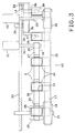
- Number 1 in Fig.1 indicates a device for transferring soaps 2 from a supply unit, consisting of a soap manufacturing machine indicated schematically by block 3, to a receiving unit consisting of a wrapping machine indicated schematically by block 4.
- Manufacturing machine 3 feeds soaps 2 successively and in randomly spaced manner onto a horizontal conveyor belt 5 by which soaps 2 are fed onto a further horizontal conveyor belt 6 located beneath a known conveying device 7 designed to equally space soaps 2 and of the type described in Italian Patent Application N° 3679A/88.
- Conveying device 7 substantially comprises a number of equally spaced, vertically operating suction heads 8 fitted on the bottom with respective suckers 9. Suction heads 8 are supported on two chains 10 and 11, each looped about two powered vertical gears (not shown) for moving suction heads 8 over and in the same direction as conveyor belt 6.
- Suckers 9 operate vertically in relation to respective heads 8, for successively picking up soaps 2 off conveyor belt 6, by virtue of known actuating means (not shown), and successively depositing the same inside respective compartments 12 on a horizontal conveying device 13 located downstream from conveyor belt 6. Prom conveyor 13, soaps 2 are fed successively on to a horizontal conveyor belt 14 by which they are fed into wrapping machine 4.
- conveyor device 13 comprises two conveyor means consisting of conveyor belts 15 and 16, the latter substantially housed inside the former, and the top branches of which are substantially horizontal and coplanar.
- Conveyor 15 comprises a belt 17 looped about an idle roller 18 supported on a shaft 19 in turn supported on bed 20 of device 1, and about a roller 21 fitted on to a shaft 22 parallel to shaft 19 and connected to a motor or drive means 23.
- belt 17 supports a number of laterally projecting, equally spaced supporting elements 24 having substantially the same spacing as suction heads 8 along conveyor 15 and extending inwards from belt 17 (Fig.2).
- Each supporting element 24 comprises a base plate 25 connected to belt 17 and the rear portion of which (with reference to the traveling direction of conveyor 15) supports a reaction element or tab 26 perpendicular to plate 25 and the top branch of belt 17.
- Conveyor belt 16 comprises a belt 27 looped about an idle roller 28 fitted on to shaft 19 between roller 18 and bed 20 and smaller in diameter than roller 18, and about a roller 29 housed inside the loop defined by conveyor 15 and fitted on to a horizontal shaft 30 connected to a motor or drive means 31.
- Each positioning element 32 consists of a parallelepiped bar arranged crosswise in relation to belt 27, with its lateral surface adhering to the same. Each bar 32 defines, together with facing tab 26, one of said compartments 12.
- Conveyor belt 14 comprises a belt 33 located between conveyor 15 and bed 20, and looped about an idle roller 34 and a powered roller (not shown) located downstream from conveyor device 13 with reference to the traveling direction of the same.
- Roller 34 is supported on a horizontal shaft 35, beside a portion of the loop defined by conveyor 15, between roller 29 and roller 21.
- the outer surface of belt 33 is fitted with a number of projecting, equally spaced supporting elements 36 facing belt 17 and having substantially the same spacing as supporting elements 24.
- Each supporting element 36 substantially comprises a cylindrical body 37 perpendicular to the surface of belt 33 and connected to the same by a bracket 38, the free end of which supports a coral supporting plate 39.
- the speed at which belt 27 is driven by motor 31 is lower than that at which belt 17 is driven by motor 23, and belt 33 travels at the same speed as belt 17.
- the pitch ratio of supporting elements 24 and positioning elements 32 is preferably equal to the traveling speed ratio of conveyor belts 15 and 16.
- soaps 2 are fed successively and randomly spaced off manufacturing machine 3 on to conveyor belt 5 and from there on to conveyor belt 6.
- soaps 2 are picked up successively by suckers 9 on suction heads 8, and are substantially equally spaced to match the spacing of suckers 9.
- Soaps 2 are then inserted successively by suction heads 8 into compartments 12 of conveyor device 13, the length of said compartments 12, at the point wherein soaps 2 are transferred from conveyor device 7 and measured in the traveling direction of conveyor belt 15, is greater than that of soaps 2 measured in the same direction.
- Said difference in the length of compartments 12 and soaps 2 at the point wherein soaps 2 are loaded inside compartments 12 depends on the difference in speed between conveyor belts 15 and 16, which speed difference is so selected that, at the point wherein conveyor device 7 feeds soaps 2 into compartments 12, the distance between each tab 26 and the foregoing positioning element 32 is greater than the length of soaps 2 measured in said direction.
- soaps 2 are housed inside compartments 12 with tabs 26 flanking one side and positioning elements 32 flanking a second side opposite the first.
- positioning elements 32 traveling at a slower speed than respective supporting elements 24, the distance between positioning elements 32 and facing tabs 26 is gradually reduced so that the length of compartments 12 is substantially equal to that of soaps 2 at the point wherein soaps 2 are picked off conveyor device 13 by supporting elements 36 of conveyor belt 14.
- soaps 2 are essentially perfectly positioned and equally spaced on conveyor belt 15, from which they are fed successively onto conveyor belt 14 and then to wrapping machine 4.
- Device 1 as described above thus provides a conveyor to feed soaps 2 in an equally spaced manner from machine 3 to machine 4.
- location of supporting elements 24 inwards of belt 17 provides for smooth, gradual release of soaps 2 as these are fed on to conveyor belt 14.
- conveyor belt 16 may be located outside and over conveyor belt 15, between conveyor device 7 and belt 14, in which case, positioning elements 32 of conveyor belt 16 may still cooperate with tabs 26 of supporting elements 24 for defining the length of compartments 12.
- tabs 26 may be provided at the front portions of supporting elements 24 (with reference to the travelling direction of conveyor belt 15) and positioning elements 32 located in such a manner as to define the rear portions of compartments 12. In this case, conveyor belt 16 and positioning elements 32 will be operated at a greater speed than conveyor belt 15, so as to gradually reduce the length of compartments 12 by moving tabs 26 up to positioning elements 32.
- conveyor belts 15 and 16 may present other than straight, horizontal transportation surfaces, providing they are capable of receiving soaps 2 inside compartments of variable length as described above.
Landscapes
- Engineering & Computer Science (AREA)
- Mechanical Engineering (AREA)
- Detergent Compositions (AREA)
Claims (5)
- Vorrichtung zum Zuführen von Gegenständen (2) von einer Beschickungseinheit an eine Aufnahmeeinheit entlang eines im wesentlichen linearen Wegs, die folgendes aufweist: einen ersten (15) und einen zweiten (16) Endlosförderer mit übereinanderliegenden Förderertrums, die miteinander zusammenarbeiten und die in derselben Laufrichtung angetrieben werden; wobei der erste Förderer (15) ein Transportförderer ist, der so ausgebildet ist, daß er im wesentlichen gleich beabstandete Gegenstände (2) von der Beschickungseinheit empfängt und diese Gegenstände (2) trägt, während sie zur Empfangseinheit transportiert werden, wobei dieser erste Förderer (15) eine Anzahl Halteelemente (24) trägt, die mit einem ersten vorgegebenen gegenseitigen Abstand voneinander beabstandet sind; wobei der zweite Förderer (16) eine Anzahl Positionierelemente (32) aufweist, die gemäß einem zweiten vorgegebenen gegenseitigen Abstand voneinander beabstandet sind; wobei der erste (15) und der zweite (16) Förderer so angetrieben werden, daß sie sich auf kontinuierliche Weise mit einer ersten bzw. einer zweiten Geschwindigkeit bewegen; und wobei jedes Haltelemente (24) ein Anschlagelement (26) aufweist, das quer in bezug auf die Laufrichtung angeordnet ist, und einem jeweiligen Positionierelement (32) zugewandt ist, um zusammen mit diesem jeweiligen Positionierelement (32) ein Fach (12) zum Aufnehmen eines Gegenstands (2) festzulegen; dadurch gekennzeichnet, daß der erste und der zweite gegenseitige Abstand sich voneinander unterscheiden und die erste und die zweite Geschwindigkeit sich voneinander unterscheiden; wobei jedes Fach (12) größenmäßig, gemessen in der Laufrichtung, zwischen einem ersten Wert, der den der Gegenstände (2) an einer Übertragungsposition überschreitet, an der die Gegenstände (2) auf die Halteelement und in die Fächer (12) übertragen werden, und einem zweiten Wert einstellbar ist, der im wesentlichen der Größe der Gegenstände (2) entspricht, und zwar an einer Position stromabwärts bezüglich der Übertragungsposition; und wobei das Verhältnis der gegenseitigen Abstände der Haltelemente (24) und der gegenseitigen Abstände der Positionierelemente (32) dem Verhältnis zwischen den Geschwindigkeiten des ersten (15) und des zweiten Förderers (16) entspricht.
- Vorrichtung nach Anspruch 1, dadurch gekennzeichnet, daß der erste und der zweite Endlosförderer aus einem ersten (15) bzw. einem zweiten (16) Förderband bestehen.
- Vorrichtung nach Anspruch 2, dadurch gekennzeichnet, daß das zweite Förderband (16) im wesentlichen innerhalb der durch das erste Förderband (15) festgelegten Schleife untergebracht ist, wobei die Transportflächen des ersten (15) und des zweiten (16) Förderbands im wesentlichen koplanar sind.
- Vorrichtung nach einem der Ansprüche 2 oder 3, dadurch gekennzeichnet, daß die Haltelemente (24) innerhalb des ersten Förderbands (15) liegen.
- Vorrichtung nach einem der vorstehenden Ansprüche, dadurch gekennzeichnet, daß die Geschwindigkeit der ersten Fördereinrichtung (15) größer als die der zweiten Fördereinrichtung (16) ist.
Applications Claiming Priority (2)
| Application Number | Priority Date | Filing Date | Title |
|---|---|---|---|
| IT8903600A IT1233680B (it) | 1989-08-25 | 1989-08-25 | Apparecchiatura per alimentare prodotti da una unita' erogatrice ad una unita' ricevitrice |
| IT360089 | 1989-08-25 |
Publications (2)
| Publication Number | Publication Date |
|---|---|
| EP0413997A1 EP0413997A1 (de) | 1991-02-27 |
| EP0413997B1 true EP0413997B1 (de) | 1995-05-10 |
Family
ID=11110445
Family Applications (1)
| Application Number | Title | Priority Date | Filing Date |
|---|---|---|---|
| EP90114587A Expired - Lifetime EP0413997B1 (de) | 1989-08-25 | 1990-07-30 | Vorrichtung zum Zuführen von Gegenständen von einer Beschickungseinheit an eine Empfangseinheit |
Country Status (5)
| Country | Link |
|---|---|
| US (1) | US5096043A (de) |
| EP (1) | EP0413997B1 (de) |
| DE (1) | DE69019259T2 (de) |
| ES (1) | ES2071711T3 (de) |
| IT (1) | IT1233680B (de) |
Families Citing this family (11)
| Publication number | Priority date | Publication date | Assignee | Title |
|---|---|---|---|---|
| DE4243689A1 (de) * | 1992-12-18 | 1994-06-23 | Hans Dentler | Regeleinrichtung für einen Förderstrom |
| CA2138470C (en) * | 1993-12-28 | 2005-08-09 | Dean J. Mannlein | Adjustable bucket |
| IT1273840B (it) * | 1994-11-11 | 1997-07-11 | Azionaria Costruzioni Acma Spa | Metodo e linea per l'alimentazione a passo di prodotti |
| NL1006370C2 (nl) * | 1997-06-20 | 1998-12-22 | Kloeckner Haensel Tevopharm | Transportinrichting voor het versnellen van een reeks producten. |
| ITBO20040084A1 (it) * | 2004-02-19 | 2004-05-19 | Azionaria Costruzioni Acma Spa | Unita' per il convogliamento di prodotti |
| US20070059153A1 (en) * | 2005-09-14 | 2007-03-15 | Applied Materials, Inc. | Methods and apparatus for a transport lift assembly |
| DE102007021146A1 (de) * | 2007-05-03 | 2008-11-06 | Focke & Co.(Gmbh & Co. Kg) | Vorrichtung und Verfahren zum Handhaben von flachen Gegenständen, insbesondere Windeln |
| CN203132509U (zh) * | 2012-12-07 | 2013-08-14 | 富鼎电子科技(嘉善)有限公司 | 尺寸测试装置 |
| CN104803032A (zh) * | 2015-03-20 | 2015-07-29 | 浙江华诺化工有限公司 | 一种肥皂包装机供料输送装置 |
| DE102017206970A1 (de) * | 2017-04-26 | 2018-10-31 | Robert Bosch Gmbh | Vorrichtung und Verfahren zum Transport von Produkten insbesondere für Verpackungsmaschinen |
| CN109607245B (zh) * | 2018-12-28 | 2024-03-08 | 唐山智能电子有限公司 | 自动装车机水泥袋连包处理装置 |
Family Cites Families (10)
| Publication number | Priority date | Publication date | Assignee | Title |
|---|---|---|---|---|
| US2358292A (en) * | 1941-09-15 | 1944-09-12 | Redington Co F B | Conveyer |
| US3482674A (en) * | 1968-03-11 | 1969-12-09 | Emhart Corp | Conveyor system for handling groups of articles |
| IT968102B (it) * | 1972-12-18 | 1974-03-20 | Acma Spa | Apparato per ordinare a passo oggetti provenienti disordina tamente da una linea erogatrice e per trasferirli quindi ad una linea ricevitrice |
| US3868009A (en) * | 1973-03-29 | 1975-02-25 | Carle & Montanari Spa | Transferring device |
| FR2259750A1 (en) * | 1974-01-31 | 1975-08-29 | Pont A Mousson | Tray loading installation for tins - has overlying platforms for groups of tins and trays |
| US3932983A (en) * | 1974-09-26 | 1976-01-20 | R. A. Jones & Co. Inc. | Tamper and confiner for product bucket |
| IT1053104B (it) * | 1975-12-19 | 1981-08-31 | Azionaria Costruzioni Acma Spa | Apparato per trasferire..secondo un passo predeterminato..oggetti a un convogliatore di ricezione..gli oggetti provenendo ad intervalli irregolari da un convogliatore di erogazione |
| US4041822A (en) * | 1976-06-11 | 1977-08-16 | Gabel Floyd S | Sausage slicing machine |
| CH621529A5 (de) * | 1977-09-05 | 1981-02-13 | Sig Schweiz Industrieges | |
| FR2609973A1 (fr) * | 1987-01-27 | 1988-07-29 | Sapal Plieuses Automatiques | Dispositif de transfert de produits transportes par un convoyeur |
-
1989
- 1989-08-25 IT IT8903600A patent/IT1233680B/it active
-
1990
- 1990-07-30 ES ES90114587T patent/ES2071711T3/es not_active Expired - Lifetime
- 1990-07-30 DE DE69019259T patent/DE69019259T2/de not_active Expired - Fee Related
- 1990-07-30 EP EP90114587A patent/EP0413997B1/de not_active Expired - Lifetime
- 1990-07-31 US US07/560,355 patent/US5096043A/en not_active Expired - Lifetime
Also Published As
| Publication number | Publication date |
|---|---|
| US5096043A (en) | 1992-03-17 |
| DE69019259T2 (de) | 1996-01-25 |
| DE69019259D1 (de) | 1995-06-14 |
| EP0413997A1 (de) | 1991-02-27 |
| IT8903600A0 (it) | 1989-08-25 |
| ES2071711T3 (es) | 1995-07-01 |
| IT1233680B (it) | 1992-04-14 |
Similar Documents
| Publication | Publication Date | Title |
|---|---|---|
| US5310041A (en) | Device for equally-spaced transportation of randomly arranged incoming products | |
| EP0413997B1 (de) | Vorrichtung zum Zuführen von Gegenständen von einer Beschickungseinheit an eine Empfangseinheit | |
| CA1138485A (en) | Device for piling-up flat workpieces, especially blanks for folding boxes | |
| US7581637B2 (en) | Feeding device for a packaging machine | |
| US6550608B1 (en) | Carton feeding system for packaging machine | |
| EP0806383B1 (de) | Verfahren und Vorrichtung zum geordneten Abführen von ungeordnet zugeführten Produkten | |
| EP0711719B1 (de) | Verfahren zum abstandsgleichen Fördern von Produkten und Förderband dazu | |
| US2542330A (en) | Conveyer system | |
| EP0994025B1 (de) | Verfahren und Einheit zum Herstellen einer Gruppe von Gegenständen in einer Einschachtelmaschine | |
| US6044959A (en) | Apparatus for staging (pitching) articles on a conveyor system | |
| EP0538765B1 (de) | Verfahren und Vorrichtung zum Bilden von Gruppen flacher Gegenstände, insbesondere Kekse, für die Zufuhr zu einer Verpackungsanlage | |
| GB2025884A (en) | Device for intermittently feeding articles to be packaged in packaging machines | |
| GB2213120A (en) | Apparatus for feeding articles to a working station | |
| US5409098A (en) | Apparatus for the transport of cigarette packs | |
| JPH0739297B2 (ja) | 可撓性の扁平な製品、特に印刷物をその処理装置に装入する装置 | |
| US6669006B2 (en) | Method and device for conveying reams of paper | |
| EP0806380B1 (de) | Verfahren und Vorrichtung zum Ordnen von Produkten | |
| EP0298957B1 (de) | Anordnung zur geordneten entnahme von gegenständen aus einem behälter | |
| EP0884254A1 (de) | Einrichtung zum gruppen- oder packweisen Fördern von Produkten | |
| JPS6236932B2 (de) | ||
| SE519496C2 (sv) | Förfarande och anordning för positionering av produkter i ett stationärt hanteringsläge | |
| EP0062618A2 (de) | Bandförderer, insbesondere zum Transport von langgestreckten Gegenständen, die quer zur Förderrichtung angeordnet sind | |
| EP0905065B1 (de) | Einheit zum Bilden und Befördern von Gegenstandsstapeln zu einer Maschine | |
| EP0143546A1 (de) | Apparat zum Entladen von Förderern | |
| US3501026A (en) | Article transfer apparatus for candy bars and the like |
Legal Events
| Date | Code | Title | Description |
|---|---|---|---|
| PUAI | Public reference made under article 153(3) epc to a published international application that has entered the european phase |
Free format text: ORIGINAL CODE: 0009012 |
|
| AK | Designated contracting states |
Kind code of ref document: A1 Designated state(s): DE ES FR GB |
|
| 17P | Request for examination filed |
Effective date: 19910730 |
|
| 17Q | First examination report despatched |
Effective date: 19930217 |
|
| GRAA | (expected) grant |
Free format text: ORIGINAL CODE: 0009210 |
|
| AK | Designated contracting states |
Kind code of ref document: B1 Designated state(s): DE ES FR GB |
|
| REF | Corresponds to: |
Ref document number: 69019259 Country of ref document: DE Date of ref document: 19950614 |
|
| REG | Reference to a national code |
Ref country code: ES Ref legal event code: FG2A Ref document number: 2071711 Country of ref document: ES Kind code of ref document: T3 |
|
| ET | Fr: translation filed | ||
| PLBE | No opposition filed within time limit |
Free format text: ORIGINAL CODE: 0009261 |
|
| STAA | Information on the status of an ep patent application or granted ep patent |
Free format text: STATUS: NO OPPOSITION FILED WITHIN TIME LIMIT |
|
| 26N | No opposition filed | ||
| REG | Reference to a national code |
Ref country code: GB Ref legal event code: IF02 |
|
| PGFP | Annual fee paid to national office [announced via postgrant information from national office to epo] |
Ref country code: FR Payment date: 20040720 Year of fee payment: 15 |
|
| PGFP | Annual fee paid to national office [announced via postgrant information from national office to epo] |
Ref country code: GB Payment date: 20040721 Year of fee payment: 15 |
|
| PGFP | Annual fee paid to national office [announced via postgrant information from national office to epo] |
Ref country code: ES Payment date: 20040809 Year of fee payment: 15 |
|
| PG25 | Lapsed in a contracting state [announced via postgrant information from national office to epo] |
Ref country code: GB Free format text: LAPSE BECAUSE OF NON-PAYMENT OF DUE FEES Effective date: 20050730 |
|
| PG25 | Lapsed in a contracting state [announced via postgrant information from national office to epo] |
Ref country code: ES Free format text: LAPSE BECAUSE OF NON-PAYMENT OF DUE FEES Effective date: 20050801 |
|
| GBPC | Gb: european patent ceased through non-payment of renewal fee |
Effective date: 20050730 |
|
| PG25 | Lapsed in a contracting state [announced via postgrant information from national office to epo] |
Ref country code: FR Free format text: LAPSE BECAUSE OF NON-PAYMENT OF DUE FEES Effective date: 20060331 |
|
| REG | Reference to a national code |
Ref country code: FR Ref legal event code: ST Effective date: 20060331 |
|
| REG | Reference to a national code |
Ref country code: ES Ref legal event code: FD2A Effective date: 20050801 |
|
| PGFP | Annual fee paid to national office [announced via postgrant information from national office to epo] |
Ref country code: DE Payment date: 20070831 Year of fee payment: 18 |
|
| PG25 | Lapsed in a contracting state [announced via postgrant information from national office to epo] |
Ref country code: DE Free format text: LAPSE BECAUSE OF NON-PAYMENT OF DUE FEES Effective date: 20090203 |