EP0806376B1 - Transporteur à rouleaux avec rouleaux supports pour les objets transportés - Google Patents
Transporteur à rouleaux avec rouleaux supports pour les objets transportés Download PDFInfo
- Publication number
- EP0806376B1 EP0806376B1 EP96250210A EP96250210A EP0806376B1 EP 0806376 B1 EP0806376 B1 EP 0806376B1 EP 96250210 A EP96250210 A EP 96250210A EP 96250210 A EP96250210 A EP 96250210A EP 0806376 B1 EP0806376 B1 EP 0806376B1
- Authority
- EP
- European Patent Office
- Prior art keywords
- support
- roller
- brake
- roller conveyor
- braking
- Prior art date
- Legal status (The legal status is an assumption and is not a legal conclusion. Google has not performed a legal analysis and makes no representation as to the accuracy of the status listed.)
- Expired - Lifetime
Links
Images

Classifications
-
- B—PERFORMING OPERATIONS; TRANSPORTING
- B65—CONVEYING; PACKING; STORING; HANDLING THIN OR FILAMENTARY MATERIAL
- B65G—TRANSPORT OR STORAGE DEVICES, e.g. CONVEYORS FOR LOADING OR TIPPING, SHOP CONVEYOR SYSTEMS OR PNEUMATIC TUBE CONVEYORS
- B65G13/00—Roller-ways
- B65G13/075—Braking means
-
- B—PERFORMING OPERATIONS; TRANSPORTING
- B65—CONVEYING; PACKING; STORING; HANDLING THIN OR FILAMENTARY MATERIAL
- B65G—TRANSPORT OR STORAGE DEVICES, e.g. CONVEYORS FOR LOADING OR TIPPING, SHOP CONVEYOR SYSTEMS OR PNEUMATIC TUBE CONVEYORS
- B65G47/00—Article or material-handling devices associated with conveyors; Methods employing such devices
- B65G47/22—Devices influencing the relative position or the attitude of articles during transit by conveyors
- B65G47/26—Devices influencing the relative position or the attitude of articles during transit by conveyors arranging the articles, e.g. varying spacing between individual articles
- B65G47/261—Accumulating articles
Definitions
- the invention relates to a roller conveyor with support rollers for the conveyed material according to the Preamble of claim 1.
- an accumulation roller conveyor is known whose idlers for conveying conveyed goods without back pressure driving or. can be stopped.
- the drive takes place via an endlessly rotating and in Flat belt running in the conveying direction, the upper run for the transmission of the Driving forces can be pressed from below onto the support rollers via support rollers.
- the support rollers are mounted eccentrically and viewed in the direction of conveyance arranged in the area between the support rollers which follow one another at a distance, so that the support rollers can be raised so far in the drive state that there is a slight looping of the idlers through the flat belt.
- the lifting movement of the support roller takes place by turning the eccentric bearing via a lever arranged radially for this purpose.
- the lever of a section of the Accumulation roller conveyor are each articulated on a common actuating bar, the via a pneumatic cylinder in or against the conveying direction of the accumulation roller conveyor are displaceable so as to lift the support rollers of a section together or lower.
- the rollers are braked using a brake belt that runs parallel to the Drive belt runs and is firmly clamped at its ends.
- the idlers are the brake belt in a similar manner as the drive belt additional support rollers pressed onto the support rollers from below.
- the support rollers for the Brake and drive belt are so eccentric on a common shaft stored that depending on the position of the lever either the support roller for the drive belt or the support roller for the brake belt in the raised or lowered state are located.
- each Carrier roller is assigned its own braking device.
- This braking device consists in essentially from a brake pad which is arranged on a brake pad carrier.
- the Brake pad has the same material thickness throughout and is in accordance with Radius of curvature of the idlers formed.
- the brake pad carrier with the brake pad can be adjusted via an actuating element in the direction of the support roller.
- French patent application FR 2 537 104 A1 is another Accumulation roller conveyor known, the driven accumulation roller section for one of the idlers has a braking device.
- This braking device is essentially made of one Brake pad built up, which is supported on a support element which is used to put on the Brake pad on the surface of the idler roller and at the same time in the direction of rotation of the Carrier roller is adjustable. The brake pad is caused by the rotation of the idler and the adjusting movement of the support element is compressed.
- the present invention has for its object to provide a roller conveyor To create braking elements that offer optimized braking performance.
- the design of the eccentric drives proves to be particularly simple in terms of construction from an eccentrically mounted eccentric disc, on which a lever engages radially is attached, the end facing away from the eccentric disc for rotating the Eccentric disc with a particularly designed as a pneumatic cylinder Linear drive means is connected.
- a preferred installation location for the brake elements has the arrangement on the half facing away from the material to be conveyed and largely proven on the rear side of the support roller as seen in the conveying direction, because of this the largely tangential to the idler roller surface required for the upsetting effect following last movement phase preferably almost parallel and opposite to Direction of funding can take place.
- the arrangement of only the brake elements for two inches is particularly advantageous Direction of conveyance successive idlers on a respective support element, which as Swing arm is formed between the brake elements for in the conveying direction successive idlers is pivotally mounted on an eccentric drive. This ensures that the braking force is evenly distributed over the idlers and at the same time possible due to the pivotable mounting of the support element Manufacturing tolerances that differ at different intervals between the Knock down braking elements and the surfaces of the idlers, thereby be balanced.
- One designed in this way is particularly suitable Braking device for rollers, the support rollers of which are close to each other exhibit. This enables the conveyed goods to be braked quickly and quietly.
- the support element designed as a rocker has proven to be particularly advantageous form such that the center of gravity of the support element between the Eccentric drive and one arranged at one end of the support element Stop element lies, so that in its rest position, in which the idlers are unbraked, the support element moves into a defined position. In this situation is the rear one in the conveying direction and on the one facing away from the stop element End of the support member arranged braking element with a smaller distance arranged to the surface of the associated idler roller as the front one Braking element.
- the stop element as a pin, which is in the Rest position of the support element on a slide bar, which is below the Carrying rollers and in the direction of conveyance and on which the levers of the eccentric drives a roller conveyor section and a linear drive means for the slide bar are articulated.
- a further improvement in braking performance is provided by the opening in the support element as an elongated hole, the longitudinal extension of which is parallel to the tangential direction of movement of the support element is achieved, because hereby the support element after the brake element has been gripped by the surface the idler pulley in the direction of rotation, d. H. largely tangential to Carrier roller surface is pulled until the eccentric at the other end of the elongated hole.
- For Achieving the upsetting effect is provided according to the device that the Bracket facing the braking surface of the braking element against the direction of rotation seen the idler and relative to the largely tangential movement of the Supporting element is seen rising.
- FIG. 1 shows a side view of a section of an accumulation roller conveyor Idlers 1 in the unbraked state.
- the accumulation roller conveyor essentially exists from two U-shaped side members 2 (see Figure 3), the open sides of each other are turned away. Between and on the webs of the longitudinal beams 2 are the idlers 1 stored, which form a flat support surface for the material to be conveyed 4 and their Rotation axes D run transversely to the conveying direction F and horizontally.
- Each support roller 1 is in a drive belt 3 in the form of a flat belt Direction of rotation d can be driven.
- the drive belt 3 is endlessly formed, wherein the upper strand from below against the support rollers 1 (see Figure 3) Carries idlers 1 via friction.
- This friction between the drive belt 3 and the idlers 1 is by lifting the upper run of the drive belt 3 in Direction of the support rollers 1 reached via support rollers 5, seen in the direction of conveyance F, are each arranged between the successive idlers 1 and thus in the raised state above the level formed by the support rollers 1 lower limit level can be raised. This will create an in Seen from the side, the undulating course of the drive belt 3 is reached and thus through the increased wrap of the idlers 1 an optimized transmission of Drive power reached.
- the support rollers 5 are one Accumulation roller conveyor section and a common linear drive means lowerable.
- the respective levers 7 of the support rollers 5 are articulated with their ends on a slide bar 9 that can be moved essentially in or against the conveying direction F. are articulated, which in turn is movable via the linear drive means.
- each support roller 1 has a braking element 10 sustainable, the cuboid and made of polyurethane elastomer is.
- the braking elements 10 for two consecutive in the conveying direction F.
- Carrier rollers 1 of an accumulation roller section are each on a common one Support element 11, which is designed as a rocker extending in the conveying direction F, arranged.
- the fastening of the two brake elements 10 on the support element 11 takes place in a form-fitting manner in recesses 12 on the upper side of the supporting element 11, which correspond to the shape of the brake elements 10.
- the support element 11 also designed to be raised and lowered via an eccentric drive.
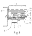
- the eccentric drive essentially consists of an eccentric disk 13, which is mounted eccentrically on the axis 6 and via the lever 7 of the support roller 5 is pivotable.
- On the eccentric disc 13 is designed as a rocker Support element 11 is pivotable in a correspondingly designed opening 14 stored and the eccentric 13 is seen in the conveying direction between the Idlers 1 arranged.
- the pivotal movement of the support member 11 is in the of the idlers 1 away rest position by a stop element 8, the Pen is formed, limited.
- the stop element 8 is in the rest position on the slide bar 9, since the center of gravity S of the support element 11 between the Stop element 8 and its opening 14 is located.
- the support member 11 therefore tilts also automatically after releasing the brake elements 10 from the idlers 1 in the Resting position.
- the support elements 11 with the Brake elements 10 initially largely in the direction of the surfaces of the idlers 1 movable.
- the rear brake element 10 adjusted to the support roller 1 and thereby the support element 11 about the axis 6 pivoted, whereby the front brake element 10 to the front idler 1 is created.
- the braking elements become more and more with an increasing movement more in a tangential to the surface of the idlers 1 and in their direction of rotation moving direction, so that in the last area of the positioning movement Brake elements 10 between the surfaces of the support rollers 1 and the support element 11 are pinched.
- the contact pressure of the braking elements 10 on the Surface of the idlers 1 effectively increased.
- the jamming or compression of the brake elements 10 is caused by that in the direction of largely tangential to the surface of the idlers 1 extending adjusting movement of the braking elements 10, which in the present case is largely horizontal, the surface of the support rollers 1 facing the Brake elements 10 is inclined toward the support roller 1.
- Direction of movement included angles ⁇ 5 ° - 10 °, preferably 7 °.
- This Boundary conditions are u. a. created in that the braking elements 10 at horizontal accumulation roller conveyor viewed from below and in the direction of conveyance F seen from behind to the idlers 1 are adjustable.
- the Braking effect by the setting of the brake elements 10 in the direction of rotation respective support roller 1 by a kind of entrainment effect for the braking element 10 favored, since this increases the clamping effect.
- FIG. 1 and 2 each showing a side view of a Section of an accumulation roller conveyor with idler rollers 1 in the unbraked state (see FIG. 1) and in the braked state (see Figure 2) show a braking process of the Funded goods 4 explained in more detail.
- the support rollers 1 are driven via the drive belt 3 and the brake elements 10 are lifted from the idlers 1, is used as an introduction the braking process via the linear drive means the sliding bar 9 in Delivery direction F shifted.
- FIG 3 which is a section through the figure 1 and 4 along the Section line I - I shows that the eccentric discs 13 and the support rollers 5 mounted on a common axis 6 and a common axis Lever 7 are rotatable on the axis.
Landscapes
- Engineering & Computer Science (AREA)
- Mechanical Engineering (AREA)
- Rollers For Roller Conveyors For Transfer (AREA)
- Attitude Control For Articles On Conveyors (AREA)
- Rolls And Other Rotary Bodies (AREA)
- Braking Arrangements (AREA)
Claims (12)
- Transporteur à rouleaux comportant des rouleaux de support pour les objets transportés et des éléments de freinage pour les rouleaux de support, pouvant être appliqués contre les rouleaux de support par des moyens de réglage et être libérés de ceux-ci, éléments qui s'appuient contre des éléments de support, les éléments de freinage (10), pour le freinage des rouleaux de support (1), étant à chaque fois déplaçables sur une voie de déplacement prédéfinie dans le sens de rotation (d) des rouleaux de support (1) et contre leur surface, de sorte que les éléments de freinage (10) sont comprimés entre la surface du rouleau de support (1) et l'élément de support (11),
caractérisé en ce que les éléments de freinage (10) pour deux rouleaux de support (1) successifs dans la direction de transport sont fixés, à chaque fois, sur un élément de support (11) qui est réalisé comme pièce oscillante, et la pièce oscillante est montée de façon pivotante entre les éléments de freinage (10). - Transporteur à rouleaux selon la revendication 1,
caractérisé en ce que les éléments de freinage (10) sont fixés sur les éléments de support (11), qui sont déplaçables par l'intermédiaire d'un entraínement excentrique pour freiner les rouleaux de support (1), l'entraínement excentrique est constitué généralement d'un disque d'excentrique (13) et d'un levier (7) s'engageant radialement sur celui-ci, dont l'extrémité opposée au disque d'excentrique (13), pour tourner le disque d'excentrique (13), est reliée à un moyen d'entraínement linéaire et, dans l'élément de support (11), il est agencé une ouverture (14) pour recevoir le disque d'excentrique (13). - Transporteur à rouleaux selon la revendication 2,
caractérisé en ce que la pièce oscillante est montée sur l'entraínement excentrique et, grâce à celui-ci, les éléments de freinage (10) pour freiner les rouleaux de support (1) peuvent être déplacés tout d'abord généralement en direction de la surface du rouleau de support (1) et ensuite généralement tangentiellement à la surface du rouleau de support (1). - Transporteur à rouleaux selon la revendication 3,
caractérisé en ce que le mouvement de pivotement de l'élément de support (11) est limité dans une direction par un élément de butée (8) et le centre de gravité (S) de l'élément de support (11) se trouve entre l'élément de butée (8) et l'entraínement excentrique, de sorte que l'élément de support (11), dans sa position de repos dans laquelle les rouleaux de support (1) ne sont pas freinés, est pivoté autour de l'entraínement excentrique en direction de l'élément de butée (8), et l'élément de freinage (10) arrière dans la direction de transport (F) et agencé à l'extrémité de l'élément de support (11) opposée à l'élément de butée (8) présente un plus faible écartement par rapport à la surface associée du rouleau de support (1) que l'élément de freinage (10) sur le côté opposé de l'élément de support (11). - Transporteur à rouleaux selon la revendication 4,
caractérisé en ce que l'élément de butée (8) est réalisé sous forme de goupille qui s'appuie dans la position de repos de l'élément de support (11), sur une barrette de poussée (9) qui s'étend au-dessous des rouleaux de support (1) et dans la direction de transport (F) et sur laquelle les leviers (7) des entraínements excentriques d'un tronçon du transporteur à rouleaux d'accumulation, ainsi qu'un moyen d'entraínement linéaire, sont montés de façon articulée. - Transporteur à rouleaux selon la revendication 4 ou 5,
caractérisé en ce que le mouvement de pivotement de l'élément de support (11) entre la position de repos et la position de freinage se trouve dans la plage entre 0,5° et 5°. - Transporteur à rouleaux selon une des revendications 1 à 6,
caractérisé en ce que le mouvement, s'étendant généralement tangentiellement, des éléments de freinage (10) est orienté parallèlement à la direction de transport (F). - Transporteur à rouleaux selon une des revendications 2 à 7,
caractérisé en ce que chaque ouverture (14) dans l'élément de support (11) est réalisée comme trou oblong dont l'extension longitudinale est orientée parallèlement à la direction de déplacement tangentielle de l'élément de support (11), et l'élément de support (11) est précontraint dans la direction de transport par l'intermédiaire d'un élément élastique (8) engageant le disque d'excentrique (13). - Transporteur à rouleaux selon une des revendications 1 à 8,
caractérisé en ce que les éléments de freinage (10) peuvent s'appuyer, à chaque fois, contre la moitié, opposée aux objets transportés (4), des rouleaux de support (1) et généralement contre la face arrière dans la direction de transport (F) des rouleaux de support (1). - Transporteur à rouleaux selon une des revendications 1 à 9,
caractérisé en ce que la surface de freinage, en regard du rouleau de support (1), de l'élément de freinage (10) monte à l'encontre du sens de rotation (d) du rouleau de support (1) et relativement au déplacement généralement tangentiel de l'élément de support (11). - Transporteur à rouleaux selon la revendication 10,
caractérisé en ce que l'angle (α) défini entre la surface de freinage, en regard du rouleau de support (1), de l'élément de freinage (10) et la direction de déplacement généralement tangentielle de l'élément de support (11) vaut environ entre 5 et 10°. - Transporteur à rouleaux selon une des revendications 1 à 11,
caractérisé en ce que les éléments de freinage (10) sont fabriqués en élastomère de polyuréthane.
Applications Claiming Priority (4)
| Application Number | Priority Date | Filing Date | Title |
|---|---|---|---|
| DE19619097 | 1996-05-06 | ||
| DE19619097 | 1996-05-06 | ||
| DE19628711A DE19628711C2 (de) | 1996-05-06 | 1996-07-08 | Staurollenbahn |
| DE19628711 | 1996-07-08 |
Publications (2)
| Publication Number | Publication Date |
|---|---|
| EP0806376A1 EP0806376A1 (fr) | 1997-11-12 |
| EP0806376B1 true EP0806376B1 (fr) | 2001-05-23 |
Family
ID=26025629
Family Applications (2)
| Application Number | Title | Priority Date | Filing Date |
|---|---|---|---|
| EP96250210A Expired - Lifetime EP0806376B1 (fr) | 1996-05-06 | 1996-09-25 | Transporteur à rouleaux avec rouleaux supports pour les objets transportés |
| EP97250144A Expired - Lifetime EP0806377B1 (fr) | 1996-05-06 | 1997-04-28 | Convoyeur accumulateur à rouleaux |
Family Applications After (1)
| Application Number | Title | Priority Date | Filing Date |
|---|---|---|---|
| EP97250144A Expired - Lifetime EP0806377B1 (fr) | 1996-05-06 | 1997-04-28 | Convoyeur accumulateur à rouleaux |
Country Status (3)
| Country | Link |
|---|---|
| EP (2) | EP0806376B1 (fr) |
| AT (2) | ATE201375T1 (fr) |
| DK (2) | DK0806376T3 (fr) |
Families Citing this family (2)
| Publication number | Priority date | Publication date | Assignee | Title |
|---|---|---|---|---|
| CN114803279B (zh) * | 2022-04-25 | 2023-09-22 | 老肯医疗科技股份有限公司 | 一种清洗架输送系统及其输送方法 |
| CN115648328B (zh) * | 2022-09-30 | 2023-09-01 | 连云港师达工艺品有限公司 | 一种带有废料收集机构的eva片材切割装置及其收集方法 |
Family Cites Families (8)
| Publication number | Priority date | Publication date | Assignee | Title |
|---|---|---|---|---|
| US4006815A (en) * | 1974-11-11 | 1977-02-08 | Alvey Inc. | Article transporting conveyor |
| FR2537104A1 (fr) * | 1982-12-03 | 1984-06-08 | Gallet Sa | Transporteur a rouleaux commandes comportant un systeme de debrayage et de freins |
| AT384595B (de) * | 1983-03-24 | 1987-12-10 | Tgw Transportgeraete Gmbh | Rollenbahn |
| DE3418205C2 (de) * | 1984-05-16 | 1986-04-10 | psb GmbH Förderanlagen und Lagertechnik, 6780 Pirmasens | Staurollenförderer |
| DE3738587A1 (de) | 1987-11-13 | 1989-05-24 | H & K Verpackungstechnik Gmbh | Verfahren und vorrichtung zum abstandsgerechten zuteilen von stueckguetern |
| DE3817388C1 (fr) | 1988-05-19 | 1989-07-06 | Mannesmann Ag, 4000 Duesseldorf, De | |
| EP0640540B1 (fr) * | 1993-08-31 | 1999-11-10 | Steiff Fördertechnik GmbH | Dispositif et procédé pour convoyer des articles sur des rouleaux parallèles et à émerillon rotatif |
| DE4409968C2 (de) | 1994-03-23 | 1997-01-23 | Gebhardt Foerdertech | Bausatz zum Bremsen der Tragrollen von Rollenförderern |
-
1996
- 1996-09-25 EP EP96250210A patent/EP0806376B1/fr not_active Expired - Lifetime
- 1996-09-25 DK DK96250210T patent/DK0806376T3/da active
- 1996-09-25 AT AT96250210T patent/ATE201375T1/de not_active IP Right Cessation
-
1997
- 1997-04-28 DK DK97250144T patent/DK0806377T3/da active
- 1997-04-28 AT AT97250144T patent/ATE200064T1/de active
- 1997-04-28 EP EP97250144A patent/EP0806377B1/fr not_active Expired - Lifetime
Also Published As
| Publication number | Publication date |
|---|---|
| ATE200064T1 (de) | 2001-04-15 |
| EP0806376A1 (fr) | 1997-11-12 |
| EP0806377B1 (fr) | 2001-03-28 |
| EP0806377A1 (fr) | 1997-11-12 |
| DK0806376T3 (da) | 2001-08-06 |
| ATE201375T1 (de) | 2001-06-15 |
| DK0806377T3 (da) | 2001-04-30 |
Similar Documents
| Publication | Publication Date | Title |
|---|---|---|
| AT414329B (de) | Übergabeeinrichtung für stückhaftes fördergut | |
| EP0743267A1 (fr) | Roue convoyeuse à étoile pour récipients | |
| WO1986002622A1 (fr) | Transporteur a chaine pour pieces a usiner ou pour supports de pieces a usiner | |
| DE3202382C2 (de) | Reversierbare Stauförderbahn | |
| EP0960842A1 (fr) | Convoyeur à rouleaux avec des rouleaux de support entrainés | |
| DE2645883C3 (de) | Förderhängebahn zum Transport, Sammeln und Verteilen von Laufkatzen | |
| EP0806376B1 (fr) | Transporteur à rouleaux avec rouleaux supports pour les objets transportés | |
| EP0161412B1 (fr) | Dispositif de transport pour convoyer des montages supports de pièces | |
| EP0999168A2 (fr) | Dispositif de freinage à double action pour ascenseurs ou dispositifs de desserte de rayonnage | |
| DE102006010795A1 (de) | Vorrichtung zum Aufweiten von Metallelementen | |
| DE2003785A1 (de) | Sammelfoerdervorrichtung | |
| DE19628711C2 (de) | Staurollenbahn | |
| DE19850678C1 (de) | Doppel-Bremsfangvorrichtung für Aufzüge oder Regalbediengeräte (RBG) | |
| DE1297022B (de) | Roellchenbahnweiche | |
| DE3820328C2 (de) | Bremse für einen OE-Spinnrotor | |
| DE1943778C3 (de) | Fördervorrichtung, mit der auf einer Förderbahn ankommende Reifenrohlinge an die Greifer eines Hängeförderers einer Spritzanlage o.dgl. abgegeben werden | |
| DE10204260A1 (de) | Stauförderer | |
| DE3134577A1 (de) | Elektrische schneidmaschine | |
| DE19852040C1 (de) | Doppel-Bremsfangvorrichtung für Aufzüge oder Regalbediengeräte (RBG) | |
| EP1190966B1 (fr) | Dispositif de transport | |
| DE19940059C2 (de) | Doppel-Bremsfangvorrichtung für Aufzüge oder Regalbediengeräte (RBG) | |
| DE2354767A1 (de) | Antriebsvorrichtung fuer einen foerderstrang | |
| EP1218271B1 (fr) | Dispositif pour tourner une pile de papier | |
| DE2260718B2 (de) | Kurvengaengiger bandfoerderer | |
| DE3316256A1 (de) | Sicherheits-banduebergabe zwischen stetigfoerderern unterschiedlicher bauart |
Legal Events
| Date | Code | Title | Description |
|---|---|---|---|
| PUAI | Public reference made under article 153(3) epc to a published international application that has entered the european phase |
Free format text: ORIGINAL CODE: 0009012 |
|
| AK | Designated contracting states |
Kind code of ref document: A1 Designated state(s): AT DE DK FR GB IT NL |
|
| 17P | Request for examination filed |
Effective date: 19971113 |
|
| 17Q | First examination report despatched |
Effective date: 19990329 |
|
| GRAG | Despatch of communication of intention to grant |
Free format text: ORIGINAL CODE: EPIDOS AGRA |
|
| GRAG | Despatch of communication of intention to grant |
Free format text: ORIGINAL CODE: EPIDOS AGRA |
|
| GRAH | Despatch of communication of intention to grant a patent |
Free format text: ORIGINAL CODE: EPIDOS IGRA |
|
| RAP1 | Party data changed (applicant data changed or rights of an application transferred) |
Owner name: ATECS MANNESMANN AG |
|
| GRAH | Despatch of communication of intention to grant a patent |
Free format text: ORIGINAL CODE: EPIDOS IGRA |
|
| GRAA | (expected) grant |
Free format text: ORIGINAL CODE: 0009210 |
|
| AK | Designated contracting states |
Kind code of ref document: B1 Designated state(s): AT DE DK FR GB IT NL |
|
| REF | Corresponds to: |
Ref document number: 201375 Country of ref document: AT Date of ref document: 20010615 Kind code of ref document: T |
|
| GBT | Gb: translation of ep patent filed (gb section 77(6)(a)/1977) |
Effective date: 20010523 |
|
| REF | Corresponds to: |
Ref document number: 59606961 Country of ref document: DE Date of ref document: 20010628 |
|
| ITF | It: translation for a ep patent filed |
Owner name: GUZZI E RAVIZZA S.R.L. |
|
| REG | Reference to a national code |
Ref country code: DK Ref legal event code: T3 |
|
| ET | Fr: translation filed | ||
| REG | Reference to a national code |
Ref country code: GB Ref legal event code: IF02 |
|
| PLBE | No opposition filed within time limit |
Free format text: ORIGINAL CODE: 0009261 |
|
| STAA | Information on the status of an ep patent application or granted ep patent |
Free format text: STATUS: NO OPPOSITION FILED WITHIN TIME LIMIT |
|
| 26N | No opposition filed | ||
| PGFP | Annual fee paid to national office [announced via postgrant information from national office to epo] |
Ref country code: DE Payment date: 20041118 Year of fee payment: 9 |
|
| PGFP | Annual fee paid to national office [announced via postgrant information from national office to epo] |
Ref country code: NL Payment date: 20050905 Year of fee payment: 10 Ref country code: DK Payment date: 20050905 Year of fee payment: 10 |
|
| PGFP | Annual fee paid to national office [announced via postgrant information from national office to epo] |
Ref country code: GB Payment date: 20050906 Year of fee payment: 10 |
|
| PGFP | Annual fee paid to national office [announced via postgrant information from national office to epo] |
Ref country code: AT Payment date: 20050907 Year of fee payment: 10 |
|
| PGFP | Annual fee paid to national office [announced via postgrant information from national office to epo] |
Ref country code: FR Payment date: 20050912 Year of fee payment: 10 |
|
| PG25 | Lapsed in a contracting state [announced via postgrant information from national office to epo] |
Ref country code: DE Free format text: LAPSE BECAUSE OF NON-PAYMENT OF DUE FEES Effective date: 20060401 |
|
| PG25 | Lapsed in a contracting state [announced via postgrant information from national office to epo] |
Ref country code: AT Free format text: LAPSE BECAUSE OF NON-PAYMENT OF DUE FEES Effective date: 20060925 |
|
| PGFP | Annual fee paid to national office [announced via postgrant information from national office to epo] |
Ref country code: IT Payment date: 20060930 Year of fee payment: 11 |
|
| PG25 | Lapsed in a contracting state [announced via postgrant information from national office to epo] |
Ref country code: DK Free format text: LAPSE BECAUSE OF NON-PAYMENT OF DUE FEES Effective date: 20061002 |
|
| PG25 | Lapsed in a contracting state [announced via postgrant information from national office to epo] |
Ref country code: NL Free format text: LAPSE BECAUSE OF NON-PAYMENT OF DUE FEES Effective date: 20070401 |
|
| REG | Reference to a national code |
Ref country code: DK Ref legal event code: EBP |
|
| GBPC | Gb: european patent ceased through non-payment of renewal fee |
Effective date: 20060925 |
|
| NLV4 | Nl: lapsed or anulled due to non-payment of the annual fee |
Effective date: 20070401 |
|
| REG | Reference to a national code |
Ref country code: FR Ref legal event code: ST Effective date: 20070531 |
|
| PG25 | Lapsed in a contracting state [announced via postgrant information from national office to epo] |
Ref country code: GB Free format text: LAPSE BECAUSE OF NON-PAYMENT OF DUE FEES Effective date: 20060925 |
|
| PG25 | Lapsed in a contracting state [announced via postgrant information from national office to epo] |
Ref country code: FR Free format text: LAPSE BECAUSE OF NON-PAYMENT OF DUE FEES Effective date: 20061002 |
|
| PG25 | Lapsed in a contracting state [announced via postgrant information from national office to epo] |
Ref country code: IT Free format text: LAPSE BECAUSE OF NON-PAYMENT OF DUE FEES Effective date: 20070925 |