EP0806358B1 - Method and device for transferring articles - Google Patents
Method and device for transferring articles Download PDFInfo
- Publication number
- EP0806358B1 EP0806358B1 EP97107588A EP97107588A EP0806358B1 EP 0806358 B1 EP0806358 B1 EP 0806358B1 EP 97107588 A EP97107588 A EP 97107588A EP 97107588 A EP97107588 A EP 97107588A EP 0806358 B1 EP0806358 B1 EP 0806358B1
- Authority
- EP
- European Patent Office
- Prior art keywords
- belt conveyor
- stacking belt
- packing
- articles
- carrier
- Prior art date
- Legal status (The legal status is an assumption and is not a legal conclusion. Google has not performed a legal analysis and makes no representation as to the accuracy of the status listed.)
- Expired - Lifetime
Links
Images


Classifications
-
- B—PERFORMING OPERATIONS; TRANSPORTING
- B65—CONVEYING; PACKING; STORING; HANDLING THIN OR FILAMENTARY MATERIAL
- B65B—MACHINES, APPARATUS OR DEVICES FOR, OR METHODS OF, PACKAGING ARTICLES OR MATERIALS; UNPACKING
- B65B35/00—Supplying, feeding, arranging or orientating articles to be packaged
- B65B35/10—Feeding, e.g. conveying, single articles
- B65B35/20—Feeding, e.g. conveying, single articles by reciprocating or oscillatory pushers
- B65B35/205—Feeding, e.g. conveying, single articles by reciprocating or oscillatory pushers linked to endless conveyors
-
- B—PERFORMING OPERATIONS; TRANSPORTING
- B65—CONVEYING; PACKING; STORING; HANDLING THIN OR FILAMENTARY MATERIAL
- B65B—MACHINES, APPARATUS OR DEVICES FOR, OR METHODS OF, PACKAGING ARTICLES OR MATERIALS; UNPACKING
- B65B35/00—Supplying, feeding, arranging or orientating articles to be packaged
- B65B35/10—Feeding, e.g. conveying, single articles
- B65B35/26—Feeding, e.g. conveying, single articles by rotary conveyors
-
- B—PERFORMING OPERATIONS; TRANSPORTING
- B65—CONVEYING; PACKING; STORING; HANDLING THIN OR FILAMENTARY MATERIAL
- B65B—MACHINES, APPARATUS OR DEVICES FOR, OR METHODS OF, PACKAGING ARTICLES OR MATERIALS; UNPACKING
- B65B35/00—Supplying, feeding, arranging or orientating articles to be packaged
- B65B35/30—Arranging and feeding articles in groups
- B65B35/40—Arranging and feeding articles in groups by reciprocating or oscillatory pushers
- B65B35/405—Arranging and feeding articles in groups by reciprocating or oscillatory pushers linked to endless conveyors
-
- B—PERFORMING OPERATIONS; TRANSPORTING
- B65—CONVEYING; PACKING; STORING; HANDLING THIN OR FILAMENTARY MATERIAL
- B65G—TRANSPORT OR STORAGE DEVICES, e.g. CONVEYORS FOR LOADING OR TIPPING, SHOP CONVEYOR SYSTEMS OR PNEUMATIC TUBE CONVEYORS
- B65G29/00—Rotary conveyors, e.g. rotating discs, arms, star-wheels or cones
-
- B—PERFORMING OPERATIONS; TRANSPORTING
- B65—CONVEYING; PACKING; STORING; HANDLING THIN OR FILAMENTARY MATERIAL
- B65G—TRANSPORT OR STORAGE DEVICES, e.g. CONVEYORS FOR LOADING OR TIPPING, SHOP CONVEYOR SYSTEMS OR PNEUMATIC TUBE CONVEYORS
- B65G47/00—Article or material-handling devices associated with conveyors; Methods employing such devices
- B65G47/74—Feeding, transfer, or discharging devices of particular kinds or types
- B65G47/82—Rotary or reciprocating members for direct action on articles or materials, e.g. pushers, rakes, shovels
-
- B—PERFORMING OPERATIONS; TRANSPORTING
- B65—CONVEYING; PACKING; STORING; HANDLING THIN OR FILAMENTARY MATERIAL
- B65G—TRANSPORT OR STORAGE DEVICES, e.g. CONVEYORS FOR LOADING OR TIPPING, SHOP CONVEYOR SYSTEMS OR PNEUMATIC TUBE CONVEYORS
- B65G47/00—Article or material-handling devices associated with conveyors; Methods employing such devices
- B65G47/74—Feeding, transfer, or discharging devices of particular kinds or types
- B65G47/84—Star-shaped wheels or devices having endless travelling belts or chains, the wheels or devices being equipped with article-engaging elements
- B65G47/846—Star-shaped wheels or wheels equipped with article-engaging elements
- B65G47/847—Star-shaped wheels or wheels equipped with article-engaging elements the article-engaging elements being grippers
Definitions
- the invention relates to a method for the transfer of objects, in which the items are fed individually and removed in groups.
- the invention further relates to a device with the features of the preamble of claim 11.
- Such packaging machines based on the "rotation principle" of the transfer elements, in particular candy packaging machines, can High-performance area with packaging speeds of up to approx. 1,500 Work pieces per minute and are extremely efficient. Creates difficulties the same with such high-performance packaging machines economical further process design, e.g. to form packaged into bars Objects.
- a method and a device of the type mentioned at the outset are from DE-A1-23 35 026 known. However, there are several with the help of a pair of grippers Single packs gripped and bundled at once, in bundled condition packed and then in outer packaging transported on a conveyor belt filed.
- the invention is therefore based on the object of a method and a device of the type mentioned at the beginning, which allow objects, possibly even after previous individual packaging, at high speed Organize groups and make them stackable, possibly for a first or Further packaging to bars.
- the aforementioned object is achieved according to the invention solved by a method comprising the features of claim 1.
- the inventive method has the advantage that it is based on the promotion of the objects mainly on circular segment sections, such as. Candy, possible through a packaging machine, under Maintaining this way of working, which enables high-performance operation arrange individual objects into groups to prepare one Rod formation, in which the objects are packed one after the other or unwrapped.
- those on the rotating Carrier arranged holding jaws for the objects around a substantially Axis extending parallel to the axis of rotation of the carrier, wherein this relative pivoting movement of the pairs of holding jaws to the basic rotational movement of the carrier in an advantageous manner a speed adjustment allowed between the carrier and the downstream stacking belt conveyor, wherein the speed ratio is widely variable.
- the rotational speed of the carrier is preferably greater than a conveying speed, in particular circulation speed, a stacking belt of the Stacking belt conveyor.
- each group of objects grouped in the stacking belt conveyor by a substantially perpendicular to the conveying direction of the stacking belt conveyor working ejection device in a delivery area from the stacking belt conveyor given, preferably a pressure delivery principle is applied.
- the group of objects is preferably essentially one Intermediate storage device movable parallel to the conveying direction of the stacking belt conveyor delivered, of which in turn using a train promotion principle the objects together from the intermediate storage device to a feed member a processing machine, especially a packaging machine, such as. be supported by a pole packer.
- the aforementioned device is particularly advantageous since it is retained an individual treatment of objects in a packaging machine and while maintaining the principle of "rotating" transmission creates a large number of objects with extremely high working speeds to put them in groups and a further treatment, e.g. to form rods from a large number of individual, pre-grouped objects, packaged or unwrapped to undergo.
- the stacking belt conveyor is a rotating stacking belt with a plurality of projections on, to form the packing compartments with a stationary opposite between a receiving section of the stacking belt conveyor and a delivery section the same arranged counter bearing.
- the pairs of holding jaws of the carrier in turn, move Holding jaws between which the object in question each is directly received and supported, the holding jaws separate from the associated ones, which hold the holding jaws Swivel housings movable and in particular in relation to them are rotatable so that it is possible by the holding jaws detected objects on the way between the recording area of the carrier and the delivery area thereof to the Stacking belt conveyor e.g. turn by 90 °.
- This can e.g. prismatic objects in a flat orientation initially gripped by the holding jaws, but in an upright orientation for group formation and stacking at the Stacking belt conveyors are passed on (or vice versa).
- the device is in a delivery area of the stacking belt conveyor a transverse thrust device as an ejection device for pushing out the objects conveyed in groups provided from the packing compartments of the stacking belt conveyor.
- This ejection device is used in groups Transverse displacement of the objects for further packaging. Dependent on from a control signal to the cross thruster can do this even if it detects non-quality objects be stopped so that one is incomplete or recognized as at least partially qualitatively insufficient Stage in the conveying direction of the stacking belt conveyor becomes.
- the stacking belt occupies in the output area of the stacking belt conveyor, movable is.
- the rotating carrier is preferably one between a rotating one Packing head and the stacking belt conveyor arranged Transfer head, which rotates around a stationary axis Housing on which a plurality of pairs of holding jaws can be pivoted is included, with a swivel control of the Pairs of holding jaws and a separate rotary movement of the holding jaws through a stationary, adjustable jointly with the axis Cam disc arrangement takes place.
- packaging of candies 205 of prismatic geometry e.g. of soft or hard caramels represents, especially while preparing the individually packaged Candy 205 for feeding one - here not shown - bar packer, goes without saying not limited to handling this type of item, but can be used for a variety of others, especially small items that should be packed and which in particular are either already individually prepacked or also unpacked into groups and especially to Poles to be packed, find application.
- individual elements of the overall device e.g. a transfer head, also in other contexts and machine links be used.
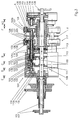
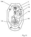
- the transfer head 1 provided the, downstream of the packing head 2 and arranged upstream of a stacking belt conveyor 3, likewise has a housing 102 rotating about a stationary axis 101, on the pair of jaws pivotally mounted about axes of rotation 103 104 are pivotally mounted, rotated 90 ° in relation on the orientation of the pairs of pack jaws 204 of the pack head 2 arranged to hold the individually wrapped candies 205 of the same speed, but with opposite direction of rotation rotating packing head 2 and for delivery are provided on a stacking belt conveyor 3, the with significantly lower conveying speed (approx. 1/3 of the circulating speed of the rotating housing 102 of the transfer head 1 arranges the individually wrapped candies in groups.
- the group-forming stacking belt conveyor 3 For a smooth work is an adjustment the rotational speed of the respective pair of holding jaws with the individually wrapped candy 205 to the conveying speed the group-forming stacking belt conveyor 3 is required, this being by swivel housing 117, i.e. through the around the Rotation axis 103 pivotable articulation of the holding jaw pairs 104 he follows.
- the stacking belt conveyor points to the formation of the groups 3 shows a stacking belt 301 with drivers 302, the stacking belt is guided over a deflection roller 303 and in the area the reception of the candies 205 from the transfer head 1 and Further transport of the candy groups has a counter bearing 304.
- the packing head 2 the one Variety of around the stationary axis 201 on the rotating one Housing 202 has pivotable pack jaws 204, which individually wrapped candies 205 upstream of the stacking belt conveyor 3 arranged transfer head 1 fed to the candies 205 by the holding jaw pairs 104, which are pivotable the housing 102 rotating about the stationary axis 101 are, picks up and leads to the stacking belt conveyor 3, arranged tangentially in the orbit of the candies 205 is.
- the transfer head 1 also has the ability to sweets in their position by 90 ° so that they are not only in the Flat format (as recorded) can be passed on but also for the upright processing of the stacking belt conveyor 3 can be supplied.
- the stacking belt conveyor reveals the rotational speed 3 a significantly lower working speed, preferably at a maximum of about 50% of the working speed the upstream conveyor 1 and 2 is (in general 1/3 of this speed of work), and education Groups A, B of candies 205 are used for further packaging to rods.
- the stacking belt conveyor 3 has the stacking belt 301 with the drivers 302, which are in connection with the counter bearing 304 form storage compartments 305, in which in the present In each case, 3 candies 205 taken side by side can be (Fig. 1) or 5 candies 205 edgewise can be recorded side by side (Fig. 2, Fig. 13-15).
- the stacking belt 301 is over the deflecting rollers 303 continuously circulating.
- a conveyor 5 which is formed here by a feed belt 501 similar to the stack belt 301 by the driver 502 forms individual transport compartments 503 in which the supplied Groups A, B of candies are intermittently removed and e.g. be fed to a bar packer.
- a feed chain 505 as a conveyor and feed path for subsequent packaging of several groups A, B of objects as shown in Figs. 13-15 is.
- a transfer device 4 provided in the sense of cross-funding between the stacking belt conveyor 3 and the further conveying device 5 works and explained in more detail below becomes.
- the transfer head 1 is therefore in a special way to ensure such a function, as follows is explained with reference to FIGS. 2-11.
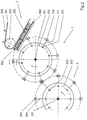
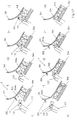
- FIG. 2 A procedural procedure with the transfer rotated by 90 ° Sweets 205 on the stacking belt conveyor 3 are shown in FIG. 2.
- the sweets On the way of receiving the candies 205 from the packing head 2 by the pairs of holding jaws 104 of the transfer head 1 the sweets must be delivered to the stacking belt conveyor 3 205 therefore still 90 ° with simultaneous detection by the Holding jaw pairs 104 are rotated. Preferably done this rotational movement only at the end, i.e. together with one opposing axial movement of the pairs of holding jaws 104 for Release of the candy 205 to the stacking belt 301 of the stacking belt conveyor 3, so that the jaw pairs 104 not just one Subject to axial movement, but at the same time by one Rotational movement of the pairs of holding jaws 104 is superimposed, for rotating the candies 205 in the upright position.
- the design of the transfer head 1 is shown below with the device for rotating the pairs of holding jaws 104 3-11 explained in more detail.
- the transfer head 1 has the central, stationary, however axis 101 rotatable in the circumferential direction, in particular by 180 ° on, which is between a stationary housing 107 and a Bearing plate 108 extends.
- On the stationary axis 101 is rotatably connected to the axis 101, a cam arrangement 109 as part of a motion control device for the holding jaw pairs 104 fixed.
- This cam arrangement 109 consists of a plurality of on the stationary axis 101 cam disks 110, 111, 112, 113 arranged in sequence, 114. They are preferred together with the stationary axis 106 swivels through 180 ° to change the movement pattern for a rotating movement of the individual pairs of holding jaws 104 set up, as will be explained below becomes.
- cam plates 110-114 could also be structurally united or separately via e.g. a common adjusting sleeve, which are rotatably received on the stationary axis 106 is adjustable relative to this by a certain angle his.
- Opposing swivel housing 117 is a pair of holding jaws 104 with the holding jaws 104a, 104b, wherein each holding jaw 104a, 104b is axially movable around the candy 205 pressing on opposing surfaces with frictional engagement and grip by a spring 106 or to release.
- the holding jaws 104a, 104b are also one Holding jaw axis A rotatable around the gripped candy 205 (or another item that is being processed) in a position opposite the receiving position, preferably by 90 ° forward the rotated position (e.g. upright after flat recording).
- the motion control device for each pair of holding jaws 104, the holding jaws 104a, 104b both opposing Axial movement as well as a rotary movement around their Gives the jaw axis A, the cam disks 110, 111, 112, the cams 111 and 112 the axial movement the outer holding jaw 104b (cam disk 111) or the axial movement of the inner holding jaw 104a (cam disc 112) control.
- the control of the axial movement for the inner holding jaw 104a takes place via the control roller of the also by radial Guide body 123 radially guided cam lever 122 on the Sleeve 124, with which the radial guide body 123 rotatably are connected, the sleeve 124 with the inner holding jaw 104a for transmitting the axial movement from the sleeve 124 is directly connected to this holding jaw 104a.
- the cam lever 122 is in insert with its other end 115 of the base housing 102 rotatably mounted.
- pivotable Holding jaw pairs 104 also additionally with a rotary movement to equip the holding jaw axis A to the opposite one Pick-up position from the upstream packing head 1 e.g.
- Each delivery position for candies 205 is rotated by 90 ° Holding jaw 104a, 104b in one piece with a toothed segment 126, 127 provided that in meshing engagement with counter-tooth segments 128, 129, which is once non-rotatable for the outer holding jaw 104b on the shaft 125 or for the inner holding jaw 104a are received on the sleeve 124.
- FIG. 11 The partial sectional view of FIG. 11 (with removed Swivel housing cover) once again illustrates the holding jaws 104a, 104b of the transfer head 1 additionally awarded Degree of freedom and shows the transmission elements for the Transfer of an additional rotary movement, here to the outside Holding jaw 104b about the holding jaw axis A, wherein it can be seen that by an integral connection of the toothed segment 127 with the holding jaw 104b of this by meshing with the counter-toothed segment 129, a rotary movement about the holding jaw axis A can be awarded when the shaft is twisted 125, with which the counter-tooth segment 129 is firmly connected.
- the gap is a holding finger for each swivel housing 117 137 in a central radial plane B between the two holding jaws 104a, 104b, practically in plant or immediately adjacent provided for the respective article, here candy 205, the reliable support and handover of the candy 205 from the transfer head 1 to the successor device, here the stacking belt 301 of the stacking belt conveyor 3 is supported.
- FIG. 11a and 11b schematically the transfer of the individually wrapped candies 205 from the transfer head 1 for one Holding jaw pair shown schematically, in Fig. 11a for the formation of groups for upright packaging under rotation the holding jaws 104a, 104b (as described above) and in Fig. 11b for the formation of groups in a flat pack (no additional rotation of the holding jaws 104a, 104b), whereby especially for Fig. 11a it is clear that the rotary movement the holding jaws 104a, 104b about the holding jaw axis A in Area of transfer to the stacking belt conveyor 3, i.e. under Superimposition of the pivoting movement that the holding jaws 104a, Execute 104b with the swivel housing 117.
- the counter bearing 304 has an insertion slope 304a and the holding finger 137 may be used to support the handover process ready.
- Group A, B is then moved by driver 302 along the counter holder in a packing compartment 305 thus formed promoted away.
- the transfer device 4 has a transverse pushing device 401 with a pusher 402, the width of which in the conveying direction of the stacking belt 301 approx. the total width of a group A, B of candies corresponds to 205, i.e. is slightly less than that Distance between two subsequent drivers 302 of the stacking belt 301, so that the pusher 402 in a between the Carrier 302 and the counter bearing 304 formed packing compartment 305 immerse and collectively group A, B of candies 205 in Can convey out the transverse direction from the stack conveyor 3 (see also Figs. 13 and 15).
- the pusher 402 a correspondingly combined, consisting of exhaust longitudinal and transverse movement composite control movement, preferably in the area before or after immersion with Vertical motion control components are combined to create a to obtain favorable movement behavior of the pusher 402.
- the control curve for the pusher 402 is 403 indicated schematically. The movement of the pusher 402 in The broken line 403a in FIG Fig. 13.
- the drive device for the pusher 402 is not shown in detail, is preferably the Pusher with a hydraulic between a working and a non-working position switchable, preferably hydraulic controlled knee joint controlled so that the drive of the pusher depending on an observation of the Grouping of the candy pieces or a quality observation the individual packaging of the candies 205 are shut down can. Due to the continuous conveying principle of the stacking belt conveyor 3 would be considered faulty or so incompletely recognized groups of candies without actuation of the pusher 402 simply to the rear in the conveying direction of the stacking belt 301 (arrow X in FIG.
- the pusher 402 works on an intermediate plate 404, which correspond to the circulating speed of the stacking belt 301 also horizontally in the transfer area, i.e. in the work area of the expeller 402 at one of the speeds of the stack belt 301 corresponding speed horizontally is moved (the withdrawal movement to the starting position takes place more quickly).
- a drive device for the intermediate plate 404 is in the schematic representations according to FIG. 13 and 15 at 405.
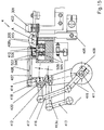
- the intermediate plate 404 works to transfer the group Candy 205 together on the feed belt 501 or the feed chain 505 (Fig. 15) together a transverse pull device 406, the for the defined delivery of each group A, B of candies 205 has a counterholder 407 and a gripper part 408 which by a common drive lever 409 (see FIG. 15) in its Movement can be controlled and interact with each other as in 15 is shown to form a transport compartment 410 in which the respective group A, B is located on the intermediate plate 404, to then be pulled down from this and onto the feed belt 501 or the feed chain 505 to be pulled as this will be explained with reference to FIGS. 14 and 15.
- the transport compartment 410 communicated through the counter holder 407 with the gripper part 408 on the intermediate plate 404 and formed downstream of it, can also be designed larger so that e.g. two groups of candies 205 from the Stacking belt conveyor 3 in a row on the intermediate plate 404 are pushed out by the pusher 402 and only then the gripper part 408 behind the last one pushed out Group intervenes and the two following groups together conveyed onto the feed belt 501 or the feed chain 505 and then intermittently with this traction device be promoted.
- the counterholder 407 essentially performs a horizontal movement between the feed belt 501 or the feed chain 505 (Fig. 15) and the intermediate plate 404, controlled by the common drive lever designed as a rocker arm 409, the fixed with a hollow shaft, not shown here is connected and via a swivel 412 a counter-holder rocker 413 moves, with a control lever 413a of the counter-holder rocker 413 a holder 414 is connected, which in turn firmly holds the counter-holder 407. Furthermore, the drive lever 409 via a swivel 420 motion-transmitting connected to a holder 418 of the gripper part 408, the one additional gripping stroke movement via a control lever 419 and a control pad 416 is awarded.
- the Feed chain 505 for intermittently feeding the groups A, B points to a bar packer (not shown here) connected to the individual chain links in the usual way
- Carrier 506 the transport compartments with carrier plates for groups A, B of candies 205 on the supply chain 505, which is accommodated in a housing 509, the top plate 508 a transport slideway for the groups A, B forms.
- Fixed side guides for the feed conveyor 5 are designated in FIG. 13 by 510 and 511.
- Figure 14 illustrates in steps a - c in schematic Top views each show a transfer process from the continuous Stacking belt conveyor 3 to the intermittent conveyor Chain conveyor 5, wherein in Fig. 14a (rest position) a group A is on the stacking belt 301 of the stacking belt conveyor 3 is in the position between two drivers 302, in which the pusher 402 attack group A and the group can pass onto the intermediate plate 404. In this Position is also an already transferred one Group B in the transport compartment between counterholder 407 and Gripper part 408 between two driver plates 507 of the chain conveyor 5.
- FIG. 14b the feed chain 505 is advanced one step and the counterholder 407 and the gripper part 408 reach through an empty transport area between two Driver plates 507 through towards the intermediate plate 404.
- FIG. 14c it is shown how the pusher 402 the group A on the intermediate plate 404 and in this here first transport compartment 410 formed by the counter-holder 407 inserts. Then the gripper part 408 with the Gripper nose 408a in a lifting gripping movement over group A reach away and from the opposite side with the counterholder 407 onto the top plate 508 of the move the chain conveyor having the feed chain 505. The gripper part 408 is covered in FIG. 14c (since covered by the counter-holder 407) not shown.
- the pusher 402 is not operated and thanks the continuous promotion of the stacking belt conveyor 3 run the defective products simply in the conveying direction of the stacking belt 301 from the stacking belt conveyor 3.
Description
Die Erfindung betrifft ein Verfahren zur Weitergabe von Gegenständen, bei dem die Gegenstände einzeln zugeführt und in Gruppen abgeführt werden. Die Erfindung betrifft ferner eine Vorrichtung mit den Merkmalen des Oberbegriffs von Patentanspruch 11.The invention relates to a method for the transfer of objects, in which the items are fed individually and removed in groups. The invention further relates to a device with the features of the preamble of claim 11.
Für die Verpackung kleinstückiger Gegenstände, z.B. von Süßwaren wie Bonbons, (z.B. Weich- oder Hartkaramellen) ist es bekannt, z.B. zum Einzelverpacken der Gegenstände, diese auf der Grundlage eines Rotations- Transportprinzipes durch die Verpackungsmaschine zu bewegen. Hierbei werden z.B. von einem Massestrang abgetrennte Bonbons zunächst von einem Greiferrad ergriffen und unter Rotation desselben an ein mit gleichem Wirkumfang versehenes Übergaberad übergeben, das seinerseits unter Geschwindigkeitsausgleich die Gegenstände an ein Einwickelrad weitergibt (WO-A-93/10005).For packaging small items, e.g. of sweets like candy, (e.g. soft or hard caramels) it is known e.g. for individual packaging of the objects, these on the basis of a rotation transport principle to move through the packaging machine. Here, e.g. of a Mass strand of separated sweets first gripped by a gripper wheel and while rotating it to a transfer wheel provided with the same effective range passed, which in turn under speed compensation of the objects passes on to a wrapping wheel (WO-A-93/10005).
Derartige, auf dem "Rotationsprinzip" der Übergabeorgane aufgebaute Verpackungsmaschinen, insbesondere Bonbonsverpackungsmaschinen, können im Hochleistungsbereich mit Verpackungsgeschwindigkeiten von bis zu ca. 1.500 Stück pro Minute arbeiten und sind außerordentlich effizient. Schwierigkeiten bereitet bei derartigen Hochleistungs-Verpackungsmaschinen die gleichermaßen wirtschaftliche weitere Prozeßgestaltung, z.B. zur Bildung von zu Stangen abgepackten Gegenständen.Such packaging machines based on the "rotation principle" of the transfer elements, in particular candy packaging machines, can High-performance area with packaging speeds of up to approx. 1,500 Work pieces per minute and are extremely efficient. Creates difficulties the same with such high-performance packaging machines economical further process design, e.g. to form packaged into bars Objects.
Ein Verfahren und eine Vorrichtung der eingangs genannten Art sind aus der DE-A1-23 35 026 bekannt. Jedoch werden dort mit Hilfe eines Greiferpaares mehrere Einzelpackungen auf einmal gegriffen und gebündelt, im gebündelten Zustand verpackt und anschließend in auf einem Förderband transportierte Umverpackungen abgelegt.A method and a device of the type mentioned at the outset are from DE-A1-23 35 026 known. However, there are several with the help of a pair of grippers Single packs gripped and bundled at once, in bundled condition packed and then in outer packaging transported on a conveyor belt filed.
Ein weiteres Verpackungsverfahren, bei dem Gegenstände unmittelbar aufeinanderfolgend auf ein Förderband abgelegt werden, sowie eine entsprechende Vorrichtung hierfür, ist aus der EP-A1-0 538 762 bekannt. Another packaging process in which items are in immediate succession placed on a conveyor belt, as well as a corresponding device for this is known from EP-A1-0 538 762.
Der Erfindung liegt daher die Aufgabe zugrunde, ein Verfahren und eine Vorrichtung der eingangs genannten Art anzugeben, die es gestatten, Gegenstände, ggf. auch nach vorheriger Einzelverpackung, mit hoher Arbeitsgeschwindigkeit zu Gruppen zusammenzuordnen und stapelbar zu machen, ggf. zu einer Erst- oder Weiterverpackung zu Stangen.The invention is therefore based on the object of a method and a device of the type mentioned at the beginning, which allow objects, possibly even after previous individual packaging, at high speed Organize groups and make them stackable, possibly for a first or Further packaging to bars.
Im Hinblick auf das Verfahren wird die vorgenannte Aufgabe erfindungsgemäß gelöst durch ein die Merkmale des Patentanspruchs 1 umfassendes Verfahren. Das erfindungsgemäße Verfahren hat den Vorteil, daß es auf der Grundlage der im wesentlichen auf Kreissegmentabschnitten erfolgenden Förderung der Gegenstände, wie z.B. Bonbons, durch eine Verpackungsmaschine möglich ist, unter Beibehaltung dieses den Hochleistungsbetrieb ermöglichenden Arbeitsweise auch einzelne Gegenstände zu Gruppen zusammen zu ordnen, zur Vorbereitung einer Stangenbildung, in der die Gegenstände einzeln aneinanderliegend, verpackt oder unverpackt, enthalten sind.With regard to the method, the aforementioned object is achieved according to the invention solved by a method comprising the features of claim 1. The inventive method has the advantage that it is based on the promotion of the objects mainly on circular segment sections, such as. Candy, possible through a packaging machine, under Maintaining this way of working, which enables high-performance operation arrange individual objects into groups to prepare one Rod formation, in which the objects are packed one after the other or unwrapped.
Nach einer bevorzugten Ausführungsform der Erfindung sind die an dem rotierenden Träger angeordneten Haltebacken für die Gegenstände um eine im wesentlichen parallel zur Drehachse des Trägers verlaufende Achse schwenkbar, wobei diese relative Schwenkbewegung der Haltebackenpaare zur Grund-Rotationsbewegung des Trägers in vorteilhafter Weise eine Geschwindigkeitsanpassung zwischen dem Träger und dem nachgeordneten Stapelbandförderer erlaubt, wobei das Geschwindigkeitsverhältnis in weitem Rahmen variabel ist. According to a preferred embodiment of the invention, those on the rotating Carrier arranged holding jaws for the objects around a substantially Axis extending parallel to the axis of rotation of the carrier, wherein this relative pivoting movement of the pairs of holding jaws to the basic rotational movement of the carrier in an advantageous manner a speed adjustment allowed between the carrier and the downstream stacking belt conveyor, wherein the speed ratio is widely variable.
Vorzugsweise ist die Umlaufgeschwindigkeit des Trägers größer als eine Fördergeschwindigkeit, insbesondere Umlaufgeschwindigkeit, eines Stapelbandes des Stapelbandförderers.The rotational speed of the carrier is preferably greater than a conveying speed, in particular circulation speed, a stacking belt of the Stacking belt conveyor.
Nach einer weiteren bevorzugten Ausgestaltung des erfindungsgemäßen Verfahrens wird jede Gruppe von in dem Stapelbandförderer gruppierten Gegenständen durch eine im wesentlichen rechtwinklig zur Förderrichtung des Stapelbandförderers arbeitende Ausstoßvorrichtung in einem Abgabebereich aus dem Stapelbandförderer abgegeben, wobei vorzugsweise ein Druckförderprinzip angewandt wird. Dabei wird vorzugsweise die Gruppe von Gegenständen auf eine im wesentlichen parallel zur Förderrichtung des Stapelbandförderers bewegbare Zwischenlagervorrichtung abgegeben, von der ihrerseits unter Anwendung eines Zugförderprinzips die Gegenstände gemeinsam von der Zwischenlagervorrichtung auf ein Zuführungsorgan einer Verarbeitungsmaschine, insbesondere Verpackungsmaschine, wie z.B. einem Stangenpacker gefördert werden.According to a further preferred embodiment of the method according to the invention becomes each group of objects grouped in the stacking belt conveyor by a substantially perpendicular to the conveying direction of the stacking belt conveyor working ejection device in a delivery area from the stacking belt conveyor given, preferably a pressure delivery principle is applied. The group of objects is preferably essentially one Intermediate storage device movable parallel to the conveying direction of the stacking belt conveyor delivered, of which in turn using a train promotion principle the objects together from the intermediate storage device to a feed member a processing machine, especially a packaging machine, such as. be supported by a pole packer.
Weitere, bevorzugte Ausgestaltungen des erfindungsgemäßen Verfahrens, insbesondere in bezug auf die Aufnahme der Gegenstände durch die an dem Träger schwenkbar gelagerten Haltebacken sowie auf die Abstimmung der Fördergeschwindigkeiten der einzelnen Transportorgane sind in den übrigen Unteransprüchen dargelegt.Further preferred configurations of the method according to the invention, especially with regard to the inclusion of the objects by those on the carrier swiveling holding jaws and on the coordination of the conveyor speeds of the individual transport organs are in the remaining subclaims spelled out.
Hinsichtlich der Vorrichtung wird die vorgenannte Aufgabe durch eine Vorrichtung mit den Merkmalen des Patentanspruches 11 gelöst. With regard to the device, the aforementioned task is performed by a device solved with the features of claim 11.
Die vorgenannte Vorrichtung ist besonders vorteilhaft, da sie unter Beibehaltung einer Einzelbehandlung von Gegenständen in einer Verpackungsmaschine und unter Beibehaltung des Prinzips einer "rotierenden" Weitergabe die Möglichkeit schafft, eine Mehrzahl von Gegenständen mit außerordentlich hohen Arbeitsgeschwindigkeiten in Gruppen zusammenzuordnen und einer weiteren Behandlung, z.B. zur Bildung von Stangen aus einer Vielzahl einzelner, vorgruppierter Gegenstände, verpackt oder unverpackt, zu unterziehen.The aforementioned device is particularly advantageous since it is retained an individual treatment of objects in a packaging machine and while maintaining the principle of "rotating" transmission creates a large number of objects with extremely high working speeds to put them in groups and a further treatment, e.g. to form rods from a large number of individual, pre-grouped objects, packaged or unwrapped to undergo.
Nach einer bevorzugten Weiterbildung der erfindungsgemäßen Vorrichtung weist der Stapelbandförderer ein umlaufendes Stapelband mit einer Mehrzahl von Vorsprüngen auf, zur Bildung der Packfächer mit einem stationär gegenüberliegend zwischen einem Aufnahmeabschnitt des Stapelbandförderers und einem Abgabeabschnitt desselben angeordneten Gegenlager. Durch eine Schienenausbildung des Gegenlagers, ggf. auch einer Mehrzahl beabstandeter Schienen durch die auch Weiterförderorgane von unten her eingreifen könnten (in Abhängigkeit von der Konfiguration des Stapelbandförderers) ist es möglich, die Gegenstände gruppenweise mit geringen Reibungsbeiwerten weiterzutransportieren, so daß insgesamt eine schonende Behandlung der Gegenstände, die vorzugsweise bereits einzelverpackt sind, ermöglicht ist.According to a preferred development of the device according to the invention the stacking belt conveyor is a rotating stacking belt with a plurality of projections on, to form the packing compartments with a stationary opposite between a receiving section of the stacking belt conveyor and a delivery section the same arranged counter bearing. Through a rail training the counter bearing, possibly also a plurality of spaced rails through the funding bodies could also intervene from below (depending on the configuration of the stacking belt conveyor) it is possible to move the objects to be transported in groups with low coefficients of friction so that overall a gentle treatment of the objects, preferably already are individually packed, is possible.
Für eine, die Beibehaltung einer hohen Arbeitsgeschwindigkeit (unter Berücksichtigung des erforderlichen Geschwindigkeitsgefälles zwischen dem Träger und dem Stapelbandförderer) ist es vorteilhaft, daß die Bildung der Packfächer im wesentlichen tangential zu dem Bewegungsweg der Haltebackenpaare an dem Träger erfolgt. For one, keeping a high working speed (taking into account the required speed difference between the carrier and the stacking belt conveyor) it is advantageous that the formation of the packing compartments essentially tangential to the path of movement of the pairs of holding jaws on the carrier he follows.
Nach noch einer bevorzugten Ausführungsform der Erfindung weisen die Haltebackenpaare des Trägers ihrerseits bewegliche Haltebacken auf, zwischen denen der betreffende Gegenstand jeweils direkt aufgenommen und abgestützt ist, wobei die Haltebacken separat von zugehörigen, die Haltebacken lagernden Schwenkgehäusen beweglich und insbesondere gegenüber diesen verdrehbar sind, so daß es möglich ist, die von den Haltebacken erfaßten Gegenstände auf dem Wege zwischen dem Aufnahmebereich des Trägers und dem Abgabebereich desselben an den Stapelbandförderer z.B. um 90° zu drehen. Hierdurch können z.B. prismatische Gegenstände in flacher Orientierung zunächst durch die Haltebacken erfaßt, jedoch in einer Hochkant-Orientierung zur Gruppenbildung und Abstapelung an den Stapelbandförderer weitergegeben werden (oder vice versa).According to a preferred embodiment of the invention the pairs of holding jaws of the carrier, in turn, move Holding jaws between which the object in question each is directly received and supported, the holding jaws separate from the associated ones, which hold the holding jaws Swivel housings movable and in particular in relation to them are rotatable so that it is possible by the holding jaws detected objects on the way between the recording area of the carrier and the delivery area thereof to the Stacking belt conveyor e.g. turn by 90 °. This can e.g. prismatic objects in a flat orientation initially gripped by the holding jaws, but in an upright orientation for group formation and stacking at the Stacking belt conveyors are passed on (or vice versa).
Nach noch eine weiteren, bevorzugten Ausgestaltung der erfindungsgemäßen Vorrichtung ist in einem Abgabebereich des Stapelbandförderers eine Querschubvorrichtung als Ausstoßvorrichtung zum Ausschieben der gruppenweise geförderten Gegenstände aus den Packfächern des Stapelbandförderers vorgesehen.According to yet another preferred embodiment of the invention The device is in a delivery area of the stacking belt conveyor a transverse thrust device as an ejection device for pushing out the objects conveyed in groups provided from the packing compartments of the stacking belt conveyor.
Durch diese Ausstoßvorrichtung erfolgt eine gruppenweise Querverlagerung der Gegenstände zur Weiterverpackung. In Abhängigkeit von einem Steuersignal an die Querschubvorrichtung kann diese auch bei Feststellung nicht-qualitätsgrechten Gegenständen stillgesetzt werden, so daß eine als unvollständig oder als zumindest teilweise qualitativ unzureichend erkannte Stufe in Förderrichtung des Stapelbandförderers abgefördert wird.This ejection device is used in groups Transverse displacement of the objects for further packaging. Dependent on from a control signal to the cross thruster can do this even if it detects non-quality objects be stopped so that one is incomplete or recognized as at least partially qualitatively insufficient Stage in the conveying direction of the stacking belt conveyor becomes.
Vorzugsweise ist in Verbindung mit der Schiebervorrichtung eine Zwischenlagervorrichtung, insbesondere Zwischenplatte, vorgesehen, die parallel zur Förderrichtung, die das Stapelband im Ausgabebereich des Stapelbandförderers einnimmt, bewegbar ist. Is preferably in connection with the slide device an intermediate storage device, in particular an intermediate plate, provided that is parallel to the conveying direction, the stacking belt occupies in the output area of the stacking belt conveyor, movable is.
Zur Verwendung mit einem Stangenpacker kann vorzugsweise stromab der Zwischenlagervorrichtung, insbesondere Zwischenplatte, ein Zuführband zur gruppenweisen Zuführung der Gegenstände zu einer Verpackungsmaschine, insbesondere einen Stangenpacker vorgesehen und eine Übergabevorrichtung zum gleichzeitigen Zufördern einer oder einer Mehrzahl von in der Zwischenlagervorrichtung befindlichen Gruppen von Gegenständen zu dem Zuführband vorgesehen sein.Can preferably be used with a bar packer downstream of the intermediate storage device, in particular intermediate plate, a feed belt for feeding the objects in groups to a packaging machine, especially a bar packer provided and a transfer device for simultaneous Feeding one or a plurality of in the intermediate storage device groups of objects be provided to the feed belt.
Vorzugsweise ist der rotierende Träger ein zwischen einem rotierenden Packkopf und dem Stapelbandförderer angeordneter Übergabekopf, der ein um eine stationäre Achse rotierendes Gehäuse, an dem schwenkbar eine Mehrzahl von Haltebackenpaare aufgenommen ist, aufweist, wobei eine Schwenksteuerung der Haltebackenpaare sowie eine separate Drehbewegung der Haltebacken durch eine stationäre, gemeinsam mit der Achse verstellbare Kurvenscheibenanordnung erfolgt.The rotating carrier is preferably one between a rotating one Packing head and the stacking belt conveyor arranged Transfer head, which rotates around a stationary axis Housing on which a plurality of pairs of holding jaws can be pivoted is included, with a swivel control of the Pairs of holding jaws and a separate rotary movement of the holding jaws through a stationary, adjustable jointly with the axis Cam disc arrangement takes place.
Weitere, bevorzugte Ausgestaltungen der erfindungsgemäßen Vorrichtung sind in den übrigen Unteransprüchen dargelegt.Further preferred configurations of the invention Device are set out in the remaining subclaims.
Die Erfindung wird nachstehend anhand eines Ausführungsbeispieles und zugehöriger Zeichnungen näher erläutert. In diesen zeigen:
- Fig. 1
- eine Vorrichtung zur Weitergabe von Gegenständen nach einem Ausführungsbeispiel der Erfindung, wobei einzelne Gegenstände, hier Bonbons, zunächst einzelverpackt, anschließend eine Gruppenbildung der einzelverpackten Bonbons erfolgt und schließlich die Gruppen einem Zuführungsförderer für einen Stangenpacker zugeführt werden und für Flachpackung,
- Fig. 2
- eine schematische Darstellung der Weitergabevorrichtung nach Fig. 1 im Bereich einer Zuförderung der einzelverpackten Gegenstände zu einem Stapelbandförderer über einen Übergabekopf von einem Packkopf unter 90°-Drehung der Gegenstände durch den Übergabekopf, abweichend von dem Ausführungsbeispiel nach Fig. 1 (Hochkantpackung),
- Fig. 3
- einen Längsschnitt durch einen Übergabekopf in einer Bonbon-Verpackungsmaschine,
- Fig. 4
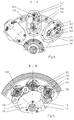
- eine Teilschnitt-Darstellung entlang einer Linie A-A nach Fig.1,
- Fig. 5
- eine Teilschnitt-Darstellung entlang einer Linie B-B nach Fig. 1,
- Fig. 6
- eine Teilschnitt-Darstellung entlang einer Linie C-C nach Fig.1,
- Fig. 7
- eine Teilschnitt-Darstellung entlang einer Linie D-D nach Fig. 1,
- Fig. 8
- eine Teilschnitt-Darstellung entlang einer Linie E-E nach Fig.1,
- Fig. 9
- eine Teilschnitt-Darstellung entlang einer Linie F-F nach Fig. 1,
- Fig. 10
- eine Teilschnitt-Darstellung entlang einer Linie G-G nach Fig.1,
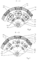
- Fig. 11
- eine Ansicht ähnlich derjenigen in Fig. 2 für eine einzelne Haltebacke (äußere Axialansicht), und
- Fig. 12
- eine schematische Darstellung für den Bewegungsablauf bei der Bildung der Gruppierung an der Übergabestelle zwischen Übergabekopf und Stapelbandförderer für die Herstellung von Hochkantpackungen (Fig. 12a) und Flachpackungen (Fig. 12b),
- Fig. 13
- eine Draufsicht auf eine Übergabevorrichtung für die Weitergabevorrichtung nach Fig. 1,
- Fig. 14a - 14c
- eine Darstellung der Phasen einer Ausförderung einer Gruppe von Gegenständen aus einem Stapelbandförderer nach einer Ausführungsform gemäß Fig. 2 (Hochkantpackung) bzw. Fig. 12a zu einer Weiterfördereinrichtung, und
- Fig. 15
- eine Querschnittsdarstellung der Übergabevorrichtung nach Fig. 14 in schematischer Darstellung.
- Fig. 1
- a device for the transfer of objects according to an embodiment of the invention, wherein individual objects, here candies, are initially individually packaged, then the individually packaged candies are formed into groups and finally the groups are fed to a feed conveyor for a bar packer and for flat packs,
- Fig. 2
- 1 in the area of feeding the individually packaged objects to a stacking belt conveyor via a transfer head from a packing head with 90 ° rotation of the objects by the transfer head, in deviation from the exemplary embodiment according to FIG. 1 (upright package),
- Fig. 3
- a longitudinal section through a transfer head in a candy packaging machine,
- Fig. 4
- 2 shows a partial sectional illustration along a line AA according to FIG. 1,
- Fig. 5
- 2 shows a partial sectional illustration along a line BB according to FIG. 1,
- Fig. 6
- 2 shows a partial sectional illustration along a line CC according to FIG. 1,
- Fig. 7
- 2 shows a partial sectional illustration along a line DD according to FIG. 1,
- Fig. 8
- 2 shows a partial section along a line EE according to FIG. 1,
- Fig. 9
- 2 shows a partial sectional illustration along a line FF according to FIG. 1,
- Fig. 10
- 2 shows a partial section along a line GG according to FIG. 1,
- Fig. 11
- a view similar to that in Fig. 2 for a single holding jaw (external axial view), and
- Fig. 12
- 1 shows a schematic illustration of the sequence of movements when forming the grouping at the transfer point between the transfer head and the stacking belt conveyor for the production of upright packs (FIG. 12a) and flat packs (FIG. 12b),
- Fig. 13
- 2 shows a plan view of a transfer device for the transfer device according to FIG. 1,
- 14a-14c
- a representation of the phases of a group of objects being conveyed out of a stacking belt conveyor according to an embodiment according to FIG. 2 (upright packaging) or FIG. 12a to a further conveying device, and
- Fig. 15
- a cross-sectional view of the transfer device of FIG. 14 in a schematic representation.
Ein bevorzugtes Ausführungsbeispiel des Verfahrens und der Vorrichtung zur Weitergabe von Gegenständen wird nachfolgend erläutert.A preferred embodiment of the method and the device for the transfer of objects is explained below.
Das Ausführungsbeispiel, das die Verpackung von Bonbons 205
von prismatischer Geometrie, z.B. von Weich- oder Hartkaramellen
darstellt, insbesondere unter Vorbereitung der einzelverpackten
Bonbons 205 für die Zuführung zu einem - hier
nicht dargestellten - Stangenpacker, ist selbstverständlich
nicht auf die Handhabung dieser Art von Gegenständen beschränkt,
sondern kann für eine Vielzahl anderer, insbesondere
kleinstückiger Gegenstände, die verpackt werden sollen und
die insbesondere entweder bereits einzeln vorverpackt oder
auch unverpackt zu Gruppen versammelt und insbesondere zu
Stangen verpackt werden sollen, Anwendung finden. Darüberhinaus
können einzelne Elemente der Gesamtvorrichtung, wie z.B.
ein Übergabekopf, auch in anderen Zusammenhängen und Maschinenverknüpfungen
eingesetzt werden.The embodiment that the packaging of
In derartigen Verpackungsmaschinen können einzelne, z.B. von
einem kontinuierlichen Massestrang abgetrennte Bonbonstücke
nach Aufnahme und Zuförderung über ein hier nicht dargestelltes
Greiferad und Übergaberad (wie dies aus der WO 93/25440
bekannt ist), zu einem umlaufenden Packkopf 2 gefördert, der
hinsichtlich seiner Bewegungsmechanik mit einem ähnlichen
Grundaufbau wie der Übergabekopf 1 versehen ein um eine stationäre
Achse 201 rotierendes Gehäuse 202 aufweist, an dem um
Drehachsen 203 schwenkbar jeweils ein Packbackenpaar 204 gelagert
ist, das das Bonbonstück aufnimmt und unter Zuführung
eines Packmaterialabschnittes das Bonbonstück zu dem einzelverpackten
Bonbon 205 verpackt, ohne daß dies hier im einzelnen
dargestellt wäre.In such packaging machines individual, e.g. of
a continuous mass strand of cut candy pieces
after admission and funding via a not shown here
Gripper wheel and transfer wheel (as this from WO 93/25440
is known), promoted to a
Vielfach besteht der Wunsch, derartige, einzelverpackte
Kleinartikel, wie die Bonbons 205 anschließend in Stangen abzupacken,
wie dies auch für Weichkaramellen oder andere Süßigkeiten
(z.B. Kaugummis) bekannt ist. Hierzu ist es erforderlich,
die Einzelstücke der einzeln verpackten Bonbons 205
zu Gruppen zusamnmenzuordnen, um sie sodann einem (hier ebenfalls
hier nicht dargestellten) Stangenpacker zuzuführen.
Hierzu ist der Übergabekopf 1 nach dem vorliegenden Ausführungsbeispiel
vorgesehen, der, stromab des Packkopfes 2 und
stromauf eines Stapelbandförderers 3 angeordnet, ebenfalls
ein um eine stationäre Achse 101 rotierendes Gehäuse 102 aufweist,
an dem um Drehachsen 103 schwenkbar gelagert Haltebackenpaare
104 schwenkbar gelagert sind, die 90° gedreht in Bezug
auf die Orientierung der Packbackenpaare 204 des Packkopfes
2 angeordnet zur Aufnahme der einzelverpackten Bonbons
205 von dem mit gleicher Umlaufgeschwindigkeit, jedoch mit
entgegengesetztem Drehsinn umlaufenden Packkopf 2 und zur Abgabe
an einen Stapelbandförderer 3 vorgesehen sind, der mit
wesentlich geringerer Fördergeschwindgkeit (ca. 1/3 der Umlaufgeschwindigkeit
des rotierenden Gehäuses 102 des Übergabekopfes
1 die einzelverpackten Bonbons gruppenweise zusammenordnet.
Für ein reibungsloses Arbeiten ist eine Anpassung
der Umlaufgeschwindigkeit des jeweiligen Haltebackenpaares
mit dem einzelverpackten Bonbon 205 an die Fördergeschwindigkeit
des gruppenbildenden Stapelbandförderers 3 erforderlich,
wobei dies durch Schwenkgehäuse 117, d.h. durch die um die
Drehachse 103 schwenkbare Anlenkung der Haltebackenpaare 104
erfolgt. Zur Bildung der Gruppen weist der Stapelbandförderer
3 ein Stapelband 301 mit Mitnehmern 302 auf, wobei das Stapelband
über eine Umlenkwalze 303 geführt wird und im Bereich
der Aufnahme der Bonbons 205 von dem Übergabekopf 1 sowie zum
Weitertransport der Bonbon-Gruppen ein Gegenlager 304 aufweist.There is often a desire for such individually packaged
Small items, like packing the
Wie Fig. 1 zeigt, werden somit von dem Packkopf 2, der eine
Viehlzahl von um die stationäre Achse 201 an dem rotierenden
Gehäuse 202 schwenkbarer Packbackenpaare 204 aufweist, die
einzelverpackten Bonbons 205 dem stromauf des Stapelbandförderers
3 angeordneten Übergabekopf 1 zugeführt, der die Bonbons
205 durch die Haltebackenpaare 104, die schwenkbar an
dem um die stationäre Achse 101 rotierenden Gehäuse 102 gelagert
sind, aufnimmt und zu dem Stapelbandförderer 3 führt,
der tangential in der Umlaufbahn der Bonbons 205 angeordnet
ist.As shown in Fig. 1, the packing
Der Übergabekopf 1 besitzt zugleich die Fähigkeit, die Bonbons
in ihrer Lage um 90° zu drehen, so daß sie nicht nur im
Flachformat (wie aufgenommen) weitergegeben werden können,
sondern auch für eine Hochkantweiterverarbeitung dem Stapelbandförderer
3 zugeführt werden können.The transfer head 1 also has the ability to sweets
in their position by 90 ° so that they are not only in the
Flat format (as recorded) can be passed on
but also for the upright processing of the stacking
Während der Übergabekopf 1 und der Packkopf 2 im wesentlichen
mit einer gleichen z.B. 1.500 Bonbons pro Minute behandelnden
Rotationsgeschwindigkeit umlaufen, weist der Stapelbandförderer
3 eine deutliche geringere Arbeitsgeschwindigkeit auf,
die vorzugsweise bei maximal ca. 50% der Arbeitsgeschwindigkeit
der vorgeschalteten Förderer 1 und 2 liegt (im allgemeinen
1/3 dieser Arbeitsgeschwindigkeit beträgt), und der Bildung
Gruppen A, B von Bonbons 205 dient, zur Weiterverpackung
zu Stangen.During the transfer head 1 and the
Zu diesem Zweck weist der Stapelbandförderer 3 das Stapelband
301 mit den Mitnehmern 302 auf, die in Verbindung mit dem Gegenlager
304 Packfächer 305 bilden, in denen im vorliegenden
Fall jeweils 3 Bonbons 205 nebeneinanderliegend aufgenommen
werden können (Fig. 1) oder jeweils 5 Bonbons 205 hochkant
nebeneinanderliegend aufgenommen werden können (Fig. 2, Fig.
13-15). Das Stapelband 301 wird über die Umlenkwalzen 303
kontinuierlich umlaufend geführt.For this purpose, the stacking
Zur Bereitstellung der zu Gruppen zusammengefaßten Bonbons
205, die bereits einzelverpackt sind, an eine Weiterfördereinrichtung
5, die hier durch ein Zuführband 501 gebildet
wird, das ähnlich wie das Stapelband 301 durch Mitnehmer 502
einzelne Transportfächer 503 bildet, in denen die zugeführten
Gruppen A, B von Bonbons intermittierend abgefördert und z.B.
einem Stangenpacker zugeführt werden.To provide the candies grouped together
205, which are already individually packaged, to a
In der schematischen Darstellung nach Fig. 1 ist die Weiterfördereinrichtung
5 als Zuführband 501, umgelenkt um die Umlenkwalze
504, ausgeführt. Im Hinblick auf Stangenpacker wird
vielfach jedoch bevorzugt, die Gruppen A, B von Bonbons 205
einer Zuführkette 505 als Weiterfördereinrichtung und Zuführbahn
für eine anschließende Verpackung mehrerer Gruppen A, B
von Gegenständen zuzuführen, wie dies in Fig. 13 - 15 dargestellt
ist.1 is the further conveying
Zur gruppenweisen Bereitstellung der Bonbons 205 (in Fig. 1
Dreiergruppen, in Fig. 2 sowie Fig. 13 - 15 in Fünfergruppen
hochkant) und zur Weiterförderung zu dem Zuführband 501 (Fig.
1) bzw. der Zuführkette 505 (Fig. 13 - 15) ist eine Übergabevorrichtung
4 vorgesehen, die im Sinne einer Querförderung
zwischen dem Stapelbandförderer 3 und der Weiterfördereinrichtung
5 arbeitet und die weiter unten genauer erläutert
wird.To provide the
In dem Ausführungsbeispiel gem. Fig. 1 werden die Bonbons 205
zur Herstellung von Flachpackungen in der gleichen Orientierung
wie von dem Packkopf 2 aufgenommen, d.h. ohne Rotation
an den Stapelbandförderer 3 übergeben, wie dies auch bei der
diesem Ausführungsbeispiel entsprechenden Darstellung des
Übergabevorganges gem. Fig. 12b der Fall ist. In the embodiment according to 1, the
In vielen Fällen ist es jedoch wünschenswert, die Weiterverpackung mit um ca. 90° gedrehten Artikeln, bei prismatischen Gegenständen, z.B. im Hochkantformat zur Bildung von Hochkantpackungen (Stangen) oder für eine sonstige Weiterverarbeitung, vorzunehmen (s. Fig. 12a).In many cases, however, it is desirable to continue packing with articles rotated by approx. 90 °, with prismatic ones Objects, e.g. in portrait format for the formation of portrait packages (Bars) or for other processing, to make (see Fig. 12a).
Der Übergabekopf 1 ist daher in spezieller Weise zur Gewährleistung einer solchen Funktion ausgebildet, wie dies nachstehend anhand der Fig. 2 - 11 erläutert ist.The transfer head 1 is therefore in a special way to ensure such a function, as follows is explained with reference to FIGS. 2-11.
Eine Verfahrensführung mit um 90° gedrehter Weitergabe der
Bonbons 205 an den Stapelbandförderer 3 zeigt Fig. 2.A procedural procedure with the transfer rotated by 90 °
Eine wesentliche Voraussetzung für die Gruppenbildung der
einzelverpackten Bonbons 205 am Stapelbandförderer 3 ist daher
in diesem Ausführungsbeispiel die mit der jeweiligen
Schmalseite der verpackten Bonbons 205 nach oben zum Stapelband
301 bzw. zum Gegenlager 304 gerichtete Aufnahme, die
durch den Übergabekopf 1 gewährleistet werden muß, wobei die
einzelverpackten Bonbons 205 zunächst in einer hierzu um 90°
versetzten Flachlage von dem Packkopf 2 übernommen werden.An essential prerequisite for the group formation of the
individually wrapped
Auf dem Wege von der Aufnahme der Bonbons 205 von dem Packkopf
2 durch die Haltebackenpaare 104 des Übergabekopfes 1
bis zur Abgabe an den Stapelbandförderer 3 müssen die Bonbons
205 daher noch um 90° bei gleichzeitiger Erfassung durch die
Haltebackenpaare 104 gedreht werden. Vorzugsweise erfolgt
diese Rotationsbewegung erst am Ende, d.h. gemeinsam mit einer
opponierenden Axialbewegung der Haltebackenpaare 104 zur
Freigabe des Bonbons 205 an das Stapelband 301 des Stapelbandförderes
3, so daß die Haltebackenpaare 104 nicht nur einer
Axialbewegung unterliegen, sondern diese zugleich von einer
Drehbewegung der Haltebackenpaare 104 überlagert wird,
zur Rotation der Bonbons 205 in die Hochkantposition. On the way of receiving the
Nachstehend wird der konstruktive Aufbau des Übergabekopfes 1
mit der Einrichtung zur Rotation der Haltebackenpaare 104 anhand
der Fig. 3 - 11 genauer erläutert.The design of the transfer head 1 is shown below
with the device for rotating the pairs of holding
Der Übergabekopf 1 weist die zentrale, stationäre, gleichwohl
in Umfangsrichtung insbesondere um 180° verdrehbare Achse 101
auf, die sich zwischen einem stationären Gehäuse 107 und einer
Lagerplatte 108 erstreckt. Auf der stationären Achse 101
ist, drehfest mit der Achse 101 verbunden, eine Steuerkurvenanordnung
109 als Teil einer Bewegungssteuereinrichtung für
die Haltebackenpaare 104 fixiert. Diese Steuerkurvenanordnung
109 besteht aus einer Mehrzahl von auf der stationären Achse
101 abfolgend angeordneten Kurvenscheiben 110, 111, 112, 113,
114. Sie sind gemeinsam mit der stationären Achse 106 vorzugsweise
um ein 180° schwenkbar, um eine Änderung des Bewegungsmusters
für eine Drehbewegung der einzelnen Haltebackenpaare
104 einzurichten, wie nachfolgend noch erläutert werden
wird.The transfer head 1 has the central, stationary, however
Alternativ könnten die Kurvenscheiben 110 - 114 auch baulich
vereinigt oder aber separat über z.B. eine gemeinsame Stellhülse,
die drehbar auf der stationären Achse 106 aufgenommen
ist, gegenüber dieser um einen bestimmten Winkel einstellbar
sein.Alternatively, the cam plates 110-114 could also be structurally
united or separately via e.g. a common adjusting sleeve,
which are rotatably received on the
Auf der stationären Achse 101 ist zur Rotation ein Grundgehäuse
102 drehbar gelagert, das über ein Antriebsstirnrad 116
angetrieben wird, wobei die Antriebsvorrichtung hier nicht im
einzelnen dargestellt ist.On the
Durch in Umfangsrichtung abfolgend in dem Grundgehäuse 102
drehbar gelagerte Wellen 125 für jedes Haltebackenpaar 104
werden die Drehachsen 103 für die Haltebackenpaare 104 bestimmt,
die in den um diese Drehachsen 103 schwenkbaren
Schwenkgehäusen 117 aufgenommen sind. Die Schwenkbewegung der
Schwenkgehäuse 117 zur Anpassung der Übergabegeschwindigkeit
von der Umfangsgeschwindigkeit des Übergabekopfes 1 zu der
ca. 1/3 dieser Umfangsgeschwindigkeit betragenden Fördergeschwindigkeit
des Stapelbandes 301 erfolgt über die Doppel-Kurvenscheibe
113 mit der über Steuerrollenpaare 118 die am
Umfang der Doppel-Kurvenscheibe 113 abrollen (s. Schnitt B-B
gem. Fig. 3) und die Steuerbewegung auf einen rohrförmigen
Gehäuseansatz 119 des Schwenkgehäuses 117 überträgt.By following in the circumferential direction in the
In einem nach außen radial vorspringenden Teil des gabelförmigen
Schwenkgehäuses 117 ist opponierend jeweils ein Haltebackenpaar
104 mit den Haltebacken 104a, 104b gelagert, wobei
jede Haltebacke 104a, 104b axial beweglich ist, um das Bonbon
205 an gegenüberliegenden Flächen andrückend unter Kraftschluß
und Verspannung durch eine Feder 106 zu ergreifen oder
freizugeben.In a radially projecting part of the fork-shaped part
Opposing
Zusätzlich sind die Haltebacken 104a, 104b aber auch um eine
Haltebackenachse A drehbar, um das ergriffene Bonbon 205
(oder einen anderen Gegenstand, der gerade verarbeitet wird)
in einer gegenüber der Aufnahmeposition vorzugsweise um 90°
gedrehten Position (z.B. hochkant nach Flachaufnahme) weiterzugeben.
Die Bewegungssteuereinrichtung für jedes Haltebackenpaar
104, die den Haltebacken 104a, 104b sowohl eine opponierende
Axialbewegung als auch eine Drehbewegung um ihre
Haltebackenachse A verleiht, weist die Kurvenscheiben 110,
111, 112 auf, wobei die Kurvenscheiben 111 und 112 die Axialbewegung
der äußeren Haltebacke 104b (Kurvenscheibe 111) bzw.
die Axialbewegung der inneren Haltebacke 104a (Kurvenscheibe
112) steuern. Erläuternd wird hierzu auch auf die zusätzlichen
Schnittdarstellungen C-C, D-D, E-E gemäß den Fig. 6, 7
und 8 verwiesen. Mit den Kurvenscheiben 111, 112, die jeweils
als Stirnkurven (äußerer Lagerring) ausgebildet sind, ist
hierzu jeweils eine Steuerrolle 120 eines Kurvenhebels 121,
122 in Eingriff, wobei der Kurvenhebel 121 mit radialen Führungskörpern
123, die drehfest mit der Welle 125 verbunden
sind, umgeben ist, um einerseits die Übertragung der von der
Steuerrolle 120 aufgenommenen Axialbewegung auf die Welle 125
und andererseits auch die Übertragung einer Schwenkbewegung
auf diese Welle 125 zu gestatten, wobei der Kurvenhebel 121
selbst drehbar auf der Welle 125 und über ein Einsatzstück
115 auch drehbar (äußerer Lagerring) im Außenumfangsbereich
des rotierenden Grundgehäuses 102 gelagert ist.In addition, the holding
Die Steuerung der Axialbewegung für die innere Haltebacke
104a erfolgt über die Steuerrolle des ebenfalls durch radiale
Führungskörper 123 radial geführten Kurvenhebels 122 auf die
Hülse 124, mit der die radialen Führungskörper 123 drehfest
verbunden sind, wobei die Hülse 124 mit der inneren Haltebacke
104a zur Übertragung der Axialbewegung von der Hülse 124
auf diese Haltebacke 104a direkt verbunden ist. Auch der Kurvenhebel
122 ist mit seinem anderen Ende in Einsatzstücken
115 des Grundgehäuses 102 drehbar gelagert.The control of the axial movement for the
Um für die mit dem Schwenkgehäuse 117 um die Drehachse 103 in
einer Taumel- oder Pendelbewegung (s. Fig. 2) verschwenkbaren
Haltebackenpaare 104 auch noch zusätzlich mit einer Drehbewegung
um die Haltebackenachse A auszurüsten, zur gegenüber einer
Aufnahmeposition von dem vorgeschalteten Packkopf 1 z.B.
um 90° verdrehten Abgabeposition für die Bonbons 205 ist jede
Haltebacke 104a, 104b einstückig mit einem Zahnsegment 126,
127 versehen, das in Kämmeingriff mit Gegen-Zahnsegmenten
128, 129 ist, die einmal drehfest für die äußere Haltebacke
104b auf der Welle 125 bzw. für die innere Haltebacke 104a
auf der Hülse 124 aufgenommen sind. Da diese Gegen-Zahnsegmente
128, 129 auch die opponierende Axialbewegung auf
die Haltebacken 104a, 104b übertragen müssen, ist der Verzahnungseingriff
zwischen den Zahnsegmenten 126, 127 und den Gegen-Zahnsegmenten
128, 129 zwischen Überdeckungsplatten 130,
käfigartig eingefangen, die an den Gegen-Zahnsegmenten befestigt
sind, wie dies insbesondere aus den Fig. 4 (Schnitt bei
abgenommenen Schwenkgehäusedeckeln) und Fig. 11 deutlich ist.In order for the with the
Zur Ableitung dieser Drehbewegung der einzelnen Haltebacken
104a, 104b um die Haltebackenachse A ist die Kurvenscheibe
110 vorgesehen, in deren Nutkurve 110a (Fig. 8) über eine
Steuerrolle 131 ein bei 132 im Grundgehäuse 102 schwenkbar
gelagerter Antriebshebel 133 angreift, dessen Drehbewegung
über Hebelglieder 134 auf den Führungskörper 123 zur Schwenkbewegung
der Welle 125 übertragen wird, während die gleiche
Drehbewegung über den weiteren Führungskörper 123 und ein
Koppelglied 136 auf die Hülse 124 und damit auf das Gegen-Zahnsegment
128 übertragen wird.To derive this rotary movement of the
Die Teilschnitt-Darstellung nach Fig. 11 (bei abgenommenen
Schwenkgehäuse-Deckel) verdeutlicht nochmals die den Haltebacken
104a, 104b des Übergabekopfes 1 zusätzlich verliehenen
Freiheitsgrad und zeigt die Übertragungselemente für die
Übertragung einer zusätzlichen Drehbewegung, hier auf die außenliegende
Haltebacke 104b um die Haltebackenachse A, wobei
ersichtlich ist, daß durch integrale Verbindung des Zahnsegmentes
127 mit der Haltebacke 104b dieser durch Kämmeingriff
mit dem Gegen-Zahnsegment 129 eine Drehbewegung um die Haltebackenachse
A verliehen werden kann, bei Verdrehung der Welle
125, mit der das Gegen-Zahnsegment 129 fest verbunden ist.
Hierdurch ist die besondere Eignung des Übergabekopfes als
Vorschaltglied zu einem Stapelbandförderer 3 begründet, da es
möglich ist, wechselnden Anforderungen an die Orientierung
des entsprechenden Artikels, hier Bonbons 205, zu entsprechen.The partial sectional view of FIG. 11 (with removed
Swivel housing cover) once again illustrates the holding
Zur Stabilisierung der Übertragung des entsprechenden Artikels,
hier Bonbons 205, um dem Übergabekopf 1 zu dem Stapelbandförderer
3, insbesondere für ein sicheres Abgeben des
Bonbons 205 von dem jeweiligen Haltebackenpaar 104 in den
zwischen dem Stapelband 301 und dem Gegenlager 304 gebildeten
Zwischenraum ist für jedes Schwenkgehäuse 117 ein Haltefinger
137 in einer mittleren Radialebene B zwischen beiden Haltebacken
104a, 104b, praktisch in Anlage oder unmittelbar benachbart
zu dem jeweiligen Artikel, hier Bonbon 205, vorgesehen,
der die zuverlässige Abstützung und Übergabe des Bonbons
205 von dem Übergabekopf 1 auf die Nachfolgeeinrichtung,
hier das Stapelband 301 des Stapelbandförderers 3, unterstützt.
Eine Drehachse 138 stimmt mit derjenigen Drehachse
103 für das zugehörige Schwenkgehäuse 117 überein, wobei die
Synchronbewegung des Haltefingers 137 zu der Bewegung des
Schwenkgehäuses 117 von der drehfest mit der stationären Achse
101 verbundenen Kurvenscheibe 114 über eine Nutkurve 135
und eine Steuerrolle 139 über entsprechende Übertragungsglieder
140, die drehbar in dem Haltefinger-Gehäuse 141 gelagert
sind, erfolgt (s. Fig. 10). In die Schnittdarstellung F-F
gem. Fig. 9 (Ansicht auf das Haltefinger-Gehäuse 141) ist zusätzlich
jeweils der Haltefinger 137 eingezeichnet.To stabilize the transfer of the corresponding article,
here
In den Fig. 11a und 11b ist schematisch das Übergeben der
einzelverpackten Bonbons 205 von dem Übergabekopf 1 für ein
Haltebackenpaar schematisch dargestellt, und zwar in Fig. 11a
für die Bildung von Gruppen zur Hochkantpackung unter Rotation
der Haltebacken 104a, 104b (wie vorstehend beschrieben)
und in Fig. 11b zur Bildung von Gruppen in Flachpackung
(keine zusätzliche Rotation der Haltebacken 104a, 104b), wobei
insbesondere für Fig. 11a deutlich ist, daß die Drehbewegung
der Haltebacken 104a, 104b um die Haltebackenachse A im
Bereich der Übergabe an den Stapelbandförderer 3, d.h. unter
Überlagerung der Schwenkbewegung, die die Haltebacken 104a,
104b mit dem Schwenkgehäuse 117 ausführen, erfolgt. Das Gegenlager
304 hat eine Einführungsschräge 304a und der Haltefinger
137 steht gegebenenfalls unterstützend für den Übergabeprozeß
bereit.11a and 11b schematically the transfer of the
individually wrapped
Durch den Mitnehmer 302 wird die Gruppe A, B dann jeweils
entlang des Gegenhalters in einem so gebildeten Packfach 305
weggefördert.Group A, B is then moved by
Auf diese Weise ist für kleinstückiges Gut ein rotierendes Transportmittel geschaffen, das im Hochleistungsbereich, z.B. für die Abförderung mit einer Geschwindigkeit von ca. 1.500 Stück pro Minute, bzw. ca. 500 Gruppen pro Minute, äußerst zuverlässig arbeiten und überdies auf seinem Transportweg, insbesondere bei gleichzeitiger Abgabe des transportierten Artikels eine Veränderung der Winkellage des Gegenstandes zwischen Erfassungsposition von einer stromaufliegenden Vorrichtung zu einer Abgabeposition an eine stromabliegende Vorrichtung gestattet.In this way there is a rotating one for small pieces Created means of transport that are used in the high-performance area, e.g. for removal at a speed of approx. 1,500 Pieces per minute, or about 500 groups per minute, extremely work reliably and moreover on its transport route, especially with the simultaneous delivery of the transported Article a change in the angular position of the object between detection position from an upstream device to a delivery position to a downstream device allowed.
Eine derartige Ausbildung ist nicht auf einen Übergabekopf als Aufgabeeinrichtung auf einen Stapelbandförderer, der einzeln verpackte Gegenstände zu Gruppen zusammenordnet, beschränkt, vielmehr können auf diese Weise auch bisher nicht verpackte Einzelgenstände transportiert werden und ein entsprechender Übergabekopf oder Greiferrad auch an anderen Stellen einer solchen, auf dem "Rotationsprinzip" beruhenden Verpackungsmaschinen eingesetzt werden.Such training is not on a transfer head as a feed device on a stacking belt conveyor, which is individually packaged items in groups, restricted, rather, it has not been possible so far packed individual items are transported and a corresponding Transfer head or gripper wheel also on others Make such, based on the "rotation principle" Packaging machines are used.
Nachstehend wird anhand der Fig. 12 - 15 die Übergabe der Bonbons
205 von den Gruppen A, B bildenden Stapelbandförderer 3 zu
der Weiterfördereinrichtung 5 (Zuführungskette zu Stangenpacker)
genauer erläutert.The transfer of the candies is shown below with reference to FIGS. 12-15
205 of stacking
Die Übergabevorrichtung 4 weist eine Querschubvorrichtung 401
mit einem Ausschieber 402, dessen Breite in Förderrichtung
des Stapelbandes 301 ca. der Gesamtbreite einer Gruppe A, B
von Bonbons 205 entspricht, d.h. etwas geringer ist als der
Abstand zwischen zwei abfolgenden Mitnehmern 302 des Stapelbandes
301, so daß der Ausschieber 402 in ein zwischen den
Mitnehmern 302 und dem Gegenlager 304 gebildetes Packfach 305
eintauchen und gemeinsam die Gruppe A, B von Bonbons 205 in
Querrichtung aus dem Stapelförderer 3 herausfördern kann
(s. auch Fig. 13 und 15). Da das Stapelband 301 des Stapelbandförderers
3 kontinuierlich umläuft, muß der Ausschieber
402 eine entsprechend kombinierte, aus Ausstoßlängs- und -
querbewegung zusammengesetzte Steuerbewegung ausführen, die vorzugsweise
im Bereich vor bzw. nach dem Eintauchen auch mit
Vertikalbewegungs-Steuerkomponenten kombiniert ist, um ein
günstiges Bewegungsverhalten des Ausschiebers 402 zu erhalten.
Die Steuerkurve für den Ausschieber 402 ist mit 403
schematisch angedeutet. Die Bewegung des Ausschiebers 402 in
der Draufsicht verdeutlicht die unterbrochene Linie 403a in
Fig. 13.The
Obwohl die Antriebseinrichtung für den Ausschieber 402 hier
nicht im einzelnen dargestellt ist, wird vorzugsweise der
Ausschieber über ein hydraulisch zwischen einer Arbeits- und
einer Nicht-Arbeitsstellung schaltbares, vorzugsweise hydraulisch
gesteuertes Kniegelenk angesteuert, so daß der Antrieb
des Ausschiebers in Abhängigkeit von einer Beobachtung der
Gruppenbildung der Bonbonstücke oder einer Qualitätsbeobachtung
der Einzelverpackung der Bonbons 205 stillgesetzt werden
kann. Aufgrund des kontinuierlichen Förderprinzips des Stapelbandförderers
3 würden solchermaßen als fehlerhaft oder
unvollständig erkannte Gruppen von Bonbons ohne Betätigung
des Ausschiebers 402 einfach nach hinten in Förderrichtung
des Stapelbandes 301 (Pfeil X in Fig. 13) aus dem Stapelbandförderer
3 herausgeschoben, so daß auf einfache Weise durch
die Nicht-Betätigung des Ausschiebers in Verbindung mit dem
kontinuierlichen Stapelbandförderer 3 das Aussortieren fehlerhafte
Produkte möglich ist, da diese Produkte einen anderen
Förderweg nehmen (in Längsrichtung des Stapelbandförderers
3) als die ordnungsgemäßen Gegenstände und Gruppen A, B
von Bonbons 205, die quer aus dem Stapelband 301 herausgeschoben
werden.Although the drive device for the
Der Ausschieber 402 arbeitet auf einer Zwischenplatte 404,
die entsprechend der Umlaufgeschwindigkeit des Stapelbandes
301 ebenfalls horizontal im Übergabebereich, d.h. im Arbeitsbereich
des Ausschiebers 402 mit einer der Geschwindigkeit
des Stapelbandes 301 entsprechenden Geschwindigkeit horizontal
bewegt wird (die Rückzugsbewegung in die Ausgangslage erfolgt
schneller). Eine Antriebsvorrichtung für die Zwischenplatte
404 ist in den schematischen Darstellungen nach Fig.
13 und 15 mit 405 bezeichnet.The
Mit der Zwischenplatte 404 arbeitet zum Übergeben der Gruppe
Bonbons 205 gemeinsam auf das Zuführband 501 bzw. die Zuführkette
505 (Fig. 15) eine Querzugvorrichtung 406 zusammen, die
zur definierten Übergabe jeder Gruppe A, B von Bonbons 205
einen Gegenhalter 407 und ein Greiferteil 408 aufweist, die
durch einen gemeinsamen Antriebshebel 409 (s. Fig. 15) in ihrer
Bewegung gesteuert werden und die miteinander, wie in
Fig. 15 gezeigt ist, ein Transportfach 410 bilden, in dem
sich die jeweilige Gruppe A, B auf der Zwischenplatte 404 befindet,
um von dieser dann heruntergezogen und auf das Zuführband
501 oder die Zuführkette 505 gezogen zu werden, wie
dies anhand der Fig. 14 und 15 noch erläutert wird.The
Das Transportfach 410, das durch den Gegenhalter 407 in Verbindung
mit dem Greiferteil 408 auf der Zwischenplatte 404
und stromab derselben gebildet wird, kann auch größer ausgelegt
werden, so daß z.B. zwei Gruppen von Bonbons 205 aus dem
Stapelbandförderer 3 hintereinander auf die Zwischenplatte
404 durch den Ausschieber 402 ausgeschoben werden und erst
dann das Greiferteil 408 hinter die zuletzt ausgeschobene
Gruppe greift und die beiden abfolgenden Gruppen dann gemeinsam
auf das Zuführband 501 oder die Zuführkette 505 gefördert
und mit diesem Zugmittel dann intermittierend schrittweise
abgefördert werden.The
Der Gegenhalter 407 führt im wesentlichen eine Horizontalbewegung
zwischen dem Zuführband 501 bzw. der Zuführkette 505
(Fig. 15) und der Zwischenplatte 404 aus, gesteuert über den
gemeinsamen, als Kurbelschwinge ausgeführten Antriebshebel
409, der fest mit einer hier nicht dargestellten Hohlwelle
verbunden ist und über ein Drehgelenk 412 eine Gegenhalter-Schwinge
413 bewegt, wobei mit einem Steuerhebel 413a der Gegenhalter-Schwinge
413 ein Halter 414 verbunden ist, der seinerseits
fest den Gegenhalter 407 lagert. Ferner ist der Antriebshebel
409 über ein Drehgelenk 420 bewegungsübertragend
mit einem Halter 418 des Greiferteiles 408 verbunden, dem eine
zusätzliche Greifhubewegung über einen Steuerhebel 419 und
eine Steuerkoppel 416 verliehen wird. The
Wie in Fig. 15 dargestellt ist, führt insbesondere ein vorderes
Greifhakenende 408a des Greiferteiles 408 auf einer Rückkehrbewegung
zu der Zwischenplatte 404 eine bogenförmige Bewegung
zum Erfassen der nächsten, auf der Zwischenplatte 404
befindlichen Gruppe A aus, wobei diese Bewegungsbahn in Fig.
15 mit 415 bezeichnet ist und ebenfalls einerseits von dem
Antriebshebel 409 (Grundbewegung), sowie andererseits von dem
Steuerhebel 419, der fest mit einer Welle 411 verbunden ist
und der Steuerkoppel 416 um eine Gelenkachse 417 erzeugt und
auf den Halter 418 des Greiferteiles 408 übertragen wird. Die
Zuführkette 505 zum intermittierenden Zufördern der Gruppen
A, B zu einem (hier nicht dargestellten) Stangenpacker weist
mit den einzelnen Kettengliedern in üblicher Weise verbundene
Mitnehmer 506 auf, die mit Mitnehmerplatten die Transportfächer
für die Gruppen A, B der Bonbons 205 auf der Zuführungskette
505 bilden, die in einem Gehäuse 509 aufgenommen ist,
dessen Oberplatte 508 eine Transport-Gleitbahn für die Gruppen
A, B bildet. Feste Seitenführungen für den Zuführungsförderer
5 sind in Fig. 13 mit 510 und 511 bezeichnet.In particular, as shown in Fig. 15, a leading one
Um ein sicheres und zuverlässiges Querverschieben jeder Gruppe
A, B durch den Ausstoßer 402 auf die Zwischenplatte 404
sicherzustellen, weist die Zwischenplatte 404 gegenüberliegende,
mit einer Einführungsschräge versehene Führungsplatten
416 auf.To move each group safely and reliably
A, B through the
Figur 14 verdeutlicht in den Schritten a - c in schematischen
Draufsichten jeweils einen Übergabevorgang von dem kontinuierlichen
Stapelbandförderer 3 zu dem intermittierend weiterfördernden
Kettenförderer 5, wobei in Fig. 14a (Ruhestellung)
eine Gruppe A sich auf dem Stapelband 301 des Stapelbandförderers
3 zwischen zwei Mitnehmern 302 in der Stellung befindet,
in der der Ausschieber 402 an der Gruppe A angreifen und
die Gruppe auf die Zwischenplatte 404 übergeben kann. In dieser
Position befindet sich zugleich eine bereits übergebene
Gruppe B in dem Transportfach zwischen Gegenhalter 407 und
Greiferteil 408 zwischen zwei Mitnehmerplatten 507 des Kettenförderers
5.Figure 14 illustrates in steps a - c in schematic
Top views each show a transfer process from the continuous
Stacking
In Fig. 14b ist die Zuführkette 505 um einen Schritt weitergeführt
worden und der Gegenhalter 407 und das Greiferteil
408 greifen durch einen Leertransportbereich zwischen zwei
Mitnehmerplatten 507 hindurch in Richtung auf die Zwischenplatte
404. In Fig. 14c ist gezeigt, wie der Ausschieber 402
die Gruppe A auf die Zwischenplatte 404 und in das hier zunächst
durch den Gegenhalter 407 gebildete Transportfach 410
einschiebt. Anschließend wird das Greiferteil 408 mit der
Greifernase 408a in einer Hubgreifbewegung über die Gruppe A
hinweggreifen und von der gegenüberliegenden Seite zusammen
mit dem Gegenhalter 407 die Gruppe auf die Oberplatte 508 des
die Zuführkette 505 aufweisenden Kettenförderers verschieben.
Das Greiferteil 408 ist in Fig. 14c (da überdeckt von dem Gegenhalter
407) nicht dargestellt.In Fig. 14b, the
Für den Fall, daß fehlerhafte Artikel oder Gruppenbildungen erfaßt
werden, wird der Ausschieber 402 nicht betätigt und dank
der kontinuierlichen Förderung des Stapelbandförderers 3 laufen
die fehlerhaften Produkte einfach in Förderrichtung des Stapelbandes
301 von dem Stapelbandförderer 3.In the event that incorrect articles or groupings are recorded
the
Durch die vorbeschriebene Lösung wird ein äußerst flexibles Handhabungs- und Verpackungssystem, insbesondere zum Stangenpacken von insbesonderen kleinstückigen Gegenständen wie Bonbons, Tabletten oder dgl. geschaffen, das hohe Arbeitsgeschwindigkeiten zuläßt, sich dabei durch Stabilität und Zuverlässigkeit auszeichnet und ohne Störungen des Hauptprozesses auch des Aussonderns fehlerhafter Produkte gestattet.The solution described above makes it extremely flexible Handling and packaging system, especially for bar packing of small items in particular, such as candy, Tablets or the like. That created high working speeds allows itself through stability and reliability distinguished and without disturbances of the main process also the Allowing faulty products is permitted.
Claims (25)
- Method for the onward transmission of articles (205), in particular for packaging machines, in which the articles are supplied individually and removed in groups (A, B), characterised in that each article (205) is individually received between holding jaws (104), which each lie opposite the other and are borne at a rotating carrier (1) to be pivotable, is transported by the carrier (1) in the circumferential direction thereof and delivered by this (1) individually and substantially tangentially to a stacking belt conveyor (3), which comprises packing compartments (305), which are formed between a stacking belt and a counterholder (304) and where the individual articles (205) are stacked in groups (A, B) arranged to be neighbouring in the packing compartments of the stacking belt conveyor and subsequently moved onward in groups by the stacking belt conveyor (3) and delivered in groups by this.
- Method according to claim 1, characterised in that the holding jaws (104) execute a pivotal movement at the carrier (1) about an axis (103) extending substantially parallelly to the rotational axis (101) of the carrier (1).
- Method according to claim 1 or 2, characterised in that a rotational speed of the carrier (1) is greater than a conveying speed of a stacking belt (301) of the stacking belt conveyor (3).
- Method according to at least one of the preceding claims 1 to 3, characterised in that each group (A, B) of articles (205) is delivered out of the stacking belt conveyor (3) in a pressure feed in a delivery region of the stacking belt conveyor (3) by an ejector device (402) operating substantially at right angles to the conveying direction (X) of the stacking belt conveyor (3).
- Method according to at least one of the preceding claims 1 to 4, characterised in that the groups (A, B) of articles (205) are delivered onto an intermediate storage device (404), which is movable substantially parallelly to the conveying direction (X) of the stacking belt conveyor (3).
- Method according to claim 5, characterised in that the groups (A, B) of articles (205) are conveyed in common by a traction conveying from the intermediate storage device (404) onto a feed organ (501, 505), in particular as intermittently operating one, of a processing machine, in particular a packaging machine.
- Method according to at least one of the preceding claims 1 to 6, characterised in that the articles (205) are received by the holding jaws (104) of the rotating carrier (1) of packing jaws (204) of a packing head (2) rotating substantially at the rotational speed of the carrier (1).
- Method according to claim 7, characterised in that during the transfer of the articles (205) from the packing jaws (204) of the packing head (2) to the holding jaws (104) of the carrier (1), the holding jaws (104) engage at the article (205) while being displaced through 90° relative to the holding of the articles (205) by the packing jaws (204) of the packing head (2).
- Method according to at least one of the preceding claims 5 to 8, characterised in that the rotational speeds of the packing head (2) and of the carrier (1) are substantially the same, whilst the conveying speed of the stacking belt conveyor (3) amounts to at most half the rotational speed of the packing head (2) or of the carrier (1).
- Method according to at least one of the preceding claims 1 to 9, characterised in that at least one holding jaw (104a, 104b) of each holding jaw pair (104) is rotatable about a holding jaw axis (A) relative to the rotational axis (103).
- Device for the onward transmission of articles, in particular for packaging machines, with holding jaw pairs which are borne to be pivotable at a rotating carrier (1), for the individual seizing of a single article (205) between the holding jaws (104) of a holding jaw pair in a receiving region of the carrier, the movement of the article with the carrier in the circumferential direction thereof and for the delivery of the article in a delivery region of the carrier, characterised by a stacking belt conveyor (3), which is arranged downstream of the carrier (1), with packing compartments (305) for the reception of groups of the articles (205), which are advanced individually by the holding jaw pairs (104) of the carrier (1), in stacked arrangement one beside the other, wherein the packing compartments (305) are formed between a circulating stacking belt (301) and a counterbearing (304).
- Device according to claim 11, characterised in that the stacking belt (301) of the stacking belt conveyor (3) comprises a plurality of entraining members (302) for the formation of the packing compartments (305), with a counterbearing (304) arranged to lie stationarily opposite between a receiving portion of the stacking belt conveyor (3) and a delivery portion thereof.
- Device according to claim 12, characterised in that the formation of the packing compartments (305) takes place substantially tangentially to a movement path of the holding jaw pairs (104).
- Device according to at least one of the preceding claims 11 to 13, characterised in that the holding jaw pairs (104) comprise movable holding jaws (104a, 104b), between which the article (205) is received.
- Device according to claim 14, characterised in that the holding jaws (104a, 104b) are movable separately from the associated bearing means, in particular a pivot housing (117), in particular are pivotable relative thereto.
- Device according to at least one of the preceding claims 11 to 15, characterised in that an ejector device (402) for pushing the articles (205), which are conveyed in groups, out of the packing compartments (305) of the stacking belt conveyor (3), is provided in a delivery region of the stacking belt conveyor (3).
- Device according to claim 16, characterised in that an intermediate plate (404), which is movable in the delivery region of the stacking belt conveyor (3) substantially parallelly to the conveying direction (X) of the stacking belt conveyor (3), is provided in conjunction with the ejector device (402).
- Device according to claim 17, characterised in that a feed traction means (501, 505) for the feeding of groups of the articles (205) to a packaging machine is provided downstream of the intermediate plate (404) and a transfer device (4) is arranged between the intermediate plate (404) and the feed traction means (501, 505).
- Device according to at least one of the preceding claims 11 to 18, characterised in that the rotating carrier is a transfer head (1), which comprises a housing (102), which rotates about a stationary axle (101) and at which the plurality of holding jaw pairs (104) are received to be pivotable, wherein a movement control of the holding jaw pairs (104) takes place by a stationary cam disc arrangement (109), which is rotatable together with the axle (101).
- Device according to claim 19, characterised in that the transfer head (1) is arranged between the stacking belt conveyor (3) and a rotating packing head (2) with a number of packing jaws (204) corresponding with the number of holding jaw pairs (104) at the transfer head (1).
- Device according to claim 20, characterised in that the rotational speeds of the packing head (2) and of the transfer head (1) are substantially equal.
- Device according to at least one of the preceding claims 19 to 21, characterised in that the packing head (2) is part of a packaging machine, which packages the articles (205) individually and the drive equipment of which is at the same time the drive equipment for the transfer head (1) and the stacking belt conveyor (3).
- Device according to at least one of the preceding claims 19 to 22, characterised in that the conveying of the articles (205) by the transfer head (1) takes place over a circumferential angle of about 180° between the packing head (2) and the stacking belt conveyor (3).
- Device according to at least one of the preceding claims 19 to 23, characterised in that the holding jaws (104) of the transfer head (1) are arranged substantially at right angles to packing jaws (204) borne in pairs at the packing head (2).
- Device according to claim 18, characterised in that the transfer device (4) comprises a transverse thrust device (401) for the ejection of a group (A, B) of articles (205) out of a packing compartment (305) of the stacking belt conveyor (3) and substantially transversely to a conveying direction (X) of the stacking belt conveyor (3) onto an intermediate storage device (404) and a transverse traction device (406) for receiving the groups (A, B) of articles from the intermediate storage device (404) to an onward conveying equipment (5).
Applications Claiming Priority (2)
| Application Number | Priority Date | Filing Date | Title |
|---|---|---|---|
| DE19618511 | 1996-05-08 | ||
| DE19618511A DE19618511A1 (en) | 1996-05-08 | 1996-05-08 | Method and device for transferring objects |
Publications (2)
| Publication Number | Publication Date |
|---|---|
| EP0806358A1 EP0806358A1 (en) | 1997-11-12 |
| EP0806358B1 true EP0806358B1 (en) | 1999-08-18 |
Family
ID=7793718
Family Applications (1)
| Application Number | Title | Priority Date | Filing Date |
|---|---|---|---|
| EP97107588A Expired - Lifetime EP0806358B1 (en) | 1996-05-08 | 1997-05-07 | Method and device for transferring articles |
Country Status (2)
| Country | Link |
|---|---|
| EP (1) | EP0806358B1 (en) |
| DE (2) | DE19618511A1 (en) |
Cited By (5)
| Publication number | Priority date | Publication date | Assignee | Title |
|---|---|---|---|---|
| CN103274079A (en) * | 2013-05-17 | 2013-09-04 | 杭州中亚机械股份有限公司 | Grouping device with different directions |
| DE102014005959A1 (en) | 2013-04-30 | 2014-10-30 | Theegarten-Pactec Gmbh & Co. Kg | Method for grouping articles into article poles and grouping device and packaging machine with such articles and control device for product holding devices |
| DE102014005942A1 (en) | 2013-04-30 | 2014-10-30 | Theegarten-Pactec Gmbh & Co. Kg | Method for grouping articles into article poles and grouping device and packaging machine with such |
| CN105966672A (en) * | 2016-07-04 | 2016-09-28 | 江苏仅包装技术有限公司 | Circulation pushing hand mechanism |
| EP4269293A1 (en) * | 2022-04-25 | 2023-11-01 | Theegarten-Pactec GmbH & Co. KG | Method and device for separating and processing small-piece products |
Families Citing this family (7)
| Publication number | Priority date | Publication date | Assignee | Title |
|---|---|---|---|---|
| DE10027506A1 (en) * | 2000-06-06 | 2001-12-13 | Focke & Co | Method and device for forming and packaging groups of individual objects |
| DE10217899A1 (en) * | 2002-04-22 | 2003-11-06 | Theegarten Pactec Gmbh & Co Kg | Device and method for stacking small items |
| CN103693221B (en) * | 2013-11-12 | 2016-03-16 | 曹乃承 | A kind of hygienic article packing machine |
| CN103587903A (en) * | 2013-11-18 | 2014-02-19 | 芜湖万向新元环保科技有限公司 | Working position rotary table for small material batching |
| CN105383732A (en) * | 2015-11-13 | 2016-03-09 | 杭州中亚机械股份有限公司 | Object stage |
| CN107585560A (en) * | 2017-09-08 | 2018-01-16 | 安徽省振华科技工业有限公司 | A kind of the dacroment process process rotary cooling device |
| CN109132302A (en) * | 2018-07-10 | 2019-01-04 | 国家电网有限公司 | A kind of Automatic Warehouse |
Family Cites Families (6)
| Publication number | Priority date | Publication date | Assignee | Title |
|---|---|---|---|---|
| US2651442A (en) * | 1950-08-29 | 1953-09-08 | Redington Co F B | Carton filling machine |
| DE2335026A1 (en) * | 1973-07-10 | 1975-01-30 | Rose Forgrove Ltd | Tea-bag collective packing system - wheel with cam controlled jaw pockets collects, clamps and discharges package |
| DD273611A1 (en) * | 1988-07-01 | 1989-11-22 | Nagema Veb K | DEVICE FOR TRANSFERING BONBONS |
| DE4041652C2 (en) * | 1990-12-22 | 1994-08-04 | Pactec Dresden Gmbh | Device for sorting out unwrapped articles |
| IT1253220B (en) * | 1991-10-23 | 1995-07-11 | Azionaria Costruzioni Acma Spa | METHOD AND DEVICE FOR THE FORMATION OF ORDERED GROUPS OF FILLED PRODUCTS, IN PARTICULAR BISCUITS, TO BE SUPPLIED TO A WRAPPING LINE |
| IT1266231B1 (en) * | 1993-01-29 | 1996-12-27 | Azionaria Costruzioni Acma Spa | WRAPPING METHOD AND MACHINE, PARTICULARLY FOR FOOD PRODUCTS SUCH AS CHOCOLATES AND SIMILAR. |
-
1996
- 1996-05-08 DE DE19618511A patent/DE19618511A1/en not_active Ceased
-
1997
- 1997-05-07 EP EP97107588A patent/EP0806358B1/en not_active Expired - Lifetime
- 1997-05-07 DE DE59700343T patent/DE59700343D1/en not_active Expired - Lifetime
Cited By (8)
| Publication number | Priority date | Publication date | Assignee | Title |
|---|---|---|---|---|
| DE102014005959A1 (en) | 2013-04-30 | 2014-10-30 | Theegarten-Pactec Gmbh & Co. Kg | Method for grouping articles into article poles and grouping device and packaging machine with such articles and control device for product holding devices |
| DE102014005942A1 (en) | 2013-04-30 | 2014-10-30 | Theegarten-Pactec Gmbh & Co. Kg | Method for grouping articles into article poles and grouping device and packaging machine with such |
| EP2799348A1 (en) | 2013-04-30 | 2014-11-05 | Theegarten-Pactec Gmbh & Co. Kg | Method for grouping articles in article bars and grouping device and packaging machine comprising same |
| EP2799349A1 (en) | 2013-04-30 | 2014-11-05 | Theegarten-Pactec Gmbh & Co. Kg | Method for grouping articles in article bars and grouping device and packaging machine comprising one such and control device for product holding device |
| CN103274079A (en) * | 2013-05-17 | 2013-09-04 | 杭州中亚机械股份有限公司 | Grouping device with different directions |
| CN103274079B (en) * | 2013-05-17 | 2015-09-02 | 杭州中亚机械股份有限公司 | A kind of incorgruous apparatus for grouping |
| CN105966672A (en) * | 2016-07-04 | 2016-09-28 | 江苏仅包装技术有限公司 | Circulation pushing hand mechanism |
| EP4269293A1 (en) * | 2022-04-25 | 2023-11-01 | Theegarten-Pactec GmbH & Co. KG | Method and device for separating and processing small-piece products |
Also Published As
| Publication number | Publication date |
|---|---|
| DE19618511A1 (en) | 1997-11-13 |
| EP0806358A1 (en) | 1997-11-12 |
| DE59700343D1 (en) | 1999-09-23 |
Similar Documents
| Publication | Publication Date | Title |
|---|---|---|
| EP1939092B1 (en) | Method and device for packaging small articles | |
| EP0034377B2 (en) | Method and apparatus for feeding articles, especially packages, into the run of an endless conveyor | |
| EP3187424B1 (en) | Method and device for packaging small articles | |
| EP0806358B1 (en) | Method and device for transferring articles | |
| DE2526047A1 (en) | REVOLVING CONVEYOR ON A WRAPPING MACHINE | |
| EP2799349A1 (en) | Method for grouping articles in article bars and grouping device and packaging machine comprising one such and control device for product holding device | |
| EP2108589B1 (en) | Method and device for transferring small products on a longitudinal transport device, especially those with a handle | |
| EP2799348B1 (en) | Method for grouping articles in article bars and grouping device and packaging machine comprising same | |
| DE3915888C2 (en) | Device for transferring sweets | |
| EP1055620A1 (en) | Device for picking up and/or transporting flexible and flat products | |
| EP0835831B1 (en) | Rotary transport device for transferring articles | |
| EP3459865B1 (en) | Method and apparatus for stacking small-sized products | |
| EP3263494B1 (en) | Device and method for transferring a plurality of parallel product streams to a single stream of products or vice versa | |
| DE4202308A1 (en) | CHEWING GUM PACKING MACHINE | |
| EP0806385B1 (en) | Method and transfer device for delivering groups of articles from a stacking belt conveyor | |
| DE2934834C2 (en) | Device for producing stick packs from preferably individually wrapped candies or similar pieces of confectionery. | |
| DE2858074C2 (en) | Device for transferring wrapped groups of cigarettes to a rotating revolver | |
| EP1357065B1 (en) | Device and method for stacking small objects | |
| DE2329534A1 (en) | DEVICE FOR WRAPPING SWEETS OR SIMILAR SMALL PARTS | |
| DE2643600C2 (en) | Device for the fully automatic production of multipacks, so-called stick packs, from individually packed confectionery parts | |
| DE2362318A1 (en) | METHOD AND DEVICE FOR CONTINUOUS SHAPING AND WRAPPING OF CUSTOM PRODUCTS |
Legal Events
| Date | Code | Title | Description |
|---|---|---|---|
| PUAI | Public reference made under article 153(3) epc to a published international application that has entered the european phase |
Free format text: ORIGINAL CODE: 0009012 |
|
| 17P | Request for examination filed |
Effective date: 19970606 |
|
| AK | Designated contracting states |
Kind code of ref document: A1 Designated state(s): DE GB IT NL |
|
| 17Q | First examination report despatched |
Effective date: 19980206 |
|
| GRAG | Despatch of communication of intention to grant |
Free format text: ORIGINAL CODE: EPIDOS AGRA |
|
| GRAG | Despatch of communication of intention to grant |
Free format text: ORIGINAL CODE: EPIDOS AGRA |
|
| GRAH | Despatch of communication of intention to grant a patent |
Free format text: ORIGINAL CODE: EPIDOS IGRA |
|
| GRAH | Despatch of communication of intention to grant a patent |
Free format text: ORIGINAL CODE: EPIDOS IGRA |
|
| GRAA | (expected) grant |
Free format text: ORIGINAL CODE: 0009210 |
|
| AK | Designated contracting states |
Kind code of ref document: B1 Designated state(s): DE GB IT NL |
|
| PG25 | Lapsed in a contracting state [announced via postgrant information from national office to epo] |
Ref country code: NL Free format text: LAPSE BECAUSE OF FAILURE TO SUBMIT A TRANSLATION OF THE DESCRIPTION OR TO PAY THE FEE WITHIN THE PRESCRIBED TIME-LIMIT Effective date: 19990818 |
|
| GBT | Gb: translation of ep patent filed (gb section 77(6)(a)/1977) |
Effective date: 19990818 |
|
| REF | Corresponds to: |
Ref document number: 59700343 Country of ref document: DE Date of ref document: 19990923 |
|
| ITF | It: translation for a ep patent filed |
Owner name: SOCIETA' ITALIANA BREVETTI S.P.A. |
|
| NLV1 | Nl: lapsed or annulled due to failure to fulfill the requirements of art. 29p and 29m of the patents act | ||
| PLBE | No opposition filed within time limit |
Free format text: ORIGINAL CODE: 0009261 |
|
| STAA | Information on the status of an ep patent application or granted ep patent |
Free format text: STATUS: NO OPPOSITION FILED WITHIN TIME LIMIT |
|
| 26N | No opposition filed | ||
| REG | Reference to a national code |
Ref country code: GB Ref legal event code: IF02 |
|
| PGFP | Annual fee paid to national office [announced via postgrant information from national office to epo] |
Ref country code: GB Payment date: 20150518 Year of fee payment: 19 Ref country code: DE Payment date: 20150527 Year of fee payment: 19 |
|
| PGFP | Annual fee paid to national office [announced via postgrant information from national office to epo] |
Ref country code: IT Payment date: 20150527 Year of fee payment: 19 |
|
| REG | Reference to a national code |
Ref country code: DE Ref legal event code: R119 Ref document number: 59700343 Country of ref document: DE |
|
| GBPC | Gb: european patent ceased through non-payment of renewal fee |
Effective date: 20160507 |
|
| PG25 | Lapsed in a contracting state [announced via postgrant information from national office to epo] |
Ref country code: IT Free format text: LAPSE BECAUSE OF NON-PAYMENT OF DUE FEES Effective date: 20160507 |
|
| PG25 | Lapsed in a contracting state [announced via postgrant information from national office to epo] |
Ref country code: DE Free format text: LAPSE BECAUSE OF NON-PAYMENT OF DUE FEES Effective date: 20161201 |
|
| PG25 | Lapsed in a contracting state [announced via postgrant information from national office to epo] |
Ref country code: GB Free format text: LAPSE BECAUSE OF NON-PAYMENT OF DUE FEES Effective date: 20160507 |